 Lithium ION
To power up electronics circuits or while testing different voltage-ampere/power ranges are required. We can not deliver that power from a single battery. Either we have to put a buck converter or linear voltage regulator. But most of the low-price buck converter has a current limit maximum of 2amperes.
When it comes to low resistance load the power draw increases and it will shut down the buck converter automatically. What if we have to power the load with high amperes at a desired voltage.
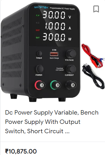
The bench power supplies may be the best option in this case. Most of the bench supplies have constant current/ voltage setup regulator, a big screen and a high power SMPS. But due to high price and availability somehow it is not possible to buy at all.
Bench power supplies:
Ac power is converted into DC through SMPS and then it is supplied to Controller circuit. Which is used to make desirable changes in the supply voltage and current. A sensitive voltmeter is connected in parallel with output for voltage measurements and ammeter in series with the one output terminal to measure current. Which is the main display of the bench power supplies. Some of them come with power measurements also.
Power = Voltage*Current
So, a small micro-controller is used to calculate the values, compute the values and to display the values.
Our setup:
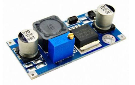
Instead of making an SMPS we can order one in cheap and then connect controller circuitry to make an own bench power supply with constant current and voltage features. We can use high power transistor for switching with linear voltage regulator. Which can give a maximum output of constant 10amperes an heavy load. Now coming to the display part, either we can use 2 multimeters, one in voltage measurement mode other in current mode. Or buy a cheap voltage-current measuring display.
Components required:
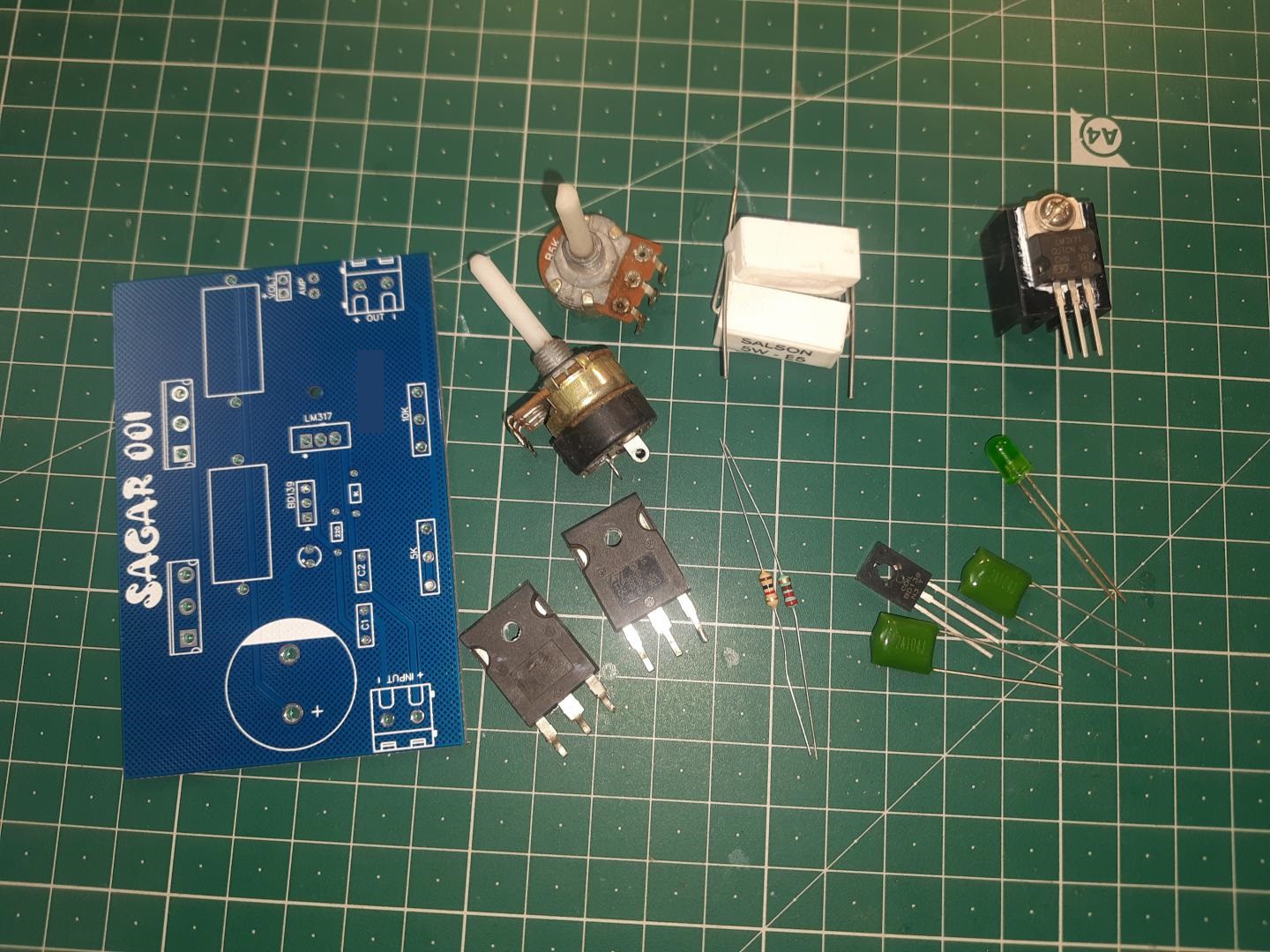
1) TIP3055 Power Transistor
2) 0.5ohms resistor 5watts
3) 10k, 4.7k potentiometer
4) LM317 Voltage regulator
5) 1k, 220R Resistors
6) BD139 transistor
6) 100nf capacitor
7) 3500uf electrolytic capacitor (50v)
8)) Custom PCB(PCBWAY)
Circuit diagram:
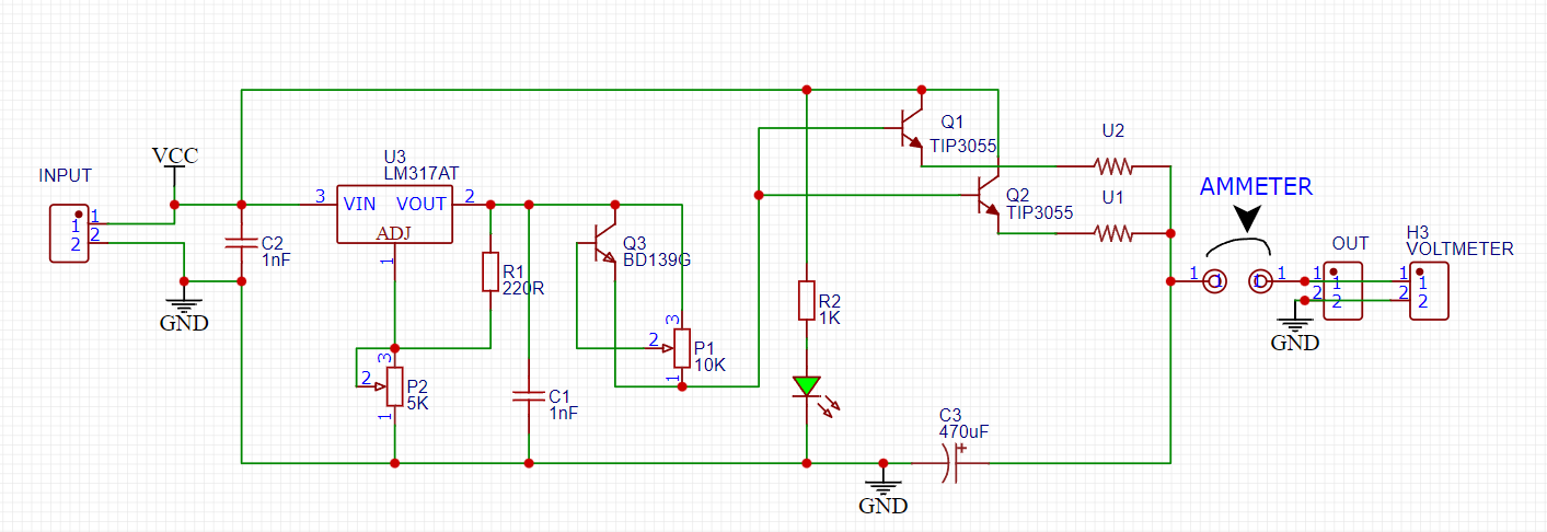
Connect all the circuitry according to the circuit diagram. 4.7k potentiometer is used for current adjustment and 10k for voltage setup. I always recommend to use this circuit only with SMPS power supply or high filtered linear power supply unit. Excessive ripple may cause problems and can change the adjusted settings with time.
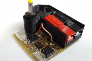
PCB Designs:
According to the circuit diagram I developed a PCB layout and if you want to use the same you can Download Gerber files from here.
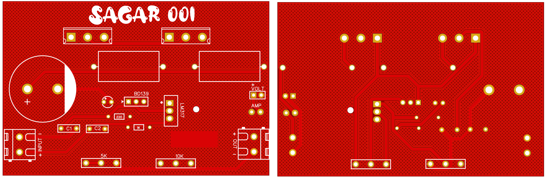
I used 1.6mm, blue colored and Hasl PCBs. These PCBs are manufactured by PCBWAY and the quality they are offering at this price range is absolutely very great. Sign-up to PCBWAY from here and get free PCB coupons. If you want to know more about PCBWAY and services then follow this article here" Why I choose PCBWAY for my projects".
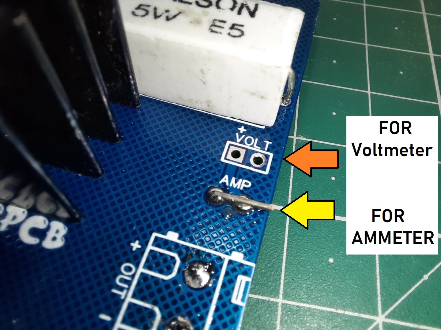
In the PCB designs I also added a voltage and current meter adding feature. As you know voltmeter can be connected the parallel with the output to display the output voltage value. In the same way current meter can be connected in series and if you don't want to use current meter for now then just short these two terminals with a piece of wire.
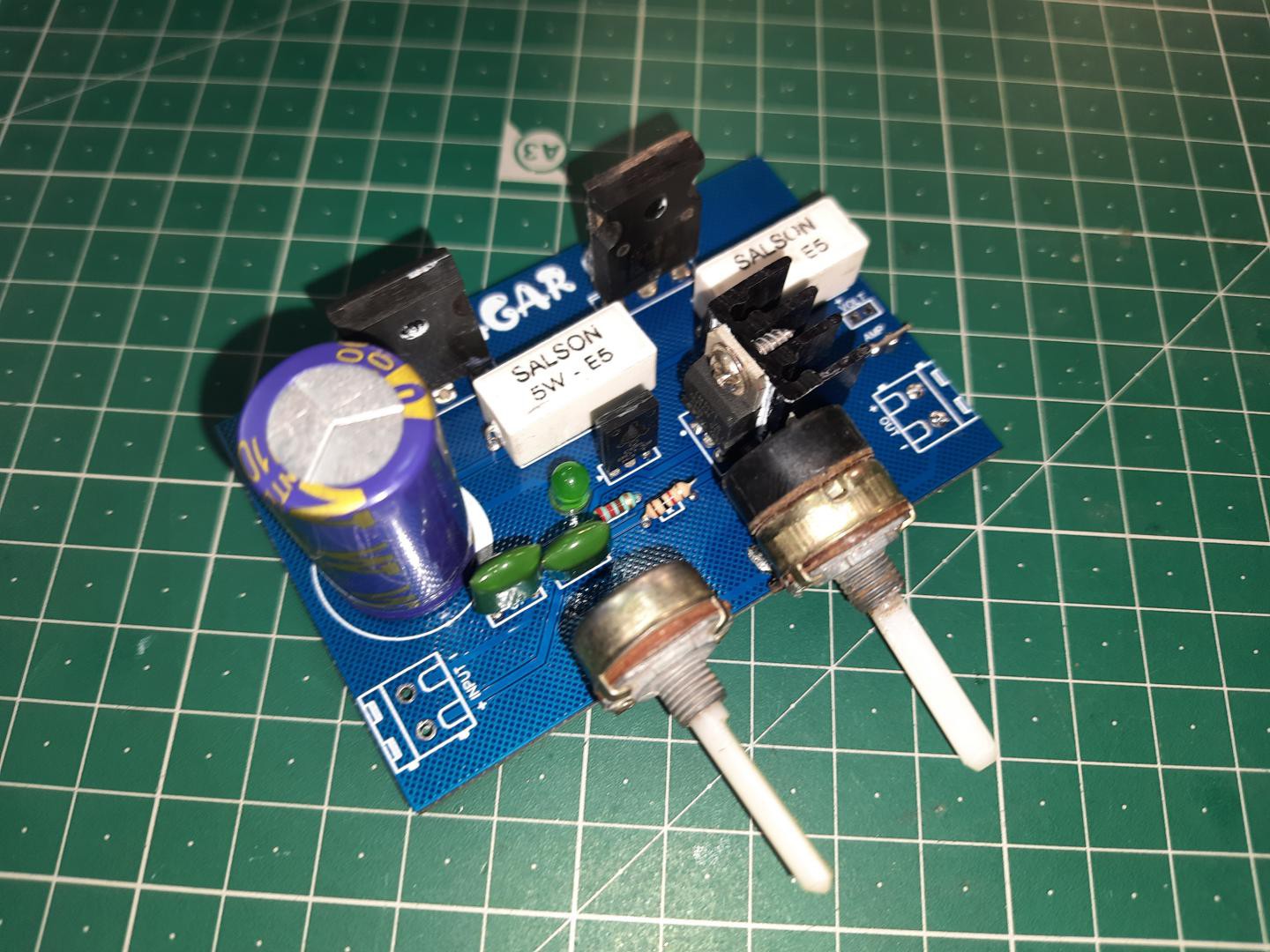
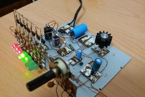
Assembly:
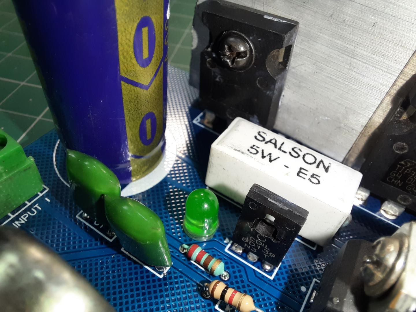
I assembled the small components Resistors/diodes first and then capacitors and other high wattage big resistors. After soldering all of these components I placed the main power transistors and soldered them on place.
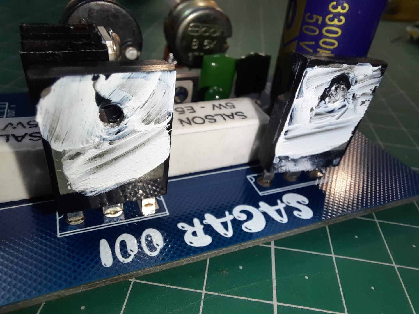
A constant current of 5-10 amperes is too much and cause heat on the transistors. So we need a big heatsink with proper compound paste and mica sheets for insulations.
Working:
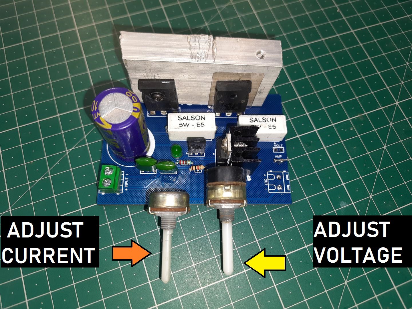
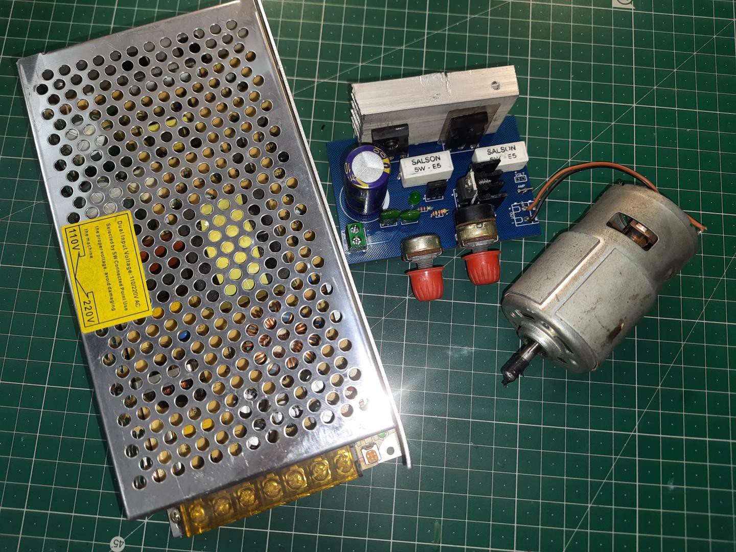
It can adjust the current from 0-10 amperes on a voltage range of 0-30 volts. If you want to test the action then a high power load may show you the proper results.
But here for the test we used this DC775 motor. And our circuit is handling this very accurately.
How to order PCB from PCBWAY:
First, Go to...
Read more »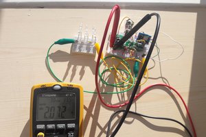
 mosaicmerc
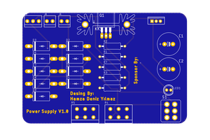
 Hamza Deniz Yılmaz