 Lithium ION
It is very easy to design a transformer less power supply, yet it is not recommended for inductive loads and microcontroller circuit. But using proper filtration circuit and voltage regulators we can use them in a good and precise manner. Usually, they are meant to supply a constant current in the circuit. Here we will know how to tune the voltage according to the needs of user, Transformer less power supply has many applications in small electronics IoT based products. Nowadays same can also be used in the LED lights as a driver unit but with a higher voltage rating.
I made the PCB of transformer less power supply for led driver. You can download the files from below and order the same PCB using Gerber from Custom PCB service. PCBWAY is the one of the leading manufacturers from CHINA deals in printed circuit board related products. You can see the different services offered by them by visiting the website.
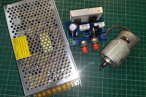
Power supply components:
In a transformer less power supply we are using a polyester film capacitor to get a step-down voltage, and a big value (250k-500k) resistor is connected in parallel to both the capacitor leads. It is a bleeder resistor whenever the power supply is not in use it will discharge the capacitor slowly to avoid any shock. It is not mandatory but if you want to use the circuit for measurement purpose then please connect this resistor. The capacitor always holds a charge equal to the peak value. This peak value can be determined by 1.414*RMS. Usual voltage in homes is 220v RMS here in ASIA.
Then next part is rectifier and filter circuit, here 4 diode combination in bridge mode is used to get the full wave output and to remove the ripples a high voltage capacitor is connected with this. This capacitor filter tries to reduce the ripple factor and increase the efficiency.
Calculating the power output:
Now here are some formulas of reactance and impedance which you can apply to your design also. First, choose the maximum output current and voltage: Say for 12v @500mA.
Calculate the impedance = Max voltage(311v) – Required voltage(12V) / (Current set) 500mA
311 volt is calculated from 1.414*220 (RMS to peak conversion)
After getting the impedance equate in the capacitive reactance equation: Xc = 0.5*Pie *frequency* C, where Xc is impedance value from here calculate the value of capacitance. Compute for the value of capacitor putting the calculated value of impedance in place of reactance. (Normal AC frequency in my region is 50Hz).
Components required:
- Polyester film 400v capacitor (non-polar)
- Electrolytic capacitor 10uf (400v)
- 1N4007 rectifier diodes
- Zener diode (suitable)
- 500k Resistor ½ watt
- Connector for AC and DC
- Custom PCB from PCBWAY
For the diode we can use simple 1A rectifier silicon diodes (IN4007) having a 0.7v drop.
Circuit diagram:
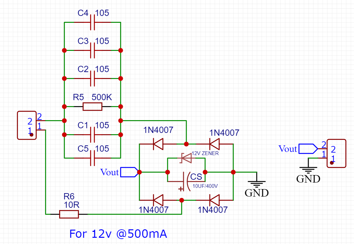
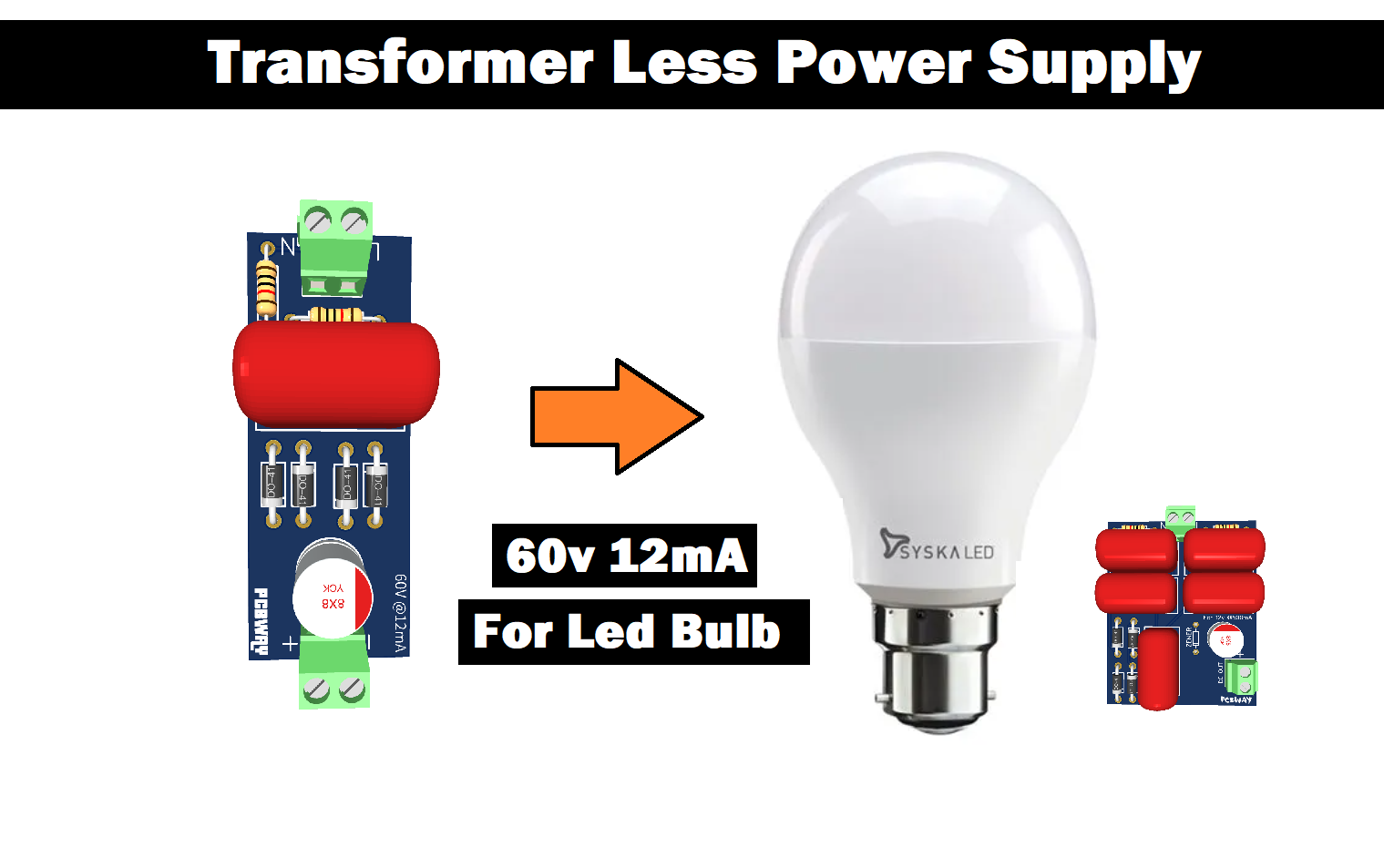
For more understanding I designed these two circuits, one for the above calculations (12v 500mA) and other one for 60v(12mA) as a 7W LED driver. You can see all the design consideration here in the circuit diagram. The problem comes in transformer less power supply when we need huge current like to drive some kind of inductive relay system.
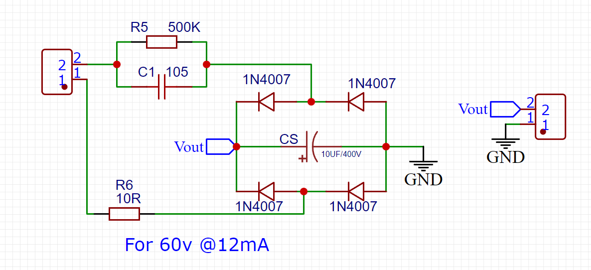
For which neither they provide current nor they are suitable for inductive type loads. For more current we can add more capacitor in parallel to the system but I always recommend to go through equations. The second big drawback is that this calculated voltage is only available when there is load connected to it. But in no load condition there are voltage peaks and they may go up to 50-60volts.
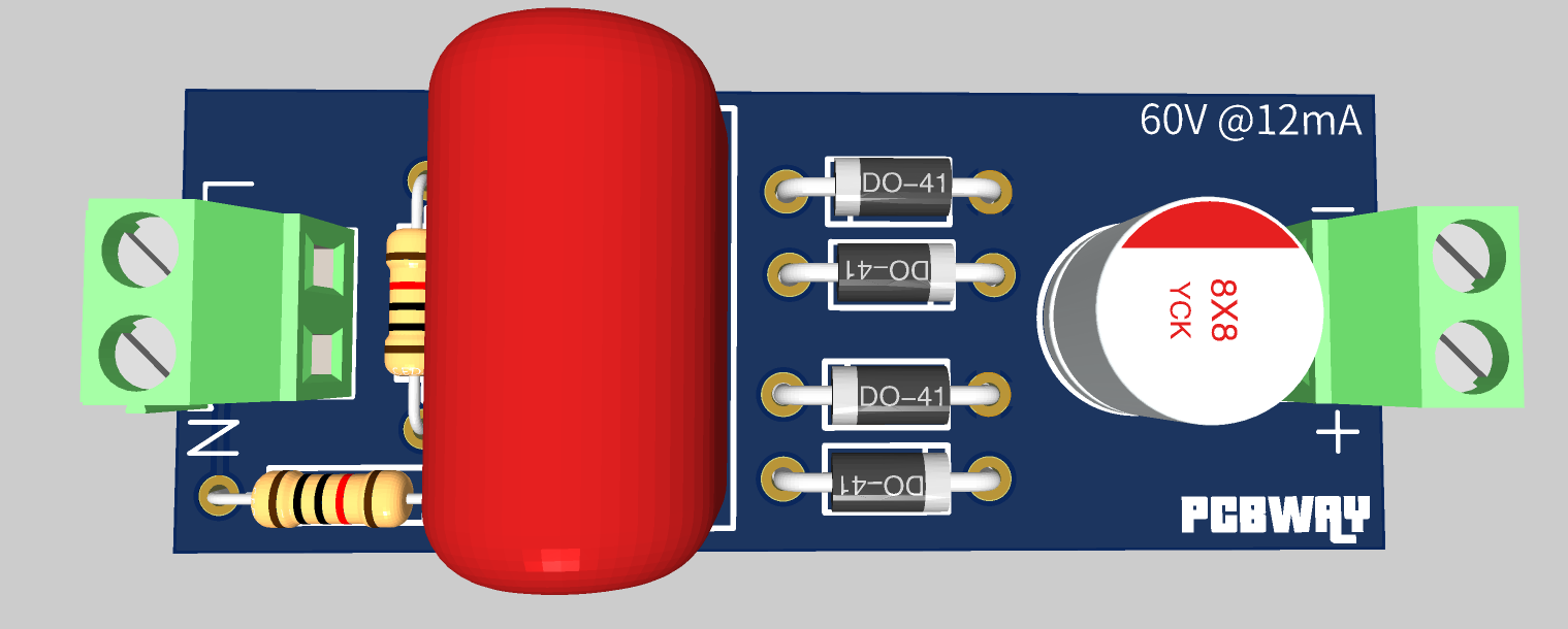
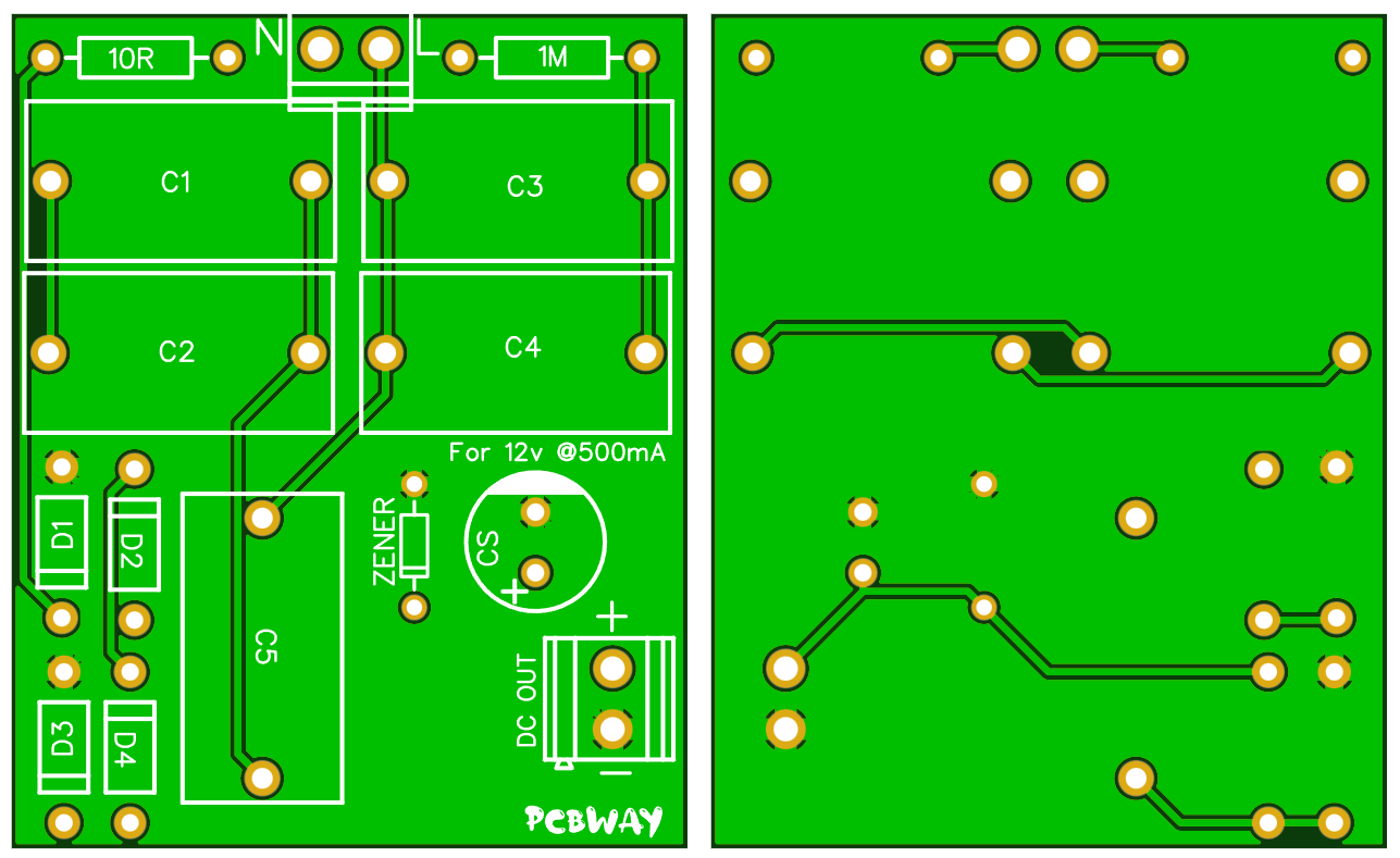
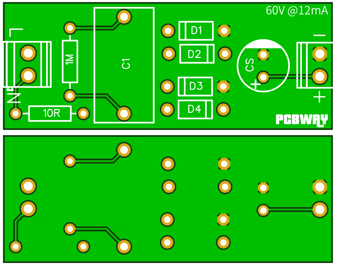
PCB Designs:
1st PCB design has 5 capacitors of 1uf, because it needs high current on output. And the 2nd one in which voltage is higher than current requirement need only one capacitor all the calculations for voltage and current are explained below.
1st design:
2nd design:
If you want to use the same design then download the Gerber files from here, you can directly use these designs...
Read more »

 Benderlabs
 adria.junyent-ferre