Friday, 18/08/2023, 10:39
Well, I need to write this somewhere before I forget.
About the controls of the mech/exoskeleton: I was thinking on using James Bruton's hall sensors idea of adding them to a rubber case, but I was also thinking on that the hall sensors would be programed to make the exoskeleton to move like it is trying to repel the hall sensors, so it will always instantaneously follow the human body and feel like it is weightless.

Well, this would only be useful in an exoskeleton, a mech with a person inside of it wouldn't have that much room for movement (depending on the design).
And I don't know how well this would work as an exoskeleton either, since the exoskeleton will always be trying to avoid the center, then it won't be supporting the user's weight.
But I won't heat my head over this simply because this is hard even for actual engineers working on exoskeletons around the world.
(I feel like I already wrote this on previous project logs)
------------------------------------------------------------------------------------------------------------------------------------------
Well, my gals and pals and goblins such as me.
Last project log I found out that micro-solenoid pump are actually viable, so in this project log I will 3D model what I think it will be necessary for the construction and working of the reversebly actuated hydraulic artificial muscles (RAHAM), starting with its pump.
So, just listing it:
- Micro Pumps 3D model (both piston and solenoid types).
- Alternating One-way Valves (AOV) 3D model.
- Molds for rubber tubes 3D model.
-----------------------------------------------------------------------------------
Also, I got an answer from a seller saying he would make an special link for me selling 180 reais (around 36 dollars) with 10kg of 1 meter long latex tubes, but when I clicked on his link, it was around 18,000 reais. Just bruh.
(but I still feel a little guilty for not buying from him)
-----------------------------------------------------------------------------------
I would need 150 solenoid pumps, but I need to do twice the number of that since each pump has 2 coils.

So, taking into consideration the proportions of the the pump we will be using, I would need a 10mm long 10mm wide shaft that would travel in total 20mm with the two coils.

I will try to buy and copy a 5kg (50 newtons) solenoid actuator and copy it, but with a few differences.
For one, I need to figure out how wide and how long the coil and core should be in order to achieve the desired actuation parameters.
Not to mention that I also need to fit two alternating one-way valves into the design and be as compact as possible.

However, I think it would be beneficial to use the following system as shown in the video bellow instead of using solenoids (for the valve):
Worst part is that I tore open a bunch of old electronics at my house and I threw alway all of their relays because I couldn't extract the iron soft core...
Now I need to find more electronic scrap...
Also, one thing I forgot to say: the idea of the micropump and the artificial muscles is that every bundle of muscle and pumps would be inside a bag full of hydraulic fluid (not that full, because these don't need that much fluid).
This way I could lubricate the sleeves/outside of the muscles and cool down the solenoid coils.
Even though I've been excited with the solenoid coils, these aren't that efficient either. A 300 watt electric motor moving a piston hydraulic pump (with the dimensions discussed on Project Log 66) would be able to achieve around 57 liters per minute, while the solenoid pump would achieve around 10 liters per minute.
... But each brushless motor pump would need to be made with laminations, permanent magnets, coils and ESC's on top of making the solid metal hydraulic pump... Which all have weight.
... While a solenoid just needs two coils to be rounded up and a center shaft, while still be lighter (supposedly).
Well, a brushless motor with 750watts of power costs around 50 brazilian bucks (10 dollars), so it would cost in total 1500 reais (300 dollars) for 30 brushless motors.
And each motor weights only 33,59 grams, totallying 1kg of extra weight and consuming only 12 horsepower (9000 watts) in total.
Of course, the efficiency of the entire system may be lower than 50%, but it would still use less than the solenoid pump (38 kilowatts).
hmmm, I guess that solenoid pumps aren't that big of a deal after all...
I would need a 10:1 gearbox because the brushless motor doesn't have enough torque for a 10mm piston pump, I could make a proper piston pump for the non-geared brushless motor, but I don't know if I would be able to make a 3.5mm diameter piston.
In either way, I will just model both (every time I say this things go downhill) because you may or may not have enough money for that (I for one don't).
-----------------------------------------------------------------------------------
Solenoid Micro pumps and Brushless motor pumps:
(If you want more details with the ins and outs of DIY electric motors, check Project Logs 58 to 61)
Maybe it will be possible to DIY tiny brushless motors weighting 30 grams... hum...
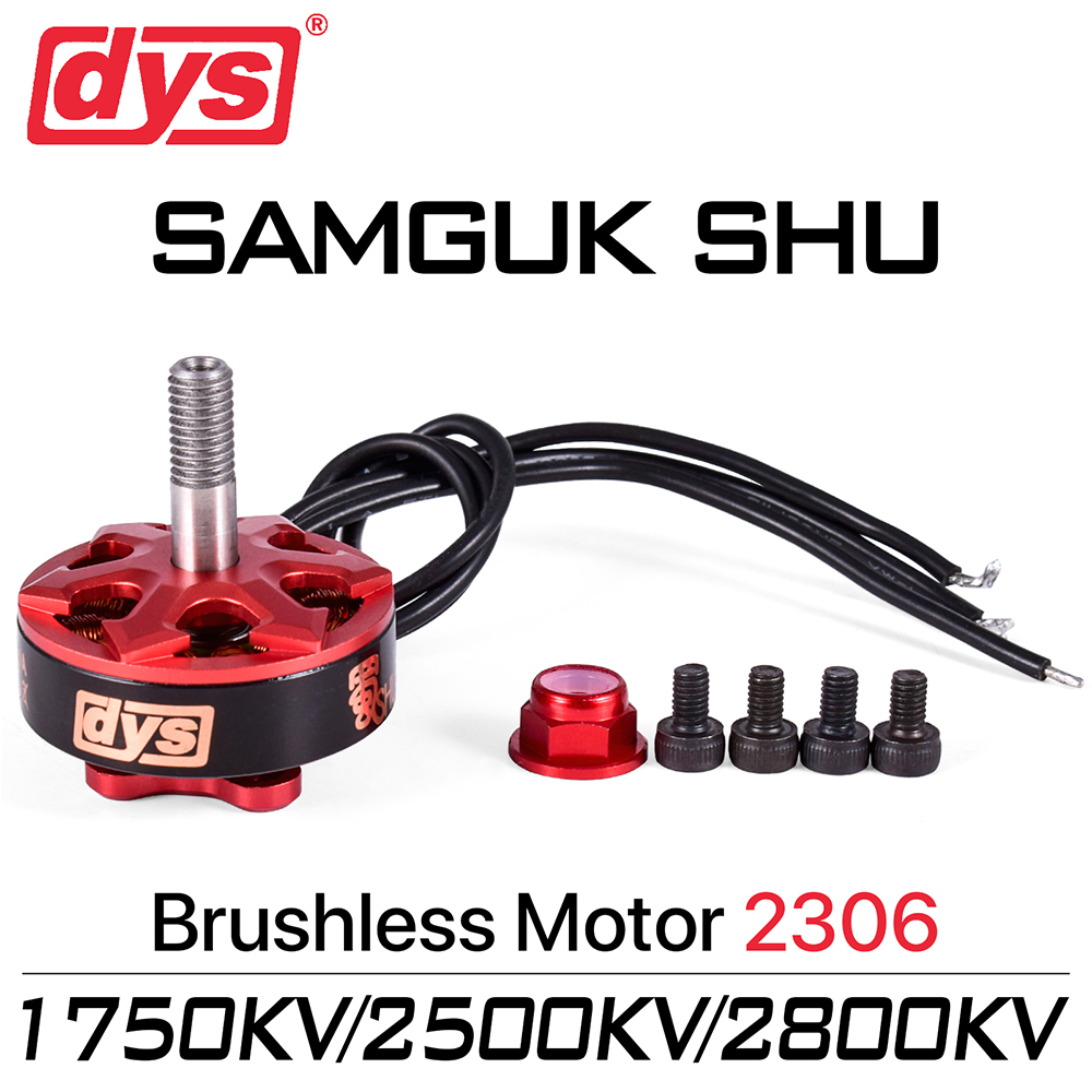
https://grabcad.com/library/dys-samguk-shu-2306-motor-1
(this one has 11 stator teeth, it should either be 9 or 12 accordingly to this sheet: https://docs.google.com/spreadsheets/d/1AZ2w6lbniuLydnSUgLaUv4zhjWA-wICHkOnHHVaU8Mg/edit#gid=352296252 )
And it seems like I was correct:
https://grabcad.com/library/dys-samguk-wei-2207-brushless-motor-1
These two models are the models that I could find for 50 reais or less, and both are 1750KV and around 700-750 watts of maximum power.
It is the brazilian Shopee, so I don't know if you will find one in your country for a similar cost:
https://shopee.com.br/product/823180042/22591630453
You buy this on your own risk, by the way, I'm just posting the link here so you can easily find a similar product to that.
The laminations need to be 0.2mm (or 0.5mm) in thickness, since the stator of the Samguk Wei (the second) has 26mm of heigth, it would need 230 laminations (a sheet of paper has 0.2mm of thickness and a 3D printer can actually achieve this precision in a single layer). With 12 perma magnets and a thicker wiring for higher output torque will exclude the need for reduction ratio.
This will give a total of 360 neodymium magnets and 3900 laminations in total, this means that every time that I melt silicon steel/iron I should have 100 molds made out of graphite and sodium silicate available.
Well, as much it is tempting to make your own brushless motors, I think it needs to be too precise for my capabilities (and a lot of time). In either way, I will at least try to 3D model.
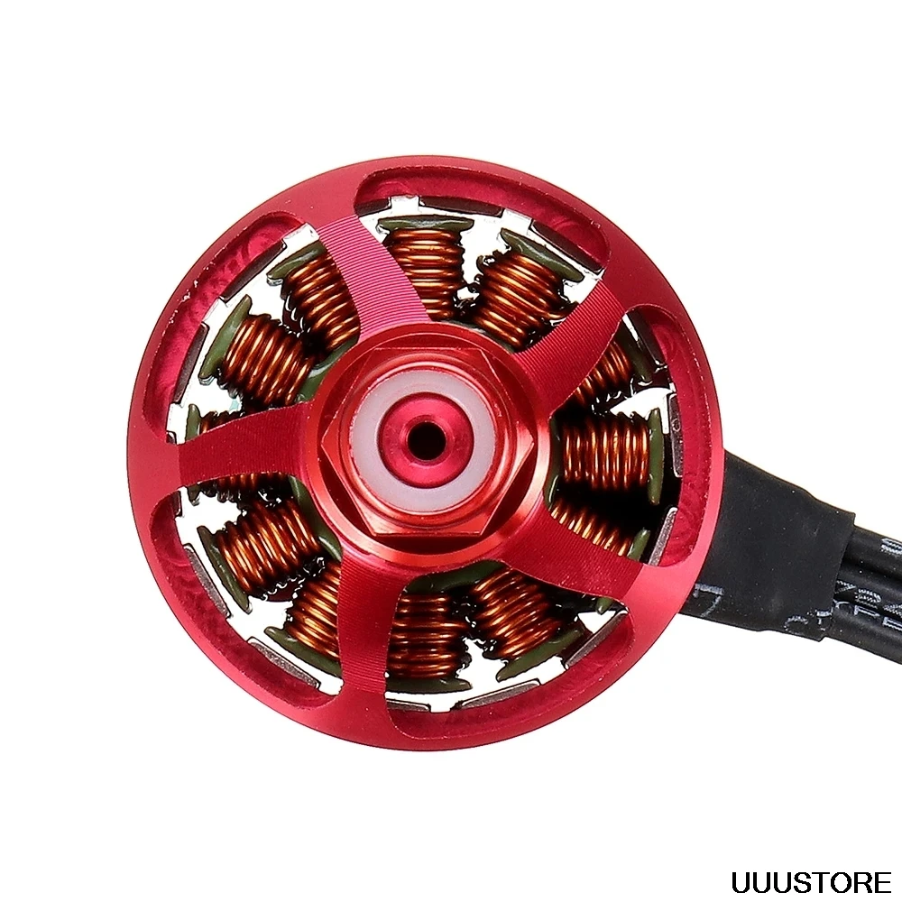
As you can see:
This motor is really tiny!
Anyway, I made the 3D model (of the stator's mold). I posted on the Files of the project here on hackaday.
What a miracle, I didn't procrastinate for 298138239 days before making any progress.

But in either way, I think this mold is quite useless, after all, it has 10mm of width. Yeah, this motor is really tiny.
You could still use the 3D models of other electric motors that I posted before, but you would need muuuuch more material compared to this little guy.
In anyway I will have to use the compressed air radial engine from Zeke Asakura as a reference. It would be nice to simply use it with the addition of the valves, but unfortunately, I do think its structure wouldn't work as a hydraulic pump because the pieces would be just too thin to be strong enough.
Plus I need to add DIY bearings into this thing because I doubt I would be able to find bearings in the sizes I need/want.

By the way, all radial engines need a "central piston" in which other pistons are attached to it, but that's for engines, not pumps. But I will just stick by the design because I'm too afraid of messing something up.
Welp, guess what? My choices are coming back to bite my arse.

The lower cylinder has 10mm of diameter and 3cm of length, the top pin has the same diameter, but 10cm of length.
The 10cm of length is the piston stroke length, and the bottom one is the actual piston.
I need to make a piston rod that somehow fits into this narrow part while not interferring with the structure.
You know what? I will just make an in line pump, I already have enough problems as it is.
 In order to make a piston rod that can allow for 100mm of stroke with such thin piston, I will need an extra long piston, which means I will have an extra long friction by design.
Also, one thing I was thinking is how to make an improvised Lathe in order to make the piston rods, I thought on putting it in a drill in the place of a drill tip and just use the sandstone in order to sand off the material until it has the ideal shape.
I thought on simply holding the drill into place with a vise or a lot of silver tape, but yeah, this does the job pretty well.
In either way, you would need a lot of attempts in order to get the right precision, so better buy a lot of 10mm thick rods (maybe made out of brass or steel, it will just be under 5 bar of pressure after all).
Also, you could mark the sandstone (or whatever you use to take off material from the piece) with the proper measurements while holding everything on the horizontal and using anything you find to put the tools in the same height.
Also, I found this cool 3d print for a "lathe adapter":
https://www.thingiverse.com/thing:2294438
There are actually a lot of useful STL's on thingiverse about CNC/lathe machines:
https://www.thingiverse.com/thing:1003137
https://www.thingiverse.com/thing:3959652
By the way, although I will make the 3D model, it doesn't mean you need the 3D model for every part.
For example, the engine block, or in this case, the "pump block". You could use the metal rods you will buy for the piston head in the mold, so once you take them off, the pistons will perfectly fit into these cylinders.
You could also just use a lever drill press to make the holes, I have one and I probably can use it also.
I choose a piston pump precisely because it is easier to make a precise hole than it is to make a gear pump with perfectly flat surfaces.
I found some really small RC gear pumps for toy hydraulic excavators, there are a crap ton of these on aliexpres for a myriad of different prices.
You wouldn't need the alternating valve, just a simple solenoid for deflating.
... But those are meant for 1 to 2 liters per minute and 100 bars of pressure, so I don't think it would be viable, you would need a conventional pump.

You could use a DIY method of expanding the mold, for example:
If you insert a silicone rubber mold in mineral spirits over night, the entire mold will expand its original size.
However, what would be the precision of such mold?
If you are going in with a coin flip in relation to the precision, then why not just 3D print the entire thing?
For my own surprise I actually made the hydraulic piston pump instead of procrastinating for weeks, but I'm not quite comfortable with the final result, it looks too nimble, too fragile and poorly-done.

With the add on of blender I could find the volume of the pump (an incomplete pump, but still), this thing in bare bones already has 3kg of weight, if there are 30 pumps, it will weight around 90kg.
Also, you don't actually need to 3D print this, you could make a frankenstein monster with linear actuators that you can buy online:
You buy this on your own risk, by the way, I'm just posting the link here so you can easily find a similar product to that.
The add on if you want to learn how to use it:
Dunno about you, but I quite like this guy's accent. I'm brazilian so I don't know which country his english is from.
In either way, if you are using the tiny, but mighty Samguk brushless motor, you would still need 10:1 reduction ratio.
I'm going to try and find 3D printable reduction boxes, or you can buy one online and make a copy, although I think gearboxes are harded to disassemble.

Found this diagram from this link on aliexpress:
https://pt.aliexpress.com/item/1005003674264682.html
You buy this on your own risk, by the way, I'm just posting the link here so you can easily find a similar product to that.
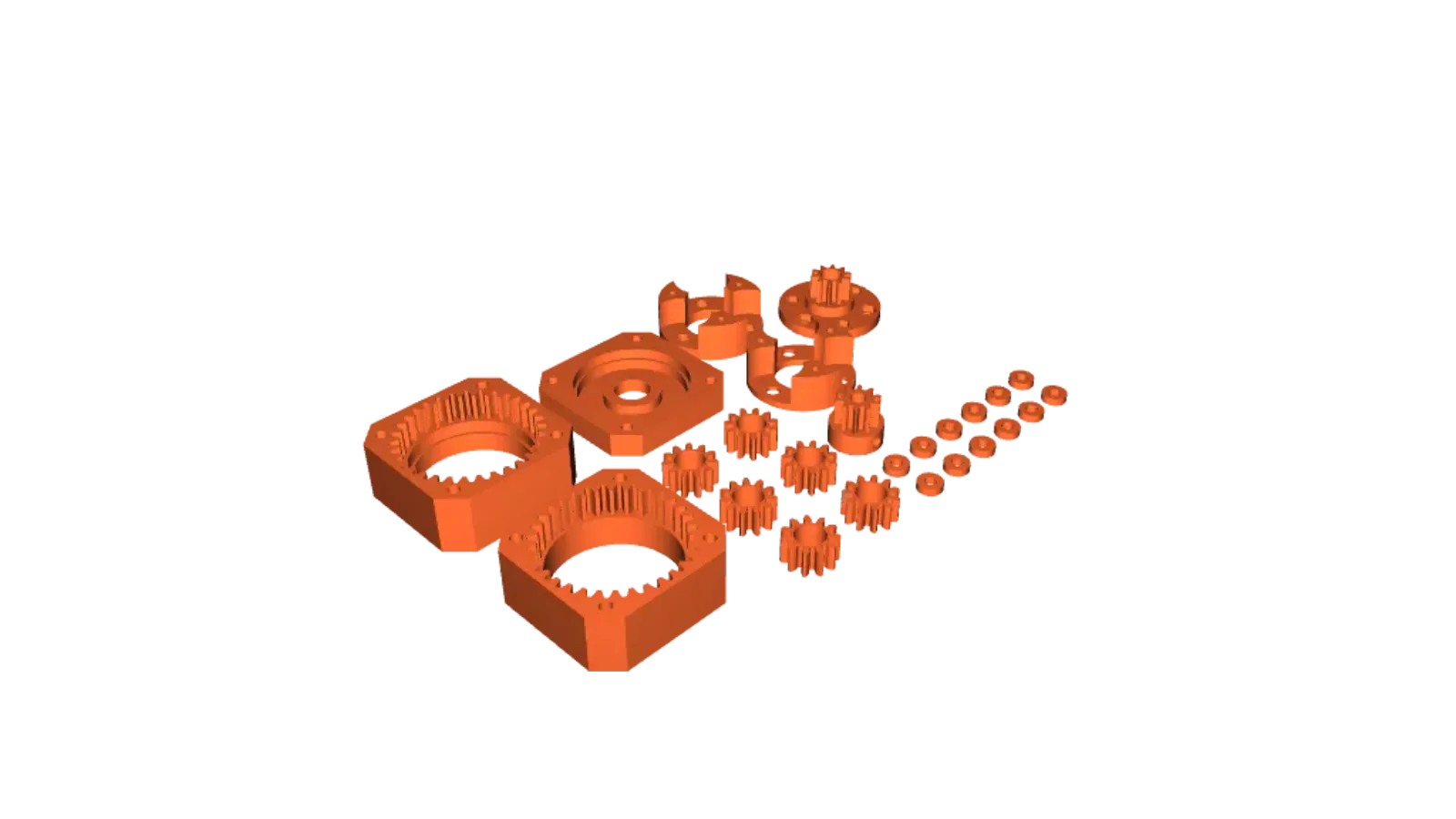
Here some 3D printed ones:
- https://www.printables.com/model/271490-nema17-2-stage-planetary-gearbox-101
![]()
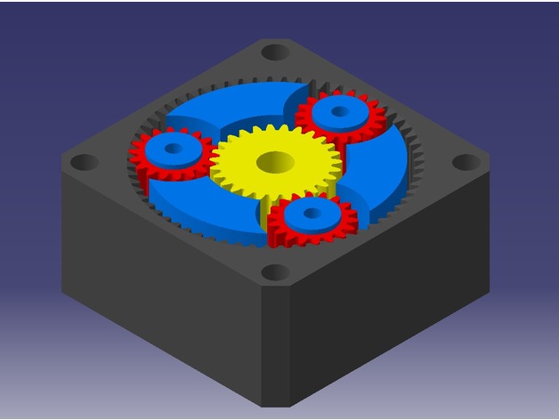
https://cults3d.com/en/3d-model/tool/worm-gearbox-i10-i15-i20
![]()
https://cults3d.com/en/3d-model/tool/stackable-planetary-gear-high-torque
![]()
https://www.thingiverse.com/thing:2106512
(It actually is a 3.33: gear ratio, but with two stacks you would get more or less 11:1 reduction)![]()
https://www.thingiverse.com/thing:1107438
(kinda sketchy to use toothpicks as shafts, but you could replace them with metal inserts)![]()


Personally, I wouldn't print/buy make a big/sturdy reduction box since the output torque is just 2 Nm for the output, nothing crazy like the robot dog from james bruton, which needs to be strong.

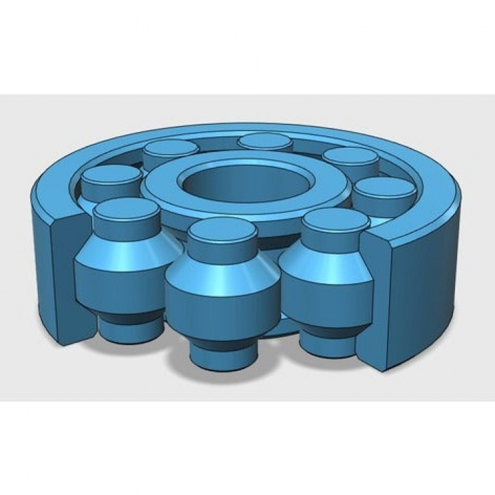
Well, I choose to work with the second 10:1 gearbox on the list above because it seems to be the simplest one. The cylinder, disks and hexagons there have the same dimensions as the screws, bearings and nuts the author suggested to use, in fact, I think I will be forced to make these from scratch using a mold because I couldn't find to buy them online (I included these in the blend archive).
I will make a little compartment to where the brushless motor will stay in.

Just now I noticed that I put the motor connected to the driven gear instead of the driver gear, I'm going to fix this tomorrow.

There.
By the way, I added a double "motorbox" to the 3D models if the torque of the brushless motor isn't enough. So you can add a second brushless motor to the other side and double the torque (and the monetary cost).
Also, now I'm worried about the resistence of the gears and screws, 2Nm to 4Nm of torque doesn't seems much, but at 5mm of distance, it is basically putting a force of 40kg to 80kg of force (accordingly to torque calculators).
Taking into consideration the amount of torque required and all that stuff, I think I will remake the hydraulic pump gearbox.
I will just put a bigger version of the current gearbox, it is still compatible with the small brushless motor as shown above.

Well, you will either need to make a costum bearing or find a bearing that closely fits the redimensioned version (although I doubt you will be able to find).
Here is a video with one that can be easily changed (I added my version to the blend archive).
Maybe this one will be easier to make, because I don't know were you will find a bearing sphere with the same dimensions:
https://www.myminifactory.com/object/3d-print-fully-3d-printable-bearing-98454
I just said this and now I found metal spheres with the exact size I mentioned, lol.
https://pt.aliexpress.com/i/32958697273.html

You buy this on your own risk, by the way, I'm just posting the link here so you can easily find a similar product to that.
If the images aren't clear enough, you can just open them on a new tab.
In either way, the screws on the left are based on the screws the author of the gearbox suggested to buy and use on the gearbox.
My 3D skills are shitty, so you are looking at custom made screws that may or may not have too big spirals.
(but I also left the cylinders with the approximate dimensions just in case you prefer to buy screws, nuts and bolts instead of 3D printing)
The screw on the right is the screw that you will need to fix the gearbox to the box where the motor will stay at (aka "motorbox"), it fits on the holes already existing on the gearbox.
The cube there is a cube that has the dimensions of the screw of the gearbox and the screw on the brushless motor, but it is a sketchy one.
I simply used a boolean substractor, so the shape of the spiral/screw inside of it is the exactly one on the brushless motor, but since the 3D model may or may not have the same type of screw, then it may be useless.

You could maybe use a rigid rubber coupling/glue to that, or later make your own using molds or 3D printing.
Also, the headless screw is meant to screw the brushless motor's base onto its box.

I think I'm making the screw spirals too thick, lol.
(the screw itself has more or lesss 3mm of thickness, so you can simply buy and use a 3M screw)
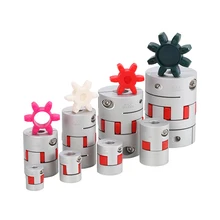
There is also this kind of coupling: https://pt.aliexpress.com/item/32862273230.html
You buy this on your own risk, by the way, I'm just posting the link here so you can easily find a similar product to that.
I mean, maybe I'm just exaggerating, no? It is just 5 bar of pressure.
Maybe if you used the 3D printed parts for molds, the performance would be better.
Some sellers post their entire product sheet, and sometimes these are actually useful (the number of sellers that post product sheets for products they aren't even selling is just...).
This one here sells this gear pump, the "HGP-3A-F30R" (the number at the end is the cubic centimeter or milliliters per revolution, the 30R has 30ml per revolution to a maximum of 2500 RPM, giving 57 liters per minute).
https://pt.aliexpress.com/item/32969548519.html
You buy this on your own risk, by the way, I'm just posting the link here so you can easily find a similar product to that.
 Well, some other sellers tell you the exactly amount of kilowatts of power you need to drive the thing accordingly to the pressure you're working with. And since you would only work with 5 bar of pressure, you would need just a few hundred watts, around 300-400 watts.
Although I'm kind afraid about the torque required, with the 10:1 reduction gear you would have almost twice as much torque you actually need for the job, but the entire system is so minuscle that I don't know if it will actually be able to do the job.
Nothing is that simple.
In either way, here is a different sizes coupling:
https://www.printables.com/model/132287-con-helical-flexible-coupler
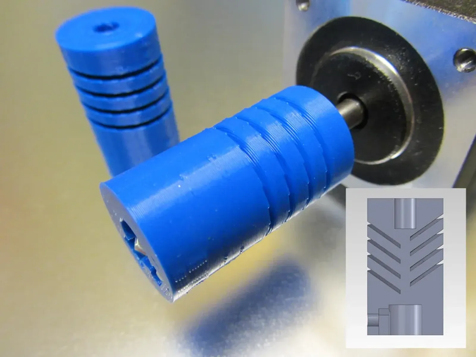
I think it may be useful to connect the gearbox and the hydraulic pump.
Or maybe this massive collection of adapters and couplings:
https://www.thingiverse.com/thing:1148295
Since the working pressure will be so low, you could also make the pumps out of other materials, such as resins and/or plastics such as HDPE or even PET, lol.
Bruh, I'm getting flashbacks from early project logs...
I could just use a belt drive with 2 to 4 belts depending on the final torque, since each 9mm belt can sustain maximum 1.4 Nm of torque, which would be easier to build, but being smart is not my strength, it seems...

You could literally buy a 10:1 synchronous belt gear drive and make copies of it quite easily....
Or just a normal pulley would be enough, I suppose...
Plus, I feel like this 3D version is a little bit sketchy, dunno if you need to make post-processing.
Now the base of the "motorbox" has 15 to 30cm of length, it will be quite a pain to fit it into an exosuit...
In any case, I still need to find a way of connecting the gearbox with the hydraulic pump. But the hydraulic pumps come in such a variety of ways that I can't think of a way of building a box that can contain both the gearbox and the hydraulic pump...
Well, I tried my luck digging images with the dimensions of the hydraulic pump and synchronous gears.
Now I need to figure out a way of making a 3d printable stand that can be adjustable for any kind of pump/brushless motor to be screwed in place


I made these, the plates are exactly the same and the screws are M6 (6mm diameter), extra information is added to the 3D objects themselves.
The motor stand isn't adjustable and I don't know how to hold the pump in place, lol.
I will try to add these features later, but I'm not going to add to this project log, it is already too long and will start deleting the text.
Also, the hole in the plate holding the synchronous belt drive is big enough to allow the pump shaft to pass through, you can simply glue or screw the plate onto the pump. I will add an alternative plate for that in specifc.
Although I'm having difficulties imagining/modelling these parts, I do think it will be possible to simply add these parts during the molding/casting process that you would do while making copies of the pump of your choice.
In any case, my apologies, but I don't feel like I'm doing a good job in the sense of 3D modelling (and in the project in general). I don't have the money nor the skills to simply buy/build these materials and simply test them out.
A more competent person wouldn't waste even 2 months 3D modelling all the necessary parts, but I'm no engineer, nor 3D modeller.
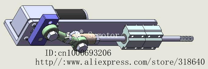
Now the solenoid Micro-pump:
Well, I didn't buy the solenoid in order to copy it, but I can copy other solenoids that already show their measurements (like I showed in the previous project log).

Well, I made a mockup of the solenoid based on the image above, and dang, it is bigger than the 750w brushless motor.

The little cylinder there has 10mm of diameter and 20mm of height, this means that it will be sitting inside a 40mm long tube were the coils will make it move.
Now I need a way of finding out how to make a cylinder keep its volume even when I'm changing its shape.
Well, that was quick.
Anyway:

You would basically need to make a coil with 20mm of height and 90mm of diameter and a hole with 12mm of diameter so you can fit the 2mm thick tube where the free piston/plunger will be moving.
In anyway, accordingly to online density and volume calculators, this coil would weight around 1.16kg. Of course, I made a solid cylinder, not a copper coil, so the weight and volume may or may not change. Plus, a modelled it a little bit bigger.
Also, the Solenoid has soft iron or steel plates around it in order to contain the magnetic field and make it stronger, just like I talked about in Project Log 61, which will also increase the weight.
I think it is not worth it, since copper wire for electronics is sold per kg or meter, and this thing needs around 1kg.
Even if the amount of copper was more or less 500 grams (like some ads show), it would still be half a package of 1kg of copper. And these normally cost 100 reais (20 dollars) per kg.
Not to mention the low efficiency and weight on the mech/exoskeleton.
------------------------------
Alternating One-way Valve (AOV):
Welp, with everything that was said above, I don't think I will need an AOV after all...
Not that I would need either tho, you just put two tubes with solenoid valves each close to another, add a limiter (like a thin metal spike) and do your thing with the programming.

------------------------------
Molds for Rubber Tubes:
Unfortunately, I'm limited in terms of size and length of the mold, because I'm limited by the size of the 3D printer. And so, I will try to make a mold that can be "added", so to speak.
Basically, first a mold that can make the tube, then, after taking off the tube, connecting the tube to the tip of the mold and filling the mold with the liquid latex/silicone rubber.
Also, I will try to make the tubes as close as possible to the ones in the 300% strain artificial muscle, simply because it is a point of reference.
If it can extend the tubes at least 60% to maximum 300% of its initial length, and the tubes have an inner diameter of 12.5 mm and a wall thickness of 1.6 mm (giving an outer diameter of 15.7mm) with 80 newtons (8kg) of force, then it is within acceptable range.
I would think that by increasing the length of the tube, it will probably increase the force applied, so the 8kg of force must come to a 32mm long tube with similar dimensions.

Well, I don't know how well this is as a mold, but you just need to insert the solid tube with 12.5mm of diameter on the center and the outer tube with 15.7mm of inner diameter and 25.1mm of outher diameter on the base mold and there you have it.
------------------------------
Elasticity enhancers:
Liquid latex aren't meant to be vulcanized (chatGPT even said it would suffer "Sulfur bloom" that will deteriorate its integrity), but one could try. You would need 1% to 5% by weight of sulfur and mix throughly, and then do the vulcanization process of microwaving and/or exposing the rubber to steam at 2 to 4 bar of pressure at 140-160ºC for 20 to 60 minutes.
Or just microwave everything for 6 minutes.
But since this method sounds sketchy to do in a DIY way, I would advise to add milk graphene to the mix and other elasticity enhancers (you know the drill: mix graphite with milk proteins in a shaker for 45 minutes and you get your bio-graphene).
"The exact percentages of additives to add to liquid latex can vary depending on factors such as the specific brand of liquid latex you're using, the desired properties of the final product, and the intended application. It's important to start with small amounts and conduct tests before making larger batches to ensure the desired results are achieved without compromising the quality of the latex.
Here are some general guidelines to consider when adding additives to liquid latex:
Ammonia: Ammonia is a powerful additive, and only a small amount is typically needed to increase elasticity. Start with around 1-2% by weight of ammonia and gradually increase the amount if necessary. Always work in a well-ventilated area and follow safety precautions when handling ammonia.
Glycerin: Glycerin is a common choice for improving flexibility. You can start with around 5-10% by weight of glycerin and adjust as needed.
Silicone Oil: Silicone oil can vary in viscosity, so start with a small amount, around 1-3% by weight, and gradually increase if more flexibility is desired. Ensure that the silicone oil is compatible with latex to avoid any adverse reactions.
Cornstarch: For adding thickness and texture, you can start with around 2-5% by weight of cornstarch. Mix it thoroughly to avoid clumping.
Acrylic Paint: If using acrylic paint for color and added strength, begin with a small amount, around 1-5% by weight, and adjust as needed. Make sure the acrylic paint is latex-compatible.
Latex Thickener: Follow the manufacturer's guidelines for the recommended percentage of latex thickener to add.
It's crucial to remember that each additive may interact differently with the liquid latex, and adding too much of an additive can potentially affect the overall performance and quality of the latex. Always conduct small-scale tests before committing to larger projects and take careful notes on the amounts used and the effects observed. If you're unsure, consider reaching out to the manufacturer of the liquid latex for specific guidance on using additives to modify their product."
"Liquid latex is a versatile material often used in special effects makeup, prosthetics, and other creative applications. If you want to enhance the elasticity of liquid latex, you can consider adding certain materials known as elastomers or elastomeric additives. These additives can help improve the stretchiness and flexibility of the latex. However, please note that experimenting with additives can have unpredictable results, and it's important to conduct small-scale tests before making larger batches.
Here are a few elastomeric additives that you can consider adding to liquid latex and their potential percentage ranges by weight. Please keep in mind that these percentages are approximate and may vary based on your specific needs, the brand of liquid latex, and the desired properties:
- Ammonium Lactate: Ammonium lactate is a chemical compound commonly used in skincare products to exfoliate and moisturize the skin. It can also enhance the flexibility of liquid latex. Start with a small percentage, around 1-2% by weight, and gradually increase if necessary.
- Glycerin: Glycerin is a humectant that can help retain moisture and improve the flexibility of liquid latex. You can try adding around 3-5% by weight of glycerin to the liquid latex.
- Dimethylpolysiloxane (Silicone Oil): Silicone oil can be added to liquid latex to increase its stretchiness. Start with a very small amount, around 0.5-1% by weight, as silicone oil can have a significant impact on the properties of the latex.
- Hydrolyzed Collagen: Hydrolyzed collagen can be used to improve the elasticity of liquid latex. Begin with around 1-2% by weight and adjust as needed.
- Polyvinyl Alcohol (PVA): Polyvinyl alcohol is another additive that can enhance the flexibility of liquid latex. Try adding around 2-4% by weight.
It's crucial to note that the addition of these additives can alter the properties of the liquid latex, and too much of an additive may result in undesirable effects such as reduced tear resistance or changes in curing time. Always perform small-scale tests before making larger batches to ensure that the resulting latex maintains the desired characteristics and quality.
Furthermore, keep in mind that liquid latex is a complex material, and the interaction between the base latex and additives can be intricate. If you are looking for a significant change in the properties of liquid latex, it might be best to explore specialized latex formulations that are designed to provide specific properties like high elasticity or stretchiness."
"Both pre-vulcanized and centrifuged liquid latex are related to natural rubber latex, but they refer to different processes and characteristics of the latex material.
- Centrifuged Liquid Latex: Centrifuged liquid latex is obtained through a mechanical process known as centrifugation. In this process, freshly harvested latex from rubber trees is spun rapidly in a centrifuge machine. Centrifugation separates the latex into different fractions based on their densities. The denser portion, which contains a higher concentration of rubber particles, is collected as centrifuged latex.
Advantages of centrifuged liquid latex:
- Higher rubber content: Centrifuged latex typically has a higher rubber content compared to other latex processing methods.
- Better quality: The separation process helps remove impurities and some non-rubber components, resulting in a purer latex.
- Suitable for high-quality products: Due to its higher purity and rubber content, centrifuged latex is often used in the production of premium products like medical gloves, balloons, and high-quality rubber products.
- Pre-Vulcanized Liquid Latex: Pre-vulcanized liquid latex, also known as creamed latex or stabilized latex, is a latex product that has been chemically treated to partially cross-link the rubber molecules. This partial cross-linking process is done before the latex is fully vulcanized (cured) into solid rubber. Pre-vulcanization improves the stability and shelf life of liquid latex and prevents it from coagulating over time.
Advantages of pre-vulcanized liquid latex:
- Shelf stability: Pre-vulcanized latex remains stable and does not coagulate as easily as untreated latex, making it suitable for storage and transportation.
- Consistency: It provides a consistent viscosity and rubber particle distribution, which is beneficial for various manufacturing processes.
- Extended working time: Pre-vulcanized latex can be stored for longer periods before being further processed into solid rubber, allowing for more flexibility in production.
In summary, the main difference between centrifuged liquid latex and pre-vulcanized liquid latex lies in their production processes and characteristics. Centrifuged latex is obtained through mechanical separation, yielding a high-rubber-content latex with fewer impurities. Pre-vulcanized latex is chemically treated to enhance stability and shelf life while maintaining a consistent composition for easier processing. Both types of latex have specific applications based on their properties and qualities."
"Enhancing the elasticity of pre-vulcanized liquid latex or centrifuged latex involves adding certain chemicals or materials that can modify the properties of the latex. It's important to note that the specific additives, their concentrations, and their effects can vary depending on the desired outcome, the type of latex, and the intended application. Always conduct small-scale trials before making large batches to ensure that the desired properties are achieved.
Here are some common enhancers that can increase the elasticity of latex, along with general percentage ranges. These percentages are provided as rough guidelines and may need to be adjusted based on your specific requirements:
- Plasticizers: Plasticizers are additives that increase the flexibility and elasticity of rubber materials. They can be added to both pre-vulcanized and centrifuged latex to improve stretchability and softness.
- Dioctyl phthalate (DOP): 5-20%
- Diisononyl phthalate (DINP): 5-20%
- Epoxidized soybean oil (ESO): 5-15%
- Other proprietary plasticizers: Follow manufacturer's recommendations
- Processing Aids: Certain processing aids can improve the processing characteristics of latex, leading to better elasticity.
- Glycerin: 1-5%
- Sorbitol: 1-5%
- Polyethylene glycol (PEG): 1-5%
- Cross-Linking Agents: Cross-linking agents can help strengthen the rubber matrix, improving elasticity and durability.
- Sulfur: 0.5-3% (for natural rubber latex)
- Zinc oxide: 2-8%
- Accelerators (e.g., thiurams, mercaptobenzothiazoles): Follow manufacturer's recommendations
- Vulcanization Accelerators: Accelerators promote the vulcanization process, which can enhance elasticity.
- Accelerators (as mentioned above): Follow manufacturer's recommendations
- Ammonia: Ammonia can alter the pH of the latex, affecting its properties.
- Ammonia solution (25%): 0.1-1%
- Fillers and Reinforcements: Incorporating fillers or reinforcements can improve the mechanical properties, including elasticity.
- Calcium carbonate: 5-20%
- Silica: 5-20%
- Carbon black: 5-15%
Please note that the actual percentages may vary based on the specific latex formulation, the desired level of elasticity, and the intended application. It's crucial to carefully follow the manufacturer's recommendations for any additives you use and perform thorough testing to achieve the desired properties. Additionally, keep in mind that certain additives might interact with each other, affecting the final properties of the latex."
------------------------------
For liquid silicone:
"Liquid Silicone Rubber (LSR) is a versatile material that offers inherent elasticity and stretchability. However, if you're looking to enhance these properties further, there are a few additives you can consider using. Keep in mind that adding too much of an additive can affect the curing process and the final properties of the LSR, so it's important to start with small amounts and perform tests.
Here are some additives that can be used to modify the properties of LSR and increase its elasticity and stretch:
Plasticizers: Plasticizers are additives that can increase the flexibility and elongation of LSR. They help reduce the hardness of the cured material. Common plasticizers include polydimethylsiloxane (PDMS) fluids. Start with a small amount, around 5-10% by weight of the total formulation, and adjust as needed.
Hydrocarbon Resins: These resins can improve the elasticity and stretchability of LSR. They are typically used in smaller amounts, around 2-5% by weight of the total formulation.
Silicone Oil: Silicone oils can be used to adjust the viscosity and flexibility of LSR. They can enhance the material's stretchiness. Start with a small amount, around 1-3% by weight, and adjust as necessary.
Thixotropic Agents: Thixotropic additives can modify the rheological properties of LSR, making it easier to handle and enhancing its stretchability. These agents are generally used in very small amounts, often less than 1% by weight.
It's important to note that the percentages mentioned above are approximate starting points and can vary based on the specific LSR formulation, the intended application, and the desired properties. Additionally, the compatibility of additives with the chosen curing system must be considered to avoid undesirable effects.
Before adding any additives to LSR, it's recommended to consult with the manufacturer of the LSR for specific guidance and compatibility information. Conducting small-scale tests is crucial to ensure that the desired results are achieved without negatively impacting the curing process or final product performance."
"Certainly! Here are examples of hydrocarbon resin and thixotropic agents that can be used with liquid silicone rubber (LSR) to modify its properties:
Hydrocarbon Resin: C5 Hydrocarbon Resin: These resins are commonly used in various applications, including adhesives and rubber compounds. An example is "Nevchem" C5 hydrocarbon resin. C9 Hydrocarbon Resin: These resins are often used to improve tack, elasticity, and other properties in rubber formulations. An example is "Eastotac" C9 hydrocarbon resin. Please note that specific product names and brands may vary based on availability and region. When selecting a hydrocarbon resin, it's important to consider its compatibility with the LSR formulation and intended application.
Thixotropic Agents: Aerosil Fumed Silica: Aerosil fumed silica is commonly used as a thixotropic agent in various materials, including silicone rubber. It helps to control viscosity and prevent settling. An example is "Aerosil 200." Cab-O-Sil Fumed Silica: Another fumed silica option that can serve as a thixotropic agent. An example is "Cab-O-Sil M5." Both Aerosil and Cab-O-Sil are well-known brands of fumed silica that can be used as thixotropic agents. Again, ensure that the chosen thixotropic agent is compatible with the LSR formulation and meets your specific requirements.
When using additives like hydrocarbon resins or thixotropic agents with liquid silicone rubber, it's crucial to follow the manufacturer's guidelines and recommendations for proper usage, including recommended percentages and mixing procedures. Conducting small-scale tests is essential to determine the optimal amount of additive for your specific application and to ensure that the desired properties are achieved without negatively affecting the curing process or final product quality."
-------------------------------------------------------------------------------------------------------------------------------
Well, now I feel like all this work was useless because I don't know how well the brushless motors will be able to accelerate and power the hydraulic pumps towards the desired fluid flow.
I would need to test it out, but in order to test it out I need money and I am moneyless.
The guy tests every single brushless motor, but you can see at 10:58 he tests every motor until they reach the maximum wattage and rpm.
I'm probably nit-picking, but it seems like the motor takes 2 to 3 seconds to reach maximum speed.
Now I wonder how fast bigger brushless motors with more or less the same wattage would act and how fast they would accelerate (I couldn't find as well explained videos as this one), but I would guess that they accelerate slower because of the increase in mass, but still, this one needs to accelerate to 30,000 rpm while others need to accelerate 1/10 of that.
I found this one, but the guy slowly powers it up.
Well, I think I will stay with this idea of multiple hydraulic pumps and brushless motors simply because bigger ones with higher wattage are more expensive than these smaller ones.
For example, the one above is a 1000 watts electric motor that costs around 200 to 300 reais (40 dollars to 60 dollars), but the small brushless motor that I showed before has 750 to 900 watts and only costs 50 reais (10 dollars).
Not to mention its increased weight.
Discussions
Become a Hackaday.io Member
Create an account to leave a comment. Already have an account? Log In.
Axial flux really does seem like the way to go for DIY brushless motors. Radial is too difficult making the complex shape stator laminations (which also waste a lot of sheet steel) and machining the iron ring for the rotor. Here's a recent design I hadn't seen before https://www.youtube.com/watch?v=SNQVJudd6BU
It certainly needs refinement, but the involute cores are brilliant because you get high iron and copper fill factor while being super easy to make, especially if you can find thinner sheet steel. You could probably cut one strip per second with a guillotine. Then stack them up with epoxy (mix in something like fine sand to prevent direct contact between the laminations) and clamp between cauls to bend them all to shape at once. The cauls could also function as a mold to cast smooth rounded ends out of epoxy to protect the winding insulation from the sharp edges of the steel strips.
There will be some work individually sanding one side of the cores flat before gluing to the back iron. Then sand it on a flat surface to level them all together. Put non-stick spacers between them that half fill the slots, and pack the remaining space full of copper wire. Use CA glue to lock it in place, and remove the spacers to leave perfectly sized gaps for the neighboring winding.
Are you sure? yes | no
I just commented that video, but thanks nevertheless xD
However, I don't think that motor has enough performance for this case in specific, it could barely start on its own.
Are you sure? yes | no
Yes, because of the poor quality construction (and seems like ESC problems too). But this style will be a lot easier to do high quality with minimal tooling than the radial outrunner. Also I think it will work better using concentrated windings and 18N20P configuration (20 iron cores in the rotor). Very tempting to build it myself, but I have so many other projects to attend to...
Are you sure? yes | no
Ah yes, the drill+sandpaper lathe... it's like an hour of work to get a rod down to perfect diameter and 5 seconds more to go too far. I did it to turn a $5 steel tube into a precision hollow shaft for a lathe I'm building. Not sure if I got it perfect enough, but if not I can use the lathe to make a better one.
Are you sure? yes | no