Sunday, 20/08/2023, 15:02
There is no way I wil be able to finish this project log in a single day or even a single week, so I will just post this here, so if someone wonders "is this project still being actively worked on?" then, they will know that I'm just bashing my head against the keyboard trying to finish this damn thing.
---------------------------------------------------------------------------------------------------------------------------------
Now the hardest part of the project: the endoskeleton/exoskeleton.
In simple terms, I will have to make an skeleton for both the Mech (thus, "endoskeleton") and for the exosuit (thus, the exoskeleton).
Although it would be tempting to simply go Ctrl+C and Ctrl+V on the human skeleton 3D models, it wouldn't be that useful for this role in specific (to be used as a mech) because the human body has a complex and numerous ligments, joints, tendons and muscles that you can't really replicate on a mech/exoskeleton very easily.
As cool as the Nanosuit or EVA bio-mech looks like, you would need to make sure more than 650 completely different types of skeletal muscles are working properly and/or aren't damaged in someway. Not to mention on how the hell you're going to realistically control and actuate all muscles in a fast and dynamic way.
Now compare it to this DIY mech/exosuit where all the muscles are exactly the same, but only change in force/pressure and quantity depending on the limb.
It orders of magnitute easier to build and/or maintain that.
But if even then you want to try it yourself, I suggest you give a look at anatomy videos:
https://www.youtube.com/@AnatomyLab/playlist
---------------------------------------------------------------------------------------------------------------------------------
Anyway, I will try to make the Endoskeleton more or less the way you would make a Stewart platform with artificial muscles (and a little like the Project Boots, the picture of this project). And maybe make the arms a little more "anatomy based" simply because they need to be more dexterous than the legs and use less force.
I mean, with a stewart platform shoulder-arm-elbow you can't even completly lift your arm (I think).
Also, if you didn't saw the full image of this project's picture, check this:
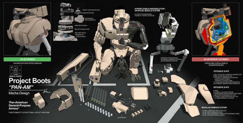
Source (I mean, I already linked the source on the project itself):
https://www.deviantart.com/ukitakumuki/art/Project-Boots-PANAM-Armour-492940388
--------------------------------
Now, the exoskeleton is another matter...
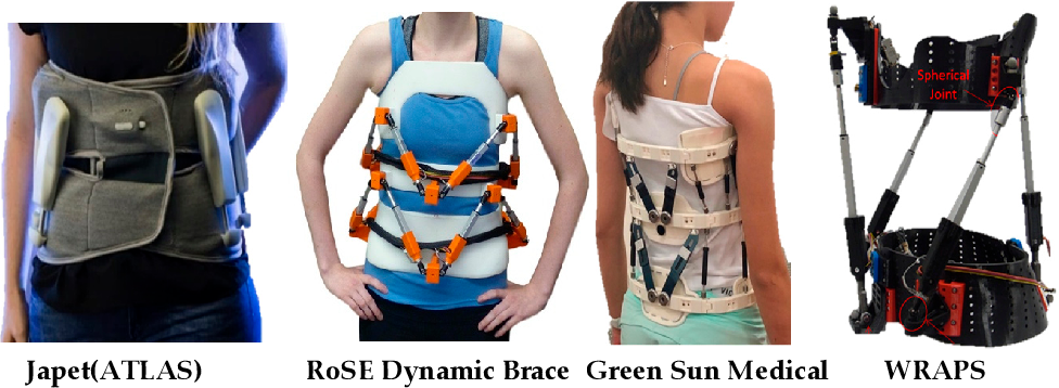
I will try to make it like the deep dive suits, where the hinges are actually rotating bearings on diagonals that allows for a full enclosed suit with a completly rigid outer shell. Then I will add an extra layer to that in order to attach the muscle strands in a similar way to the stewart platform and also do avoid the range of movement that doesn't harm the person inside of it.
You will be using artificial muscles with load capacities over 300kg to 3000kg of force (depending on how strong you want your suit to be), every care is necessary.


Ironically, a lot of these deep diving suits (up to 600 meters of depth in the ocean) are actually made out of glass/kevlar fiber composites (obviously, they are made by very qualified people), so you could try making your own versions like that.
But for the love of god, at least test the structure before using the goddamn suit.
The video bellow are simply astronaut suits that more or less work in a similar manner, not totally like what I'm suggesting tho.
Also, Adam savage is kinda cool.
https://www.youtube.com/@tested/playlists
(I tried to post the playlist for his space suit videos, but it only shows a single video instead of the complete playlist, he does some builds that actually use these angled bearing joints)
Also, he makes the space suit-like things with wood and cloth, which is readly accessible for anyone and on top of that, it may be easier to make a piece for mold casting this way instead of relying on 3D printing and/or 3D models that may need a lot of adjustments after you had all the trouble of actually 3D modelling and 3D printing everything.
As complicated as it looks (and it is in some ways), I think I kinda figured out how to make these (on blender, at least).
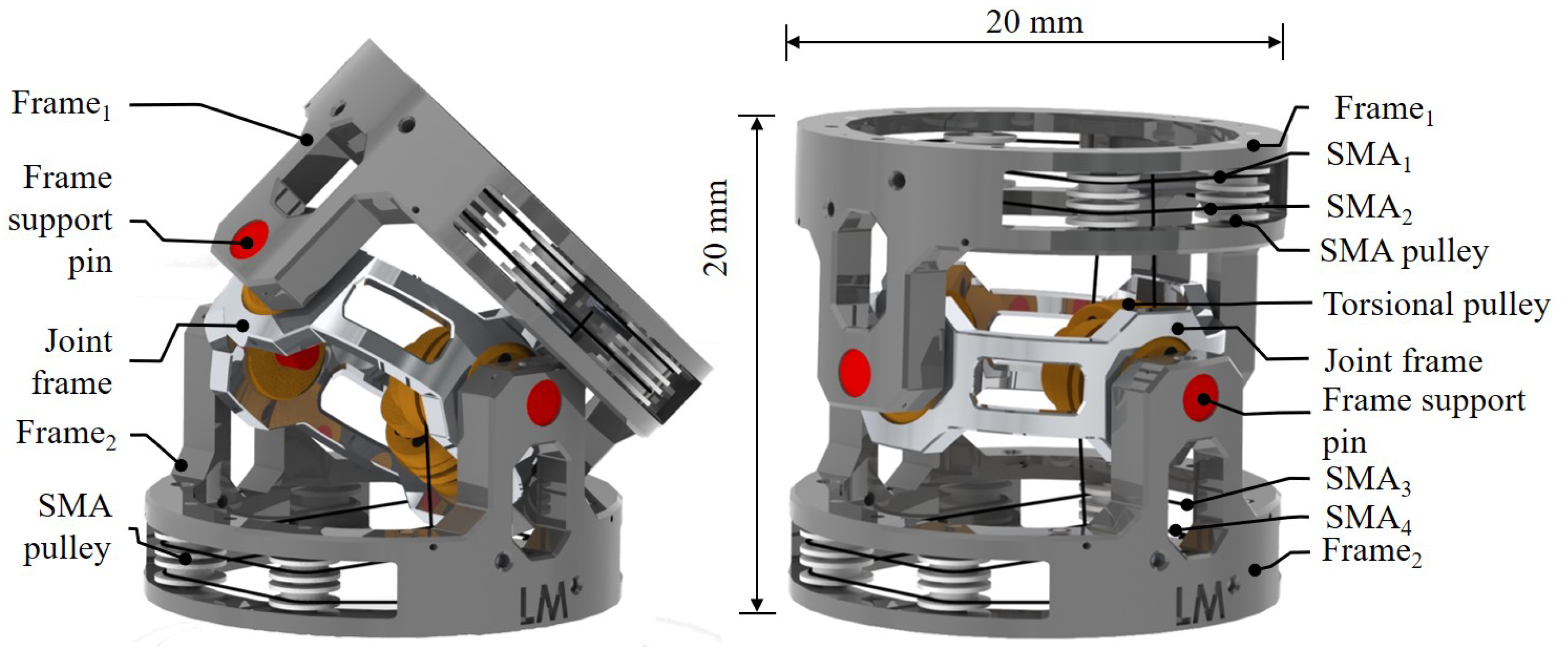
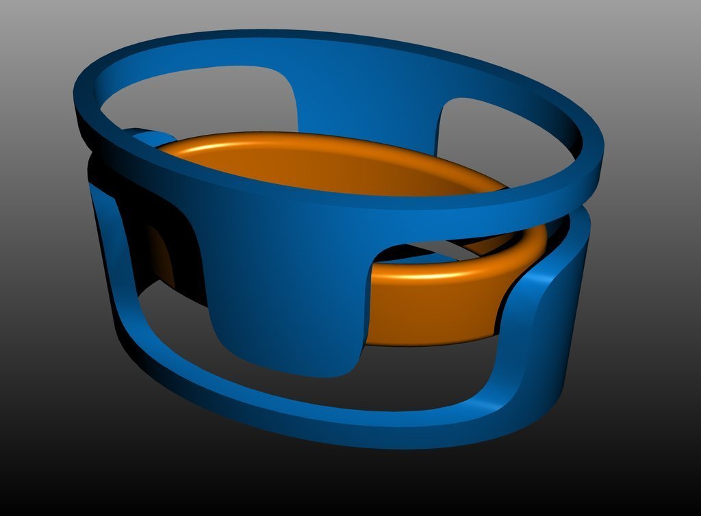
I would need to make the limbs and torso a solid tube, then add ring bearings (such as the ones bellow) and twist the rings on blender on more or less how much I would want the suit to bend over in that specific section.
If you don't know how to use Blender and want to make it for a cosplay (or for this project), I think a good way would be taking the biggest width of each limb and find a tube with more or less the diameter of this width and then cut it out on the angles you want the limb to bend.
Then the rings/bearings would more or less adjust themselves for that specific movement.
Just letting these links here because I thought the spacers used in the slew bearings was interesting and could be built with flexible materials such as teflon (but then it wouldn't be a spacer, just a holder, no?):
https://www.thingiverse.com/thing:3401856
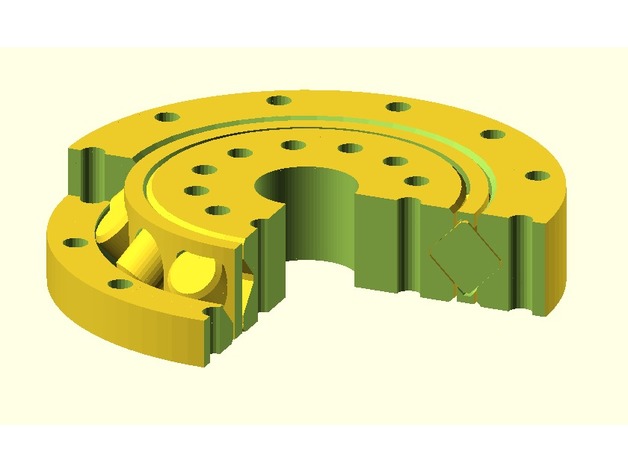 (just now I opened this bearing and it isn't complete, it is exactly like it is being shown in the image)
https://www.thingiverse.com/thing:2381833
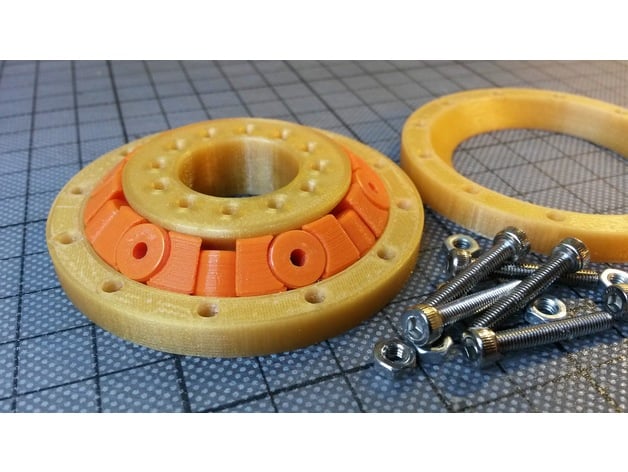
(and yes, it is a bearing made by the same guy from the video above)
----------------------------------------------------------------------------------------------------------------------------------------------
Well, I was trying to think in a way of making these angled bearing joints in a way that allows for easy maintanence, build and exchange.
I mean, yes, you can add nuts & bolts into the construction, however, you would take a while to check if every nut is properly fixed and/or taking off the nut & bolt quickly if there is an accident with the person inside of it and so on and so forth.
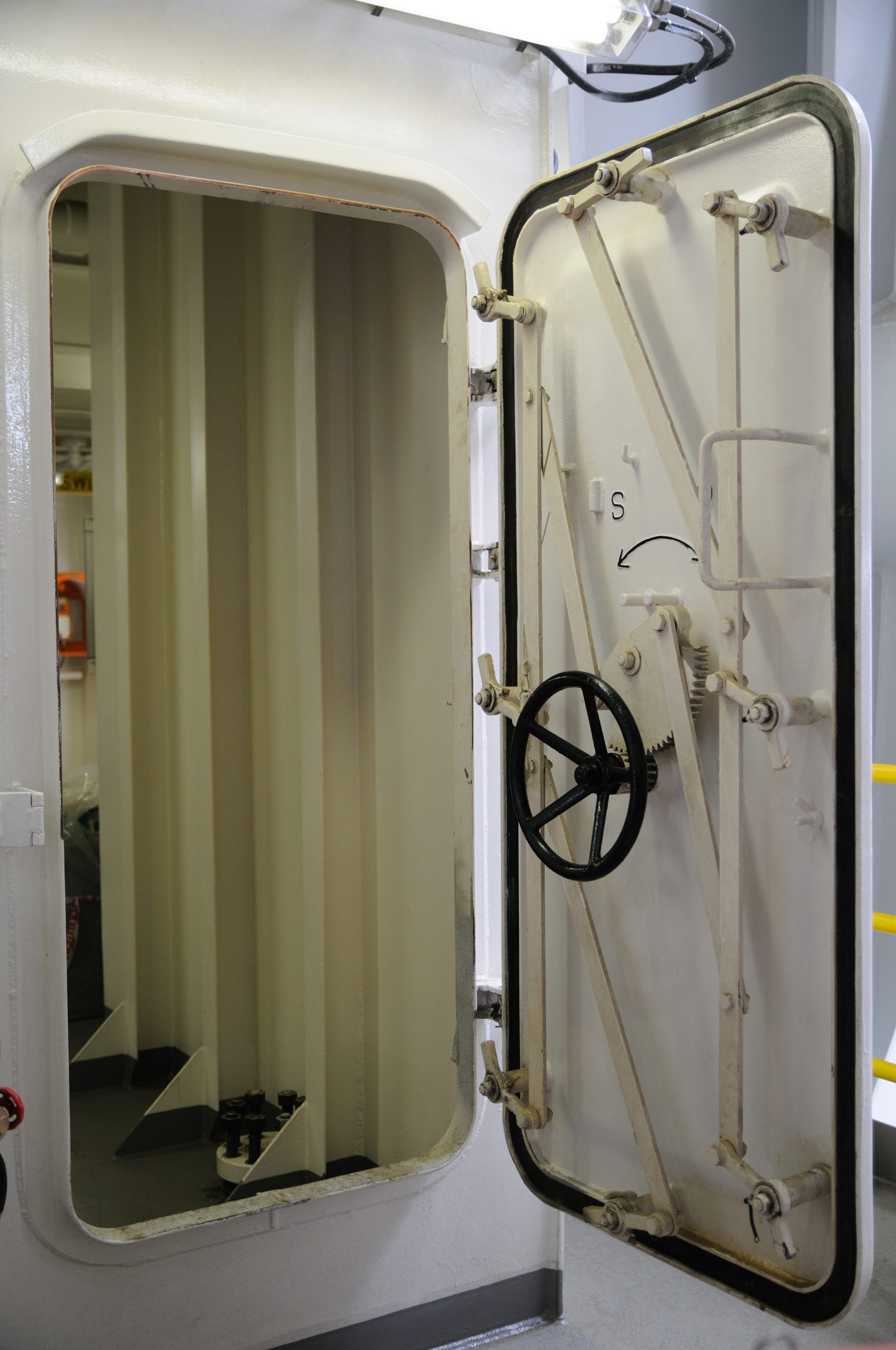
I was kinda thinking on lever-locks, kinda like the one you see in metal doors on ships. But I couldn't find any examples online.
I mean, how does one adapt this thing to an hard-suit?
The closest thing I could think of were latch lids (or jar locks, or lid clip lock jar, or whatever):
Just replace the lid and the jar neck with two rings of metal and the lock thickness dialed over 10 times (and increase its number a couple of times) and you would get a pretty solid seal without the need for thousands of nuts and bolts.
Of course, I would try to add a lot of square "teeths" in order to get the thing even more secure in place.
But I feel like I'm being over-caring about this detail, and I'm quite doubtful about its actual resilience when carrying hundreds if not thousands of kilograms of weight...
Of course I will try to add these latch lids on either the bearings themselves (which would need to be opened anyway because it is an object with 3 parts screwed together) or/and at start of each limb (like at basis of the torso, basis of the thighs etc).
Speaking of bearings...
I think I will have to make all bearings the same size in order to save time/costs at the price of making every joint a bit too large...
Actually, two types of bearings, diagonal bearigns and horizontal bearings. The diagonal ones allow for the "closing" movement of legs and arms, the horizontal ones allows for rotation on same axis.
As much as I would like, I think I will be forced to make multiple different bearings.
The torso will need extra large bearings, the legs will need medium bearings while the arms will need smaller ones.
As much as I would like to make all limbs the same, I wouldn't be able to do so because of difference in length and diameter.
Actually, the rigid space suits I posted above are actually a good example of what I'm saying and how it should be done.
Dunno if it is the angle of the camera, but the leg joints look bigger than the arm joints.
Plus, you could compensate for the difference in height with these "tubes" in the non-articulated parts.
Oh lord, I really did take a project too complex for my little brain...

----------------------------------------------------------------------------------------------------------------------------------------------
Actually I was kinda wondering if the rigid suit with the angled bearing joints were really that necessary...
I mean, in the extreme case in which you choose to make a 1 ton lifting power exoskeleton, then yes, these would be necessary, but otherwise, not so much.
I got myself thinking on a myriad of different types of exoskeletons, "encapsuling" exosuits in which the user is inside of it, like the edge of tomorrow exosuit that partially covers the user's body, "adjascent" exoskeletons that are partially copying the wearer movements like the hardiman or the exosuit from elysium/COD modern warfare, "augmenting" soft exosuits like the Nano-suit (but tuned down obviously) that simply amplifies the movement speed and/or take a little bit of the lot for the wearer and so on and so forth.
Not to mention that you could even make non-anthropomorphic exosuits that use biomimicry of animals, like that reverse joint exoskeleton from Anthem and other types of biomimicry.

The possibilities are limitless and I'm not quite sure if I should make a less powerful exoskeleton...
I mean, I think it would be for the best if I at least 3D modelled something like this, simply because I'm not good at 3D modelling and I need to force myself to be more experienced and execute my ideas more easily... It would also be a good oportunity to at least make something in real life instead of making 329328932 projects that will only work conceptually...
So, to remember:
- Make functional 3D model of a "stripped down" exoskeleton that I can actually build.
- Make a functional 3D model of a heavy duty exoskeleton with the 1 ton carrying weight (and maybe build it, if I'm not too broke in the moment).
- Make a fucntional 3D model of a Mech suit with 1 ton carrying capacity or more just like I first intended.
- Make a functional 3D model of a 5 ton or more carrying capacity Mech suit more similar to the AMP/APU suit.
If I'm going to build either of the 2, 3 and 4 options is beyond me, but I at least need to build something.
(This is me from a week in the future and I totally forgot that my short-term objective was to actually make a 100kg rated exosuit instead, so I simply procrastinated this entire time trying to think in a way of making a 1 ton rated exosuit or mech)
A positive thing about this is that I think I could use some ideas I had during other project logs in my favor.
For example, there is an attempt that I make with an exoskeleton in which it copies some robots and already existing exoskeletons, I even made an ugly-ass mockup.

This one (the middle one). I could make the joints bearings instead of electric motors and attach the artificial muscles to the skeleton (I will just call this style of joint a "bearing exoskeleton").
In the case of the 1 ton rated exosekeleton I was thinking on adding this skeleton on top of the angled bearing rigid suit I talked above for extra safety.
But the more I think about the subject, the less confident I'm being with the whole idea (for the 1 ton)...
----------------------------------------------------------------------------------------------------------------------------------------------
Also, other thing I was wondering: what name should I give to these suits?
Obviously, I thought on brazilian names, but I don't really know. I'm terrible with names.
I thought on at least naming the mech "Mapinguari" and the exoskeleton "Xangô".
If you don't know what these two names means:
Mapinguari is the name of a monster/creature of brazilian indigenous folklore that protects the forests, it is an one-eyed giant bipedal sloth with a mouth on its torso instead of having a head.
I thought on this name because Mapinguari is super big and also because the user would be piloting more or less from the mech's chest.

There are way cooler drawings of the creature on google, but mostly in a horror tone.
Now, Xangô (or "Shango") is a deity of Afro-Brazilian religion called "Candomblé", he is an ironsmith Orixá (orishas are an specific deity that are more or less the "guardians" of humans or certain aspects of humanity) of fire and thunder, wielding two axes.
He be more or less comparable with being the "hercules" or "thor" of afro-brazilian religion (he also has 3 warrior wives).

But what y'all think?
----------------------------------------------------------------------------------------------------------------------------------------------
I forgor to talk about this in previous project logs, but you could use PVA 3D printing filament to print water-soluable parts.
Why you would do such thing?
Well, if a piece of equipment that you are 3D printing for metal casting is just too complex for a refractory cement mold and/or you couldn't find a way of making high quality molds, you could use a PVA 3D printed part and/or machined part and melt the part away.
Or just use ABS and melt it with acetone and/or alcohol.
There are other types of 3D printing filaments that could be used for this task, of course.
----------------------------------------------------------------------------------------------------------------------------------------------
One thing that is kinda bugging my brain and getting me worried is the way the torso and arms would be actuated and attached.
Basically, since I will be using soft actuators (aka artificial muscles) I can't push the weight of the "artifiical rib-cage" using them.
The only option would be to use springs/struts just like in the image, but I can't use a center spring.
The struts would need to sustain more or less 100kg, and on top of that, the artificial muscles would need to surpass the force of the springs, waisting energy.
I had the idea of actually keep the "anchor" of the actuators above the "ribcage" and attach the muscles like those "impossible" chairs/tensegrity:


I hope I was clear enough with the illustration...

Here is a video on pinterest of this thing in action: https://pin.it/2NCJ1yc
(well, I don't know how well it would work with a tensegrity stewart platform)
Still, I could also make hydraulic cylinders rated fot 5 bar of pressure capable of lifting 100kg each (they would need 30 l/m and 50mm of rod diameter) and the only downside would be that it wouldn't be a compliant mechanism.
(maybe it would be necessary to make telescopic cylinders)
Funnily enough, I saw a third option in a 3D model of the Starcraft 2 CMC exoskeleton:
Well, maybe I'm seeing things, but this look like an "artificial skeleton spine", where artificial muscles would make a spine stay vertical by controlling both sides, not so dissimilar on how our actual spine muscles work to keep us stading.
However this option seems more complicated than the previous options and harder to build and/or make it work, plus, it would probably use more energy.
(the legs and shoulders are the only places on the CMC exoskeleton that have visible hydraulic cylinders, but the torso/abdomen looks way too organic to have any kind of rigid actuator, thus why I thought it uses artificial muscles).
... In hindsight, maybe it wouldn't be that bad to try and make an artificial muscle spine or something like that, because it is a type of continuum/tentacle robot.
Meaning that I could use it for other parts of the body in a somewhat safe manner.
But again, the problem is myself.
I'm at my limit in the matter of the structure of robotics.
I'm choosing all these not-so-good options for exoskeleton or endoskeleton because these are the simplest ones to build and manipulate.
I don't know how well I would be able to control the spine without a feedback loop (aka putting sensors on the robotic spine in order to its program correct its position and trajectory), unlike the rest of the body that would be using a simpler method.
I'm not very confident on my (learning) skills on the subject in order to make a good continuum robot/artificial spine, how I would avoid it simply buckling on its own weight and so on?
I explain this below, but maybe it could be possible doing this spine by using "linear limiters" (like a strut, but empty) and make a series of stewart-platforms using these and add the artificial muscles over it.

(this is a stewart platform tentacle robot that James Bruton made)
This method would be better?
Or I could just make something like this for the torso, that is way simpler and easier:
This is a hollow universal joint.
Side note: I saw this exoskeleton for neck, probably for rehabilitation, but interesting nevertheless:
Source: https://uwrl.mech.utah.edu/2021/07/02/past-present-future-neck-exo/
Well, like I said, another issue would be the shoulders, the artificial muscles can only pull, and that pulling action would mean that I would need a skeleton to avoid the muscle from simply crushing the arm/shoulder instead of making a non-deseriable action.
However, I don't know how to fit an artificial skeleton joint that would avoid that.
Meaning that I would need to make a conventional stewart platform that also uses too much energy for redundant actions.
I mean, even if I used a similar approach as the thighs/legs, I would still just make an exosuit that pulls the joints towards the body. This wouldn't be a issue for an endoskeleton mech, but it is for an exoskeleton.

Source: https://journals.sagepub.com/doi/10.1177/0278364917706743
Well, another option would be to make an "adjascent" stewart platform with an endoskeleton that follows the wearer's movement instead of putting the wearer inside of the stewart platform.
I will try to illustrate it:

The stewart platform using artificial muscles on the drawing is simply levitating in the illustration for the sake of clarity, but the idea would be more or less something like this.
That is what I meant by "wearing exoskeleton" and "adjascent exoskeleton", a subtle difference, but a difference nevertheless.
In any manner, I believe the second option would be very limiting, unlike the first option.
...Which is a little bit annoying for me. I kinda wanted to make it a fully McKibben actuated exoskeleton...
Maybe I'm overthinking it and the bearing exoskeleton for the shoulders will suffice... If I were to attach the muscles on the shoulders only instead of connecting the shoulder to the arm (an illustration below shows what I mean).
... But I don't think it would be the best option, the conventional stewart platform will have the same joints for every actuator, while the exoskeleton bearings will have a lot of different "skeleton" parts to put together...
---------------------------------------------
Also, you can make hydraulic cylinders with pvc pipes or other materials such as aluminium tubes and so on.
Although some of the authors say their hydraulic cylinders can reach forces up to 150kg, I'm very doubtfull about their resilience on the long run.
But I mean, there will be 100kg distributed between all of them, so each individual actuator would experience a force of 16kg.
This one is telescopic, but it seems a little bit fragile for my taste, dunno if it would be possible to make the first idea I had for this, with telescopic stewart platforms that replaces the shoulder and the biceps (if you can make the telescopic actuator double acting with pulling and pushing, which is not the case).

(the black square there was just the cursor selecting the colour and ended up on the print, lol)
(which makes me wonder why I didn't simply choose to work with DIY plastic hydraulic cylinders from the start instead of going though all this work to make this artificial muscle thingie...)

... Or maybe not.
A single hydraulic cylinder actuator outputs 10kg of force by having 1.6cm of rod diameter, 5 bar of pressure and around 6 liters per minute of fluid flow.
A single filament muscle would be able to output 10kg with 5 bar of pressure and 1.8 to 2 liters per minute of fluid flow.
So it would consume almost 3 times less energy to actuate, unlike the hydraulic cylinder.
... Well, maybe my calculation is at fault, or maybe the difference is too insignificant for having the trouble of making artificial muscles with limited actuation instead of cylinders with up to 90% of contraction...
Maybe not, I think I misscalculated.
The muslces shortens in length by 20% and increases diameter by 40%, so the difference would be 0.021 liters, which would be 6.3 liters per minute of fluid flow.
So it uses the same amount of fluid flow.
hum...
---------------------------------------------
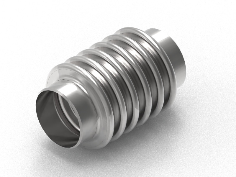
In either way, another idea I had was using cascading/bellow pieces for the shoulder (in the case for the 100kg rated exosuit, the 1 ton wouldn't be so forgiving), not so dissimilar from the astronaut suit from Adam Savage.

Something akin to that, but more rigid.
Source: https://www.printables.com/model/22487-flexible-segmented-hose-100mm
More like this, but with a larger diameter, fewer pieces and maybe with smaller ones closer ones closer to the shoulder and larger ones closer to the chest.
This piece would be under constant tension from the shoulder's muscles.
... Or I could just stop procrastinating and finally finish the bearing exoskeleton and use that instead...
You know what?
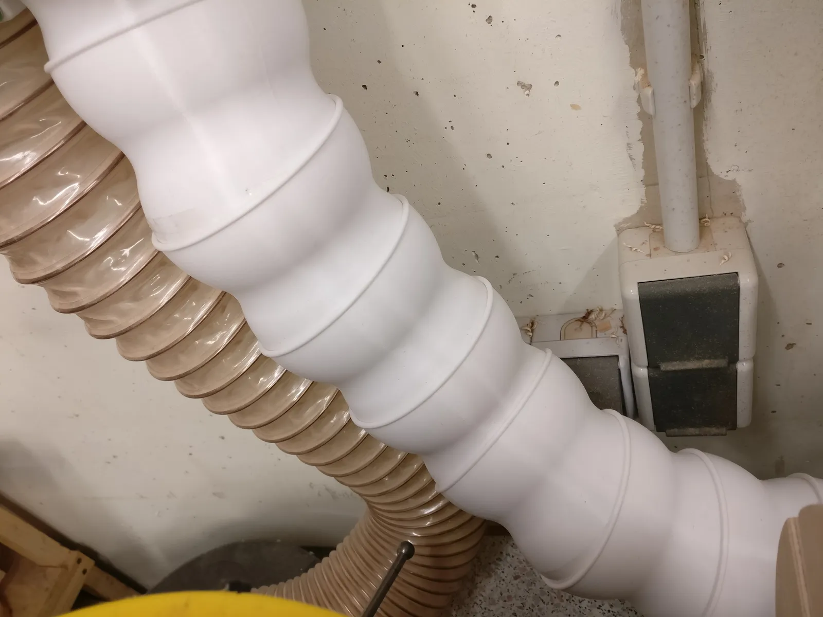
I was thinking here... I think that the best way of making a cheap exoskeleton would be making an structure that works like a corrugated/bellow pipe.
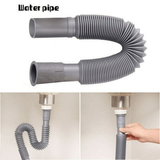
Imagine this but instead of being placed under the sink, it is a big corrugated pipe made out of plastic or metal and the structure would be under constant tension towards its base (which would be compression).
This way it would be "easy" to build it and relatively cheaper.
... The problem is that I don't know how to do that. I need to think in a way of making a corrugated/bellow geometry that can be printed and turned into a mold. ... But how does one make a corrugated pipe the size of a fricking torso?
I could make it like ring scales... No, I'm just repeating ideas...
But again: I don't know how well it would peform.
Everything works in hyphotesis, not in reallity.
... Now I have some idea why developing stuff is had as heck, you always get into a tree of possibilities.
---------------------------------------------
I forgot to say this, but I think I got an idea for the shoulders, which would simply use "linear limiters", basically, empty pistons/struts, so the muscles would always be under tension, but I could make other movements.
I think I got this idea before but I forgor to writte it down...
Although I don't know how well this would be useful for the torso.
Yes, I suggested the suspending option, but after thinking about it for a while, I don't know how well it would peform...
---------------------------------------------
I was thinking in a way of suspending the user/pilot inside the exoskeleton without activating it.
Basically, the exoskeleton moves with the users movement (duh), however, how does one control the exoskeleton with its body movement and has its weight supported by the exosuit at same time without activating it?
If you simply release your own weight, the exosuit will activate with the force generated by your body's weight.
I was thinking in a very simple, but sketchy solution.
Basically, the idea would be to basically make a "solid underpants" with a bike seat.
The user would be suspended by the seat while the suit is locked, then the position would be "zeroed" by interpreting this position as the initial position and initial load on the mech.
Then you would (supposedly) be able to control the exoskeleton with your body movement without much resistance.
I think I explained it well enough, but here is a picture of something similar to what I'm talking:

This is a exoskeleton figure called "Machinen Krieger", but you can see more or less what I intend on doing.
Also, shout out for the creators of this thing for going so far as to actually care on how to make the exoskeleton work, even though I don't like how to the shoulder mechanism is a simple 3DOF thingie.
----------------------------------------------------------------------------------------------------------------------------------------------
10 days and I'm still procrastinating in this part... Ugh...

I want to make this, I want to finish this, but I can't.
I just look at a blank archive for hours and my body refuses to do it. :|
----------------------------------------------------------------------------------------------------------------------------------------------
I can't believe it took me a month just to do this...

Of course, this is for the 1 ton rated exoskeleton, the 100kg rated is "easier" to DIY and can be made with the thingiverse slew bearings.
But I'm gonna do it first because it is simpler.
It took me 2 hours, but here it is the Slew Bearing I've made on blender based on the previous ones at the start of this project log.
... And just now I noticed that I messed up the dimensions of the rollers... I mean, I think I did...

The slew bearing has 3 parts, where normally the inner ring has 2 parts held together by screws, this one actually have the two parts on the outer ring.
It has 12 holes with 9mm diameter on the inner ring and the outer ring that are meant for screwing to something and 12 extra holes on the outer ring for holding it together.
Also, I forgot to add the hexagon hole on the thing, but I don't think it will be that much bigger of a deal since this is meant to be made out of reinforced HDPE.
I will try to make a 3D model of the exoskeleton bearing for the 100kg rated later, it will take a while also.
Well, it is "later" and I'm not in a nice mood.
In few words, I feel like all my efforts are meaningless.
But in any manner, I will try (again) to make the exoskeleton structure as the 3D model and use that finite element simulation in order to see how it would fare with the loads applied to the structure.
Without an actual test in real life or in a simulation, all of these 3D models are useless.
This also means that I need to learn to work with other programs like CAD and Fusion360 in order to properly 3D model and simulate these things.
I feel like my efforts on 3D modelling through blender aren't going to pay off... But I don't know enough to actually be certain of such thing, I'm probably a noob also in blender and so on.
In any manner, I will be studying more... And more...
Not to mention that it is quite the pain in the ass (to say the least) to literally spend days or even weeks doing something just to understand that all I have done was meaningless and useless for my application.
:|
----------------------------------------------------------------------------------------------------------------------------------------------
Off-topic:
Well, there are liquids called "electrorheological fluids" that are basically liquids that thicken when a current passes through them, just like a magnetorheological fluid thickens when a magnetic field is applied to it.
However, these electrorheological fluids need high voltage low amperage currents in order to "activate" its properties, and piezoelectric devices produce high voltage low amperage during impacts...
So I was wondering if it would be possible to mix the two, either by breaking piezoelectric devices to fine dust and mixing with the electrorheological fluid or dipping the entire piezoelectric device on the fluid.
I wonder if it would work or not...
By the way, I think it could be relevant for a impact absorbption material, just like non-newtonian fluids/sheer thickening fluids
"Electrorheological (ER) fluids are typically composed of suspensions of solid particles in a liquid carrier, where the behavior of the fluid's viscosity can be controlled by applying an electric field. The choice of materials used in ER fluids can significantly affect their performance and response to electric fields. The following are some common materials found in electrorheological fluids:
- Solid Particles: The particles suspended in the fluid are usually polarizable materials, meaning their electrical properties can be affected by an electric field. Common solid particle materials include:
- Silica: Silica particles are commonly used due to their polarizability and availability in various sizes. They are often surface-treated to enhance their dispersion and stability in the fluid.
- Polystyrene: Polystyrene microspheres can be used as the solid phase in ER fluids.
- Metal Oxides: Materials like titanium dioxide (TiO2) or barium titanate (BaTiO3) can be used for their piezoelectric properties, which contribute to the ER effect.
- Clays: Certain types of clay minerals can also be used as solid particles in ER fluids.
- Liquid Carrier: The liquid component of ER fluids acts as a carrier for the solid particles and helps to maintain their suspension. Common liquid carriers include:
- Mineral Oil: Mineral oil is a commonly used carrier fluid due to its low viscosity and stability.
- Silicone Oil: Silicone oils can also be used as carrier fluids.
- Hydrocarbon-based Liquids: Various hydrocarbon-based liquids can serve as the carrier fluid for ER suspensions.
- Additives and Stabilizers: Various additives can be included in ER fluids to improve their stability, dispersion, and performance. These may include surfactants, stabilizers, and rheology modifiers.
- Electrodes: ER fluid applications often require the use of electrodes to apply the electric field. These electrodes can be made of conductive materials like metals or conductive polymers.
The specific combination of these materials, their particle size distribution, surface modifications, and the formulation process play a crucial role in determining the behavior and responsiveness of the ER fluid to electric fields. Researchers and engineers working with ER fluids often tailor these materials to achieve the desired rheological properties and performance characteristics for their specific applications."
Discussions
Become a Hackaday.io Member
Create an account to leave a comment. Already have an account? Log In.
This just reminded me of a cool project with similar bearings on the wrists https://hackaday.io/project/182971-3x0-3d-printable-exoskeleton-concept
It's an un-powered exoskeleton, but still good inspiration for design. He hasn't updated the project page in over a year, but there are some newer pictures on his instagram.
Are you sure? yes | no
That is a really nice project, thanks for the suggestion :)
Are you sure? yes | no