 hamster
Introduction
Do you remember Christmas morning, opening up your presents, and finding a Radio Shack 100-in-One kit there? Maybe I'm showing my age, but for me that was one of the best gifts.
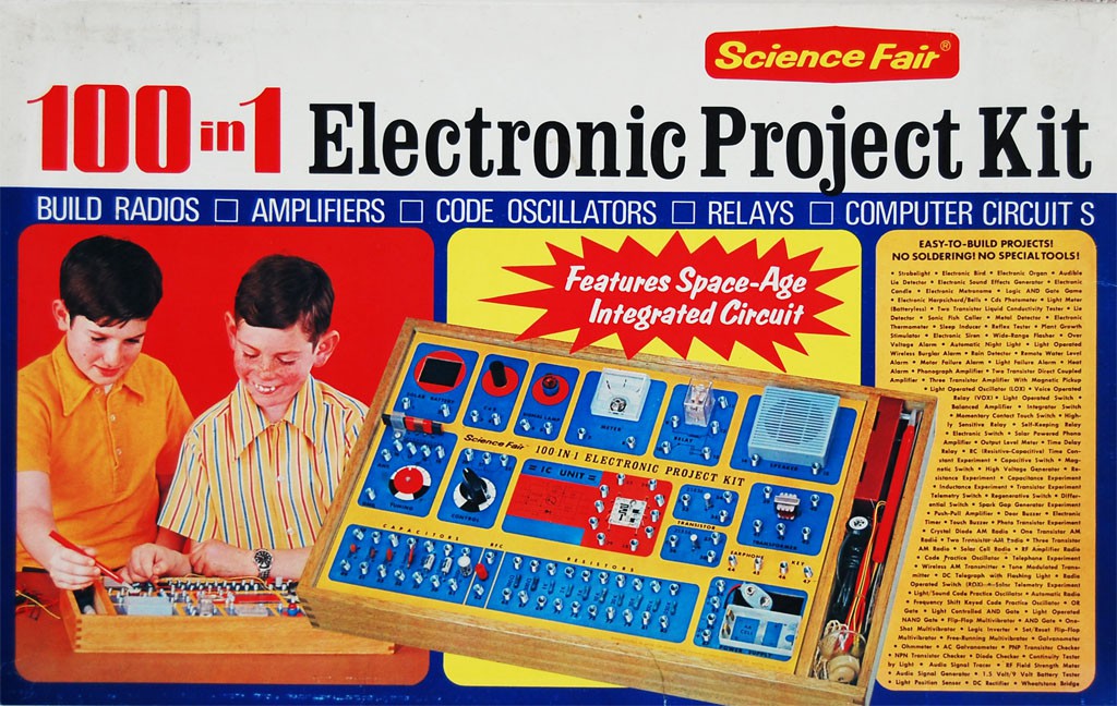
When designing this badge, I really wanted to bring that feeling of discovery back. What I really wanted was spring terminals too, but I didn't manage to make that happen...
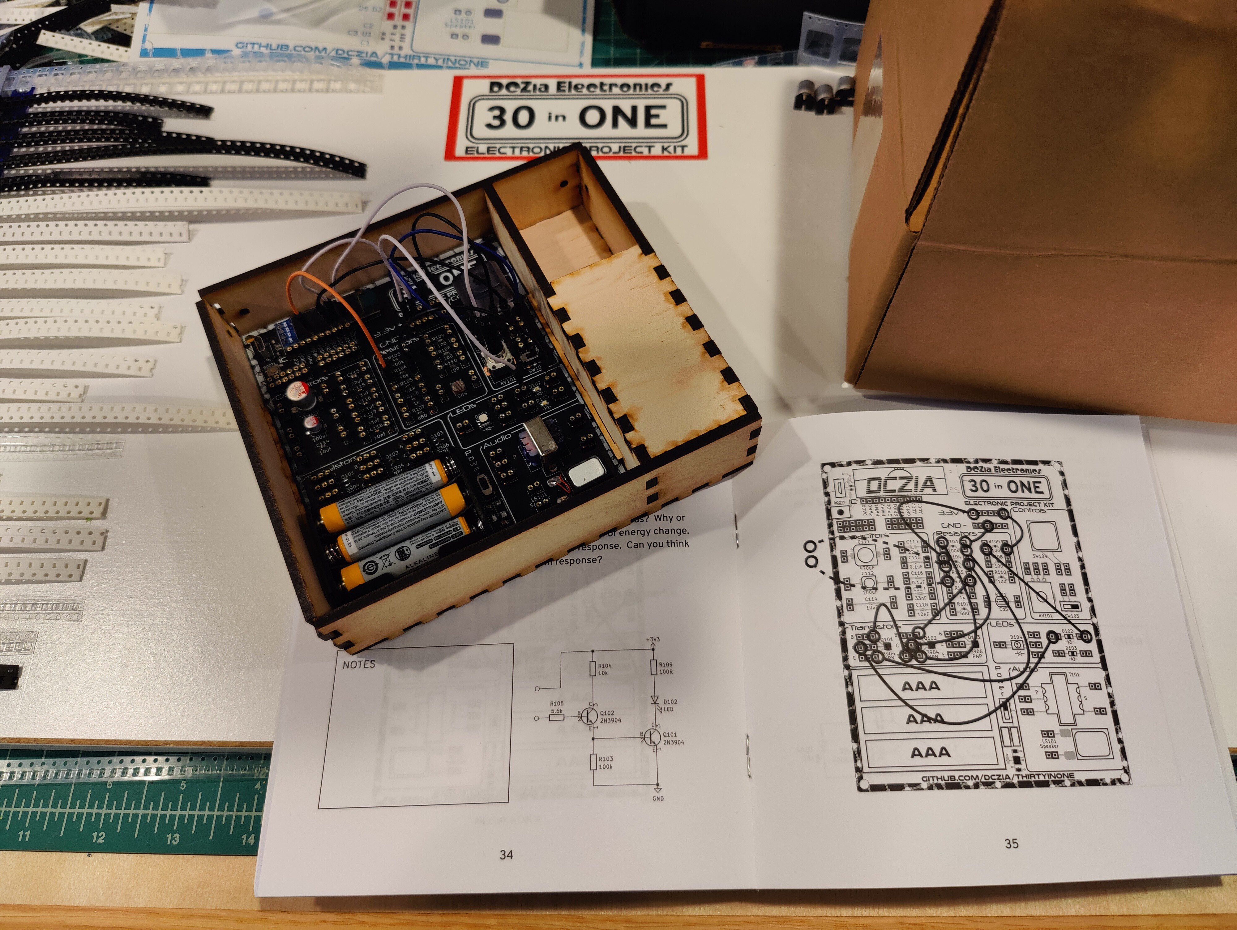
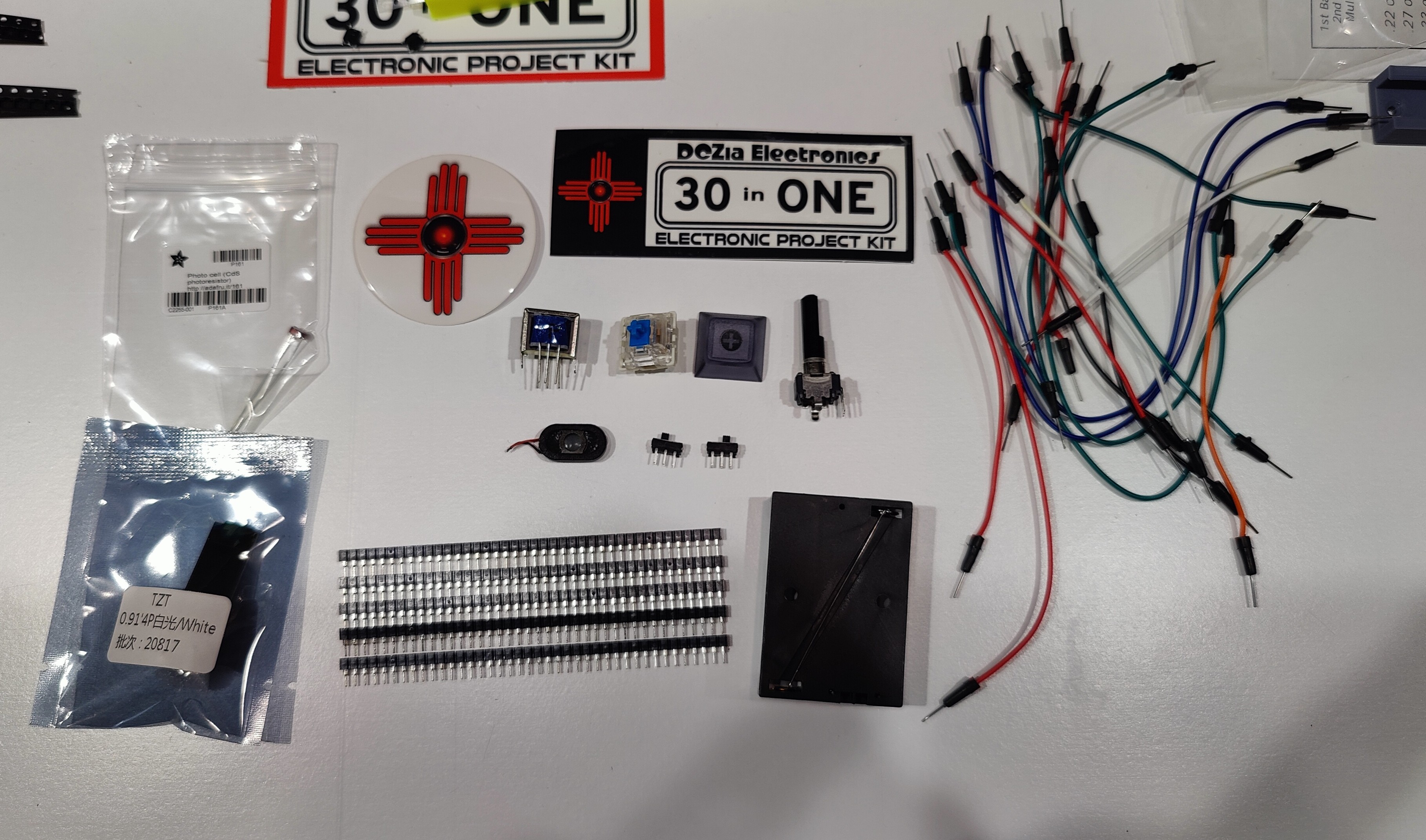
The idea behind the kit is that you have a printed booklet you start from. In the booklet, you learn about electronic components, schematics and symbols, and then you are presented with multiple circuits you can build using the kit in front of you. A diagram showing how all the wires need to hookup is set opposite the schematic. A description of why the circuit is interesting is presented, along with some questions to help you learn how to take your new knowledge and run screaming into the woods with in some new fashion.
A Circuit in Action
Take for instance one of my favorite circuits, using a standard NPN transistor to figure out the temperature. It's wonderfully simple, but it's not at all obvious how it works at a glance. Let's look at the schematic:
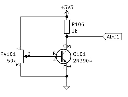
Not much going on here. So how does this work? The NPN transistor is just that, 3 regions of silicon that are 'doped' such that they are negative or positive, ie, do they have more or less electrons? You can induce a current flow through the transistor by applying a small current flow through the middle of it. In this way, a transistor can work in two modes: as a 'switch', on or off, or you as an 'amplifier', where the output follows the small current. This small current is fed into the 'base' of the transistor. The 'collector' collects electrons, and the 'emitter' emits them, establishing a current flow. When operating as an amplifier, the transistor is said to be in the transconductance region.
But there is an interesting side effect here. The amount of current the NPN transistor passes will vary just a bit due to the temperature of the junction. Most of the time you don't care about this little wobble, but really sensitive circuits have to have temperature compensation just for this reason!
As such, we can put this to work to demonstrate the principle - we adjust the potentiometer RV101 until the output voltage is somewhere between fully saturated (3.3v) and ground. Then, heat the transistor up with your fingers. The voltage will start to change! It doesn't read out the temperature directly, and no two transistors will be exactly the same, but it does work well to determine if the temps are going up or down.
Open Source
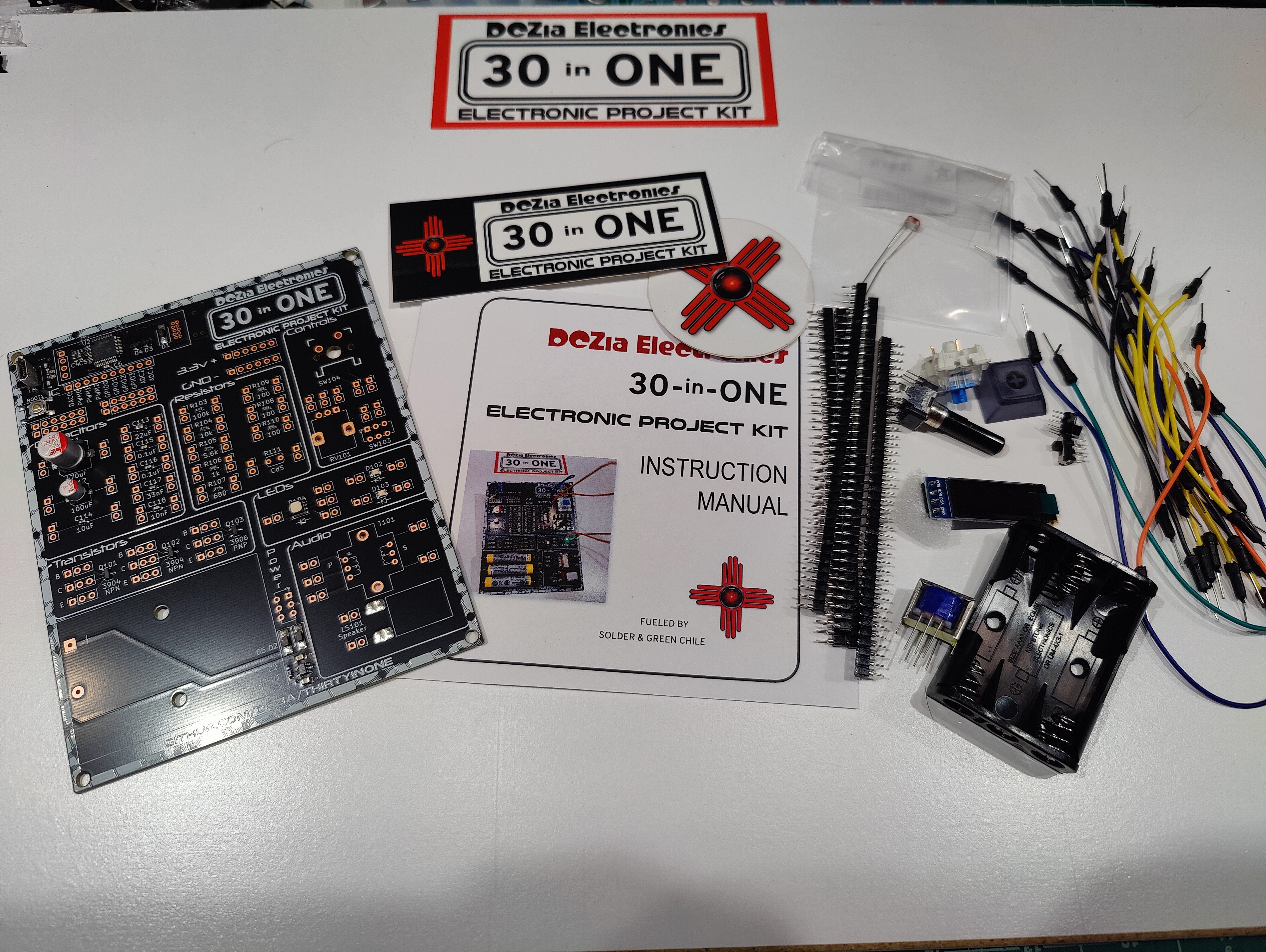
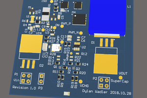
We don't just talk the talk when it comes to making things open source. Everything you see here is out in the open, licensed for you to do whatever you want with it. We even got the badge certified as being open source hardware. We want you to take what we have done and take it to the next level. Bring it to us at a con or show us what you have done online. I've even been known to give out free future badges to people who add really neat contributions.
 Dylan
Dylan
 Yann Guidon / YGDES
 Aleksandar Bradic
 joey castillo