Close
0%
0%

EL Wire Clock

An Electro-Luminescent Wire Analog Clock

Similar projects worth following
This project is an electronic model of an analog (hands) clock. It will have 12 segments of EL wire in a radial fashion to display hours and 12 slightly longer segments to display minutes. One of the wires can be seen in the photo of the back side of the board. The main purpose of the project is to serve as a project to learn a new CAD program, and the EL wire clock is an idea that I have wanted to fool around with for a long time, but never had the time/motivation.

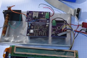
The main part of the clock is a 24 channel EL wire sequencer and power supply. A Micrel MIC4826 chip is used to convert 3.3VDC up to about 140VPP to power the EL wire. A series of 24 TLP168J Photo-Triacs switch power to the selected wires. The Photo Triacs are controlled by a discrete logic implementation of a 24 bit SPI interface that is driven by an NXP LPC1114 MCU demo board. A Trimble GPS Copernicus II GPS module in the upper right corner of the board will set the clock on power up and once a day. Input power will be 9VAC from a wall wart.

I did the electronic design and laid out the board last summer, and got the bare boards back. Due to time constraints, I had to wait until the last few days to start building the boards. I populated the power supplies (3.3V and 144V) and the SPI interface last weekend. Both power supplies work as expected. I have not tested the SPI interface yet or installed the Photo Triacs yet. I bridged two of the Photo Triacs for testing the EL wire power supply and installed a piece of the wire.

This is the first time that I have worked with EL wire, and have not found anything like a real data sheet on the wire that I got. When I built the high voltage power supply, I set the output frequency to about 160Hz. After connecting the wire, it was plain that it was not bright enough. I raised the frequency to about 500Hz and it was a little brighter, but not bright enough. Next, I raised the frequency to 1.2KHz and it is brighter, but still not bright enough. From the Micrel data sheet, it looks like 1.2KHz is about as high as I can go with this power chip. The voltage is about 144VPP or about 50VRMS. Does anybody know what voltage and frequency people are using to get good visibility from the wire? Do you get acceptable life out of the wire still?

  • Final bits

    Bharbour05/24/2017 at 18:13 0 comments

    After thinking about it, I decided not to put the GPS into this project. It would add $50 to the cost and did not seem to be worth it.

    I made an enclosure for the clock out of 0.030" aluminum and painted it black. The clock looks much more finished than a bare board stuck on the wall. At this point, this project is done.

  • Added user interface firmware

    Bharbour01/07/2017 at 16:20 0 comments

    I put the user interface code in to allow setting the clock from the buttons. The last image shows it's about 8:55. I kind of like the look of this project, When I had the wire segment test code running, it was stepping through all of the segments, fairly quickly and it had a definite retro neon look to it. Running the clock firmware, it still looks like a neon clock, like something I saw when I was a kid.

  • Wire Guides in, New Power Supply

    Bharbour01/06/2017 at 18:21 0 comments

    A friend printed the wire guides that I designed to hold the EL wire straight, and I installed them and was able to put all the wires in. It was still a fiddly process, but it was possible to do, and the results look pretty good. I installed the opto-triacs to control the wires and wrote a simple sequencing test program. All the wires light up.

    I replaced the MIC4826 with a commercial inverter module designed to drive EL wire. The brightness on the wire is now acceptable and the opto-triacs switch OK at the 3KHz output frequency of the inverter. In order to make sure that the inverter always has a load on it, I put a circle of EL wire around the outside of the wire guides. This also accentuates the length difference between the hour and minute wires, making it easier to read as a clock.

    My plan for timekeeping is to use the 60Hz (US) power line frequency on an interrupt for the MCU. Initially,I had a 9V feed off the input bridge rectifier, before the filter cap, that is divided down and clamped with a diode to not exceed the 3.3V power supply rail, feeding a GPIO pin with an interrupt on it. When I tested it, it turned out to be a random number source, rather than a time base. I put code into the interrupt service routine that sets another GPIO line high at entry to the ISR and low again at the exit to the ISR. The GPIO line was showing 1 to 5 pulses on the falling edge of the rectifier output, and 0 to 5 pulses on the next rising edge of the rectifier output. There should have been a single pulse on the falling edge of the rectifier output. It turns out that there is a lot of fast, high amplitude noise on the rectifier output. Some of the noise is probably from the input of the 3.3V switching regulator that powers the rest of the board. Some of the noise is probably from neighbors solar inverters and some is probably from power line communications used by the utility company. The GPIO line is supposed to have 0.4V of hysteresis which I had hoped would deal with the noise. It didn't. My solution to this is to trigger an LM555 set up as a one-shot, on the falling edge of the rectifier output. The 555 resistor and capacitor are chosen for a pulse length of about 7.8mS. The haversine signal coming out of the rectifier has a period of about 8.3mS, so the 555 will trigger once per period (120Hz). The 555 output (about 9V) is current limited and clamped to not exceed the 3.3V power supply, and fed into the GPIO input. The phase accuracy on this is going to be pretty awful, but the clock shows time in 5 minute increments, 8mS jitter is ignorable! After testing with the mods in, the time is within seconds of the expected time when run over a 24 hour period. This is as close as I can get testing with the debugger.

    My plan for timekeeping is to set the clock on powerup from the on-board GPS module, then shut the GPS down and run on the powerline frequency time base. Every night at midnight, the GPS will be powered up and if a fix is availible, the on-board time will be corrected.

    I wrote and module tested the UART device drivers earlier in the week. The next step is to carve up my NMEA parser code to strip out parsing for the messages that will be ignored or disabled. Having the GPS time available will be a good way to check the accuracy of my power line cleanup method.

  • Progress on several fronts

    Bharbour01/01/2017 at 18:58 0 comments

    The chip that I had hoped to use for the EL wire power supply is not going to work. It puts out about 75 VRMS as measured on an RMS meter and checking with a scope, this is correct considering the duty cycle and the wave shape (close to square wave with big dead times). Unfortunately, it is not enough.

    I looked at a commercial EL wire inverter and it is putting out about 130VRMS (300VPP at 3KHz) and it is fairly sinusoidal in appearance. The voltage slew rate is high enough that it may prevent the opto-triacs from switching off as the voltage goes through 0V. It is still worth trying the commercial inverter, if it does not allow the opto-triacs to switch off, I can continue with building my own inverter.

    Numerous sources say that you are not supposed to disconnect the load from an EL wire inverter while it is powered up. My solution to this is going to be to put a segment of wire on the board that is always connected, so the inverter will never be run without a load. The "always on" segment will be long enough that the smaller loads from the wire segments should be negligible.

    When I designed the board, I planned to cut the EL wire to the proper length and strip both ends. The center (driven) end of the wire would have both leads soldered to pads visible on the board. The outer end would have the center conductor soldered to a pad just to keep the wire in place mechanically. After stringing a couple of wires in this way, it is a huge pain to get the lengths accurate after stripping, and the wire will not lay very straight. It looks bad. The new plan is to print some little guides that will be glued to the board and the wire will only be connected to the board at the center end. The guides will have a channel for the hour and minute wires and keep the wires straight. This cuts the number of prepared ends on the wire in half so it should be a lot less work. It should look much better as well.

    I started the software development so that I could test the SPI slave interface that drives the opto-triacs. It is a 24 bit slave interface built from 6 octal D flip flops, using three configured as a shift register and 3 configured as an output latch. It works as expected. A series of switches and buttons are on the board to handle manually setting the clock and setting the time zone when the GPS sets the clock. The switches and buttons go into GPIO inputs on the LPC1114 board. I wrote and tested the code handling the switches over the weekend.

  • Experimenting with the EL Wire

    Bharbour12/15/2016 at 03:37 0 comments

    I am trying to get some brightness out of the EL wire, and 140VPP is not sufficient. Tonight, I hooked a step up transformer up to the output of my old HP sine wave generator (200CD) and was curious what voltage I could get out of the transformer and how frequency dependent it was. The transformer is a mains power transformer (with the generator hooked up to the low voltage side), so it is happiest around 50 - 150Hz.

    Watching the brightness of the EL wire, it appears to be mostly voltage dependent and not as much frequency dependent. With the output voltage around 400 to 450VPP and the frequency around 140 to 150Hz, the blue EL wire was visible in a brightly lit room. In a dim room, it looked great. Tomorrow, I will go see if I can find an audio transformer that will deal with higher frequencies better, so that I can try raising the frequency above 180Hz.

    The photo-triacs that I am using for driving the wires will handle up to 600VPP, so 400 to 450VPP is not totally crazy.

    It looks like this project is going to need a completely different high voltage supply bubble gummed in to work at all.

View all 5 project logs

Enjoy this project?

Share

Discussions

Shane wrote 10/15/2018 at 00:59 point

I have a project using microchip HV809 and a discrete boost converter, I am able to run a meter of EL at 360Vpp and 2.5khz.  I can help you make that work if you like.

  Are you sure? yes | no

Bharbour wrote 10/15/2018 at 01:52 point

Thanks! I was looking at your project. I like your approach of separating the high voltage generation from the output frequency generation.

This project is pretty much done for me. The main reason that I did it was that I needed a project for learning a new CAD system and this one had been floating around in my head for a while. Cutting and dressing 24 pieces of EL wire turned out to be a big pain. I think I wound up replacing/redoing about 1/3 of the wires because they shorted or I cut the drain wires during stripping.

  Are you sure? yes | no

Keith wrote 01/03/2018 at 21:30 point

I have a biscuit tin full of GPS modules, the size of a postage stamp. I can send a few your way. Not so keen on digital mimicry of analog clocks, because time is a continuous flow not chopped into ticks. You might need 60 wires to provide 1-second jumps of a second hand. I'd be inclined to have a single wire sweeping through the minute. One TV show I watched used a 7-segment decoder to switch mains triacs to drive flourescent tubes to make a HUGE digital clock. Google "The Secret Life of Clocks" by Tim Hunkin.

  Are you sure? yes | no

Bharbour wrote 01/28/2018 at 22:53 point

Sorry I missed your comment for a while. In principle, I agree on the limitations of the digital mimicry, but clocks are a special niche. I rarely care about what time it is to better than 5 minutes. I seriously thought about making it tell time in 15 minute increments, but that seemed too coarse. The project was as much about messing with driving and controlling EL wire as having a finished clock.

  Are you sure? yes | no

Keith wrote 01/29/2018 at 00:34 point

True, having fun with stuff is more important than the time. I recently thought about using the LED strips from modern LED 'filament' bulbs to make modern equivalents of the numitrons. That will need some fairly high voltages, about half mains voltage depending on how the strips were wired, but the current can be much lower. I don't want a clock as bright as a light bulb :-)

  Are you sure? yes | no

oshpark wrote 01/07/2017 at 00:53 point

Great project idea!

  Are you sure? yes | no

Bharbour wrote 12/16/2016 at 15:25 point

I got a small audio transformer to continue trying to characterize the drive signal vs brightness on EL wire. My previous attempt used a big mains transformer to step up the output voltage of a signal generator. The mains transformer would only let me test a narrow range of frequencies from about 50Hz to about 150Hz. The audio transformer let me test the frequency range from 750Hz to 3KHz by adjusting the output level of the generator to keep the voltage on the EL wire constant (as seen on an o'scope). I don't have any optical instrumentation, but from looking at the brightness of the wire at 750 Hz, 1.5 KHz and 3 KHz, with the voltage adjusted to 150 VPP (sine wave) the light output seemed pretty constant. 

This is not what I was expecting at all. I was expecting to see the light output increase linearly with each frequency step. My first guess is that the brightness/frequency curve peaks below 750 Hz.

  Are you sure? yes | no

Jan wrote 05/26/2017 at 10:45 point

Very nice project! Clocks of any kind always spark my interest.
I used some EL wire and foil a few years ago. There are many inverters which feature brightness controll as well (http://www.el-light.de/start.htm?el-schnur_(leuchtschnur,_el-wire).htm - http://www.okled.cc/9vdc-dimmer-inverter-p-516-1123.html). Maybe you could buy one and take it apart...

  Are you sure? yes | no

Martin wrote 12/15/2016 at 16:21 point

I experimented with different ICs, one with a similar structure as the MIC, HV857 and another one with an output structure which allowed a grounded load. But this was very difficult to obtain and especially at 5V supply (vs. 3V3) very sensitive to short circuit or ESD or fast rising of supply, especially at it's maximum of 200Vpp  it had a tendency to self destruct. I am not sure if it is still available. The HV857 can do 200Vpp and 1kHz. In my case also the power (lit area and stray capacitance) was an issue.

I am sorry I can not recommend any specific IC, especially with respect of maximizing brightness. This was only for keyboard night-time illumination.

I also experimented with ready made transformer modules, mostly simple fly back oscillator devices.

A sine wave has the additional advantage of reducing audible noise or better whine, if you go into the kHz range. But I think if you really want to drive it that high for good daylight visibility, the life expectancy will not be great. I would not go much about something like 110V_RMS (~300V_pp). But you can do some destructive testing :-)

  Are you sure? yes | no

Bharbour wrote 12/16/2016 at 01:13 point

Thanks for that part number. I just looked it up on Digikey, and they have it in stock. It is also pin compatible with the MIC4826. Both chips were designed by different companies that have both been bought up by Microchip.

  Are you sure? yes | no

Martin wrote 12/15/2016 at 09:17 point

140Vpp is just 70Vp or 50V RMS. I used also 200Vpp (70V_RMS) and think you could go up to 100V_RMS. But my chip did not go higher. I know that somebody went up to 8kHz too get sufficient visibility on movie cameras. I also did already overdrive an EL transformer/converter for 12VDC input from Spark Fun (The big one with about 3 to 4cm length) with 22V primary. It got a little loud, but not really hot. I think it had 2kHz. So there is some margin :-) Your EL wires only have a 1/12 duty cycle in the clock.


I know that somebody also tested small mains transformers up to 15kHz. You do not need a special audio transformer, as you do not need good linearity.


Frequency probably increases brightness more or less linear, as it increases the current. The EL is similar to a lossy capacitor. Voltage increases power quadratic as it also increases current proportional.

  Are you sure? yes | no

Bharbour wrote 12/15/2016 at 15:56 point

What chip were you using for your supply?

The (sort of) linear relationship between brightness and frequency is what I was expecting when I started this. Raising the frequency with the MIC4826 well above 180Hz definitely increased the brightness. 

Since I am bounded on the upper end of voltage by the rating on the photo-triacs, raising the frequency to get more brightness would be good. Also, a sine wave AC would be better for the triacs, because fast rise times will false trigger them. I am pretty sure that they were designed for phase modulation of mains power, rather than switching KHz range stuff.

  Are you sure? yes | no

Similar Projects

Does this project spark your interest?

Become a member to follow this project and never miss any updates