tinkerzone
-
Final Thoughts
01/23/2017 at 03:31 • 0 commentsSo the PiKelet project is almost at an end. I have achieved what I was aiming for, wiuth a few minor edits. It now boots into the pixel desktop without any issue. The USB hub works fine to power a keyboard and mouse. At this point it can be used as a complete Raspberry Pi Computer running Raspbian.
It is a useful, rugged piece of hardware that is flexible enough to be used for several purposes. I am not sure what the final use for the PiKelet will be. But it is WiFi connected and can be connected via the uart. I will add some code to make the status indicator LED more useful. I hope this build log will help someone in a future project. -
First Boot
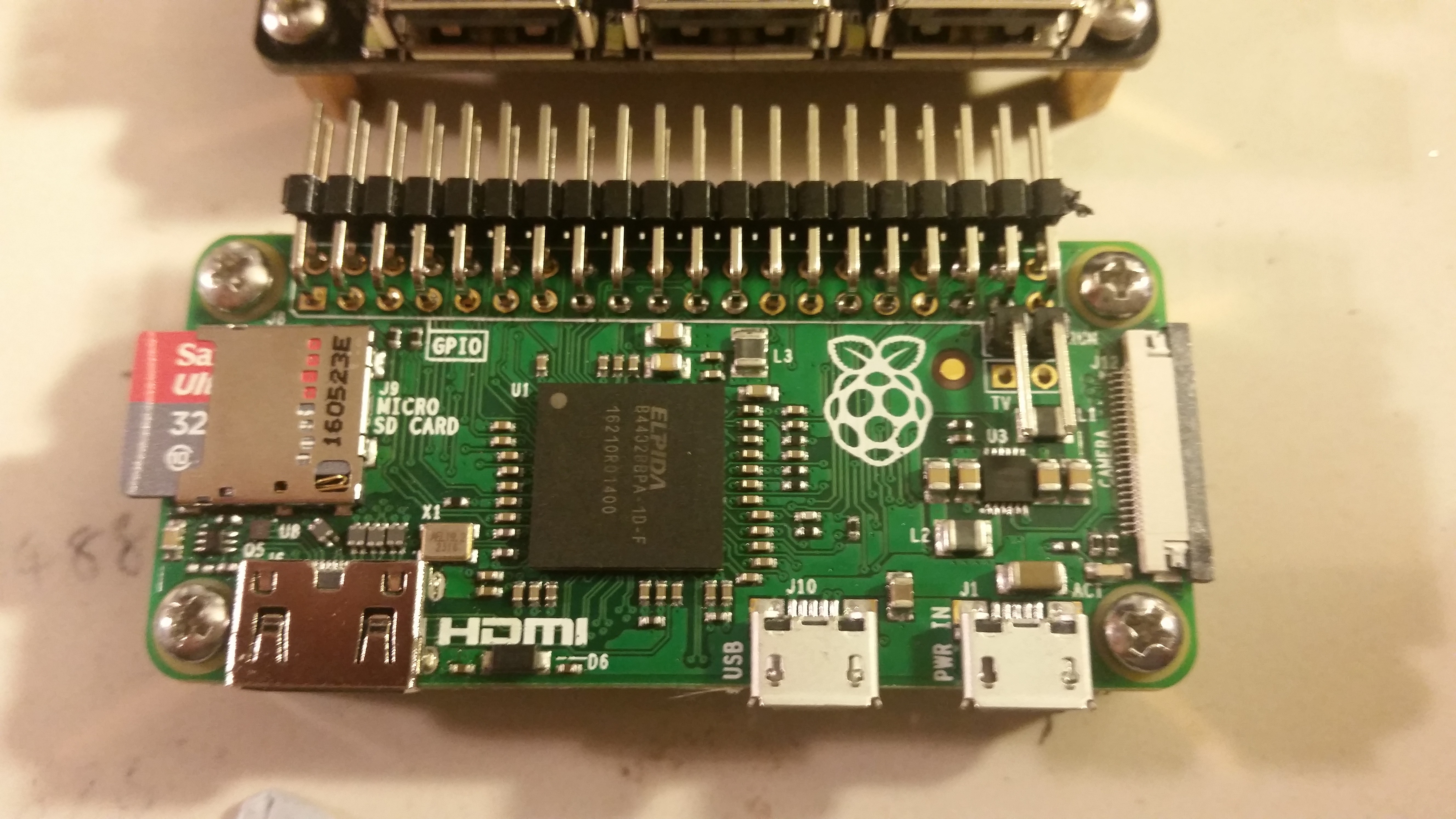
01/23/2017 at 03:18 • 0 commentsThe Pikelet is currently running a fresh install of Raspbian Jessie with Pixel version 2017-01-11 on a sandisk 80Mbps 32gb micro sd card. The latest version of Raspbian cna be downloaded from: https://www.raspberrypi.org/downloads/raspbian/
A few minor tweaks were made on the first boot.
The first step was to console in I consoled in via the USB port connected to the Uart module. My settings were:Serial Line: Com19 (yours will be different)
Speed: 115200
Connection type: SerialAfter entering the username and password I was presented with the PiKelet's command line.
Using sudo raspi-config I expanded the file system.
I also used the advanced option to change the device name to PiKelet.
WiFi was setup with the help of the guide produced by Adafruit: https://learn.adafruit.com/adafruits-raspberry-pi-lesson-3-network-setup/setting-up-wifi-with-occidentalisAt some point I may choose to change the settings to give a fixed IP address, rather than assigning via DHCP. This is useful if you ssh into the pi zero via WiFi as you will always know the IP address (provided you write it down) of the PiKelet.
The next step was to setup the RGB indicator LED. During hardware setup I connected the RGB segments to Raspberry GPIO Pins 19, 20, 21 respectively (BCM numbering). On first boot they shined a very light aqua colour cause by a small amount of current leakage through the pi. I decided that (for now) i simply want the indicator LED to shine green once the pi has booted. The following steps were made:
a new folder was created at ~ called Scripts and we moved to that folder:
cd ~
mkdir Scriptscd Scripts
Then a new python file was created:
sudo nano bootscript.py
A few lines of code were added to set GPIO pins 19,20, and 21 pins as outputs, turn 19 and 21 High (i.e. off for a common Anode led) and setting pin 20 low (Green on).
#####################
import RPi.GPIO as GPIOGPIO.setmode(GPIO.BCM)
GPIO.setwarnings(False)
GPIO.setup(19, GPIO.OUT)
GPIO.setup(20, GPIO.OUT)GPIO.setup(21, GPIO.OUT)
GPIO.output(19, True) ##As it's a common ANODE LED this turns the R segment offGPIO.output(20, False) ##As it's a common ANODE LED this turns the G segment on
GPIO.output(11, True) ##As it's a common ANODE LED this turns the B segment off
#######################
ctrl x to exit hitting save.Then we moved to /etc to edit rc.local:
cd /etcAnd open rc.local for edit:
sudo nano rc.local
A pair of lines were added to rc.local to run bootscript.py on startup:
cd /home/pi/Scripts
sudo python bootscript.py
ctrl x to exit hitting save
The result is that the status indicator will turn green once bootscript.py runs.
Future edits will modify it to turn green once WiFi is connected, or red if WiFi isn't able to be connected. (If anyone would like to suggest a code snippet for this, it would be msot welcome). -
Final hardware setup
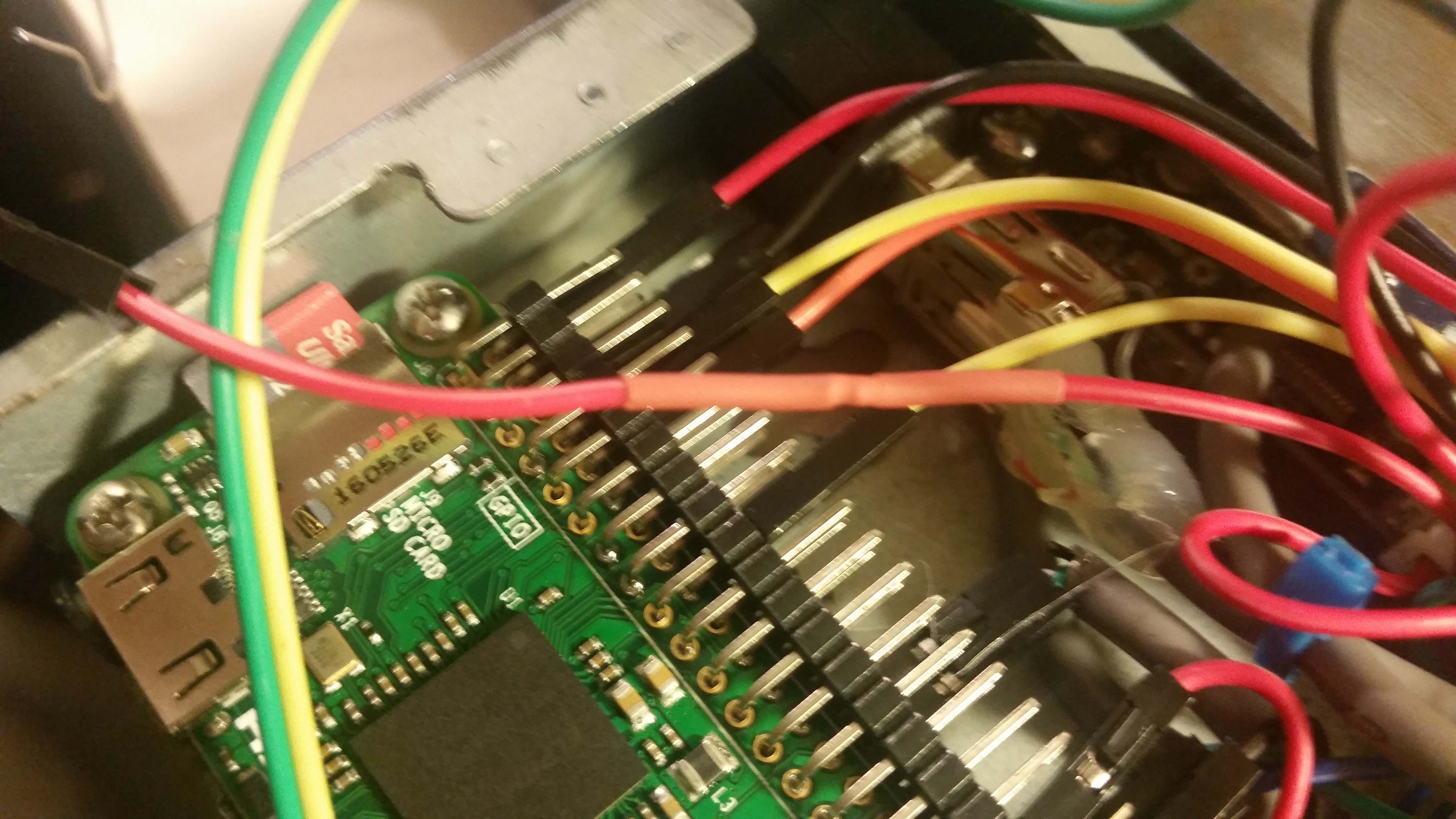
01/23/2017 at 03:09 • 0 commentsWiring it all together was pretty easy. Only one setback occured when I realised the positive lead for the power lead was not long enough to reach the 5v port on the pi zero. A quick cut, solder, and heatsink another 3cm of cable fixed the problem in a couple of minutes.
![]()
![]()
![]()
-
How to fix a hole...
01/23/2017 at 03:04 • 0 commentsSo I ditched the ethernet module. That just left me with a large hole in the back of the case. I was also finding it difficult to properly wire in power with the usb cable i had hacked the end off. And the usb b mini port under the usb hubs were slightly unsightly.
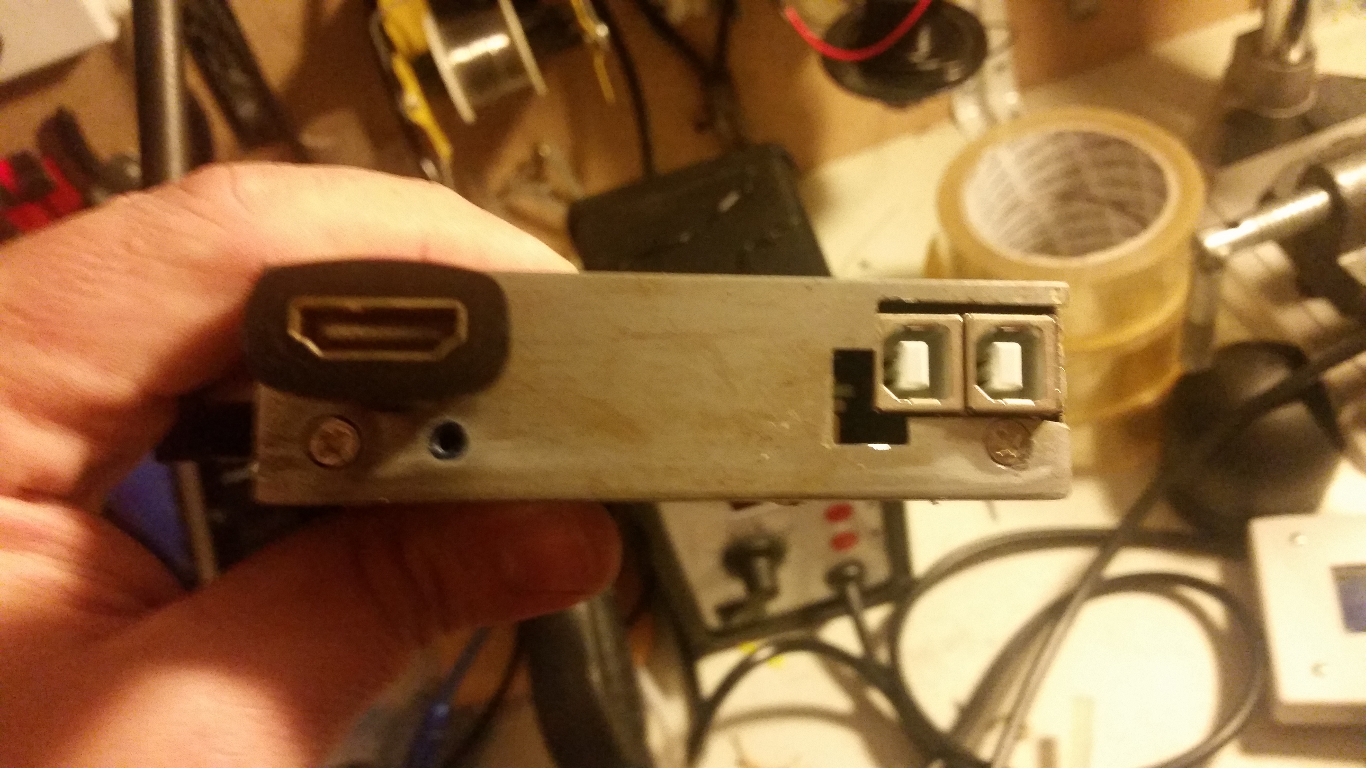
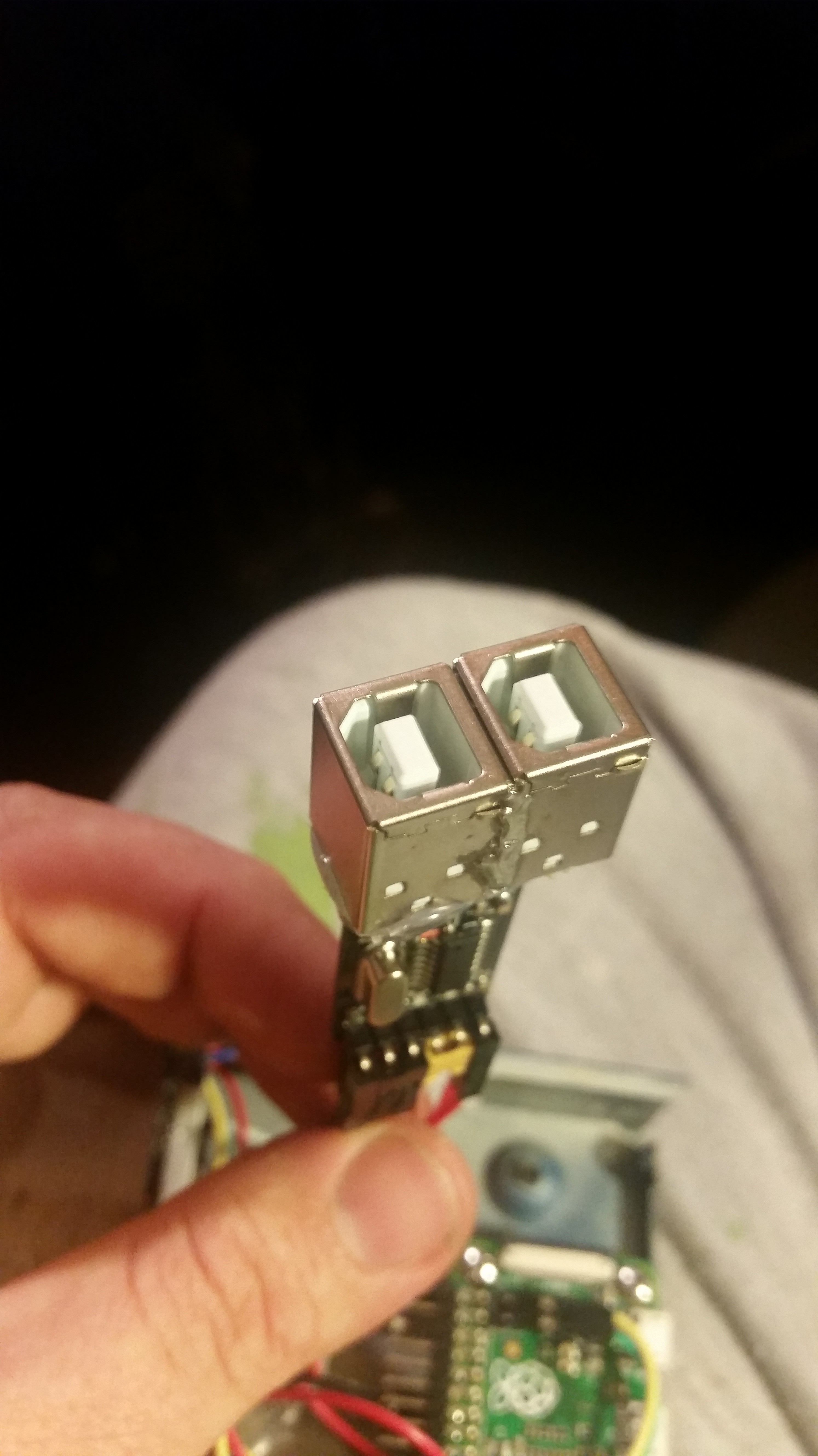
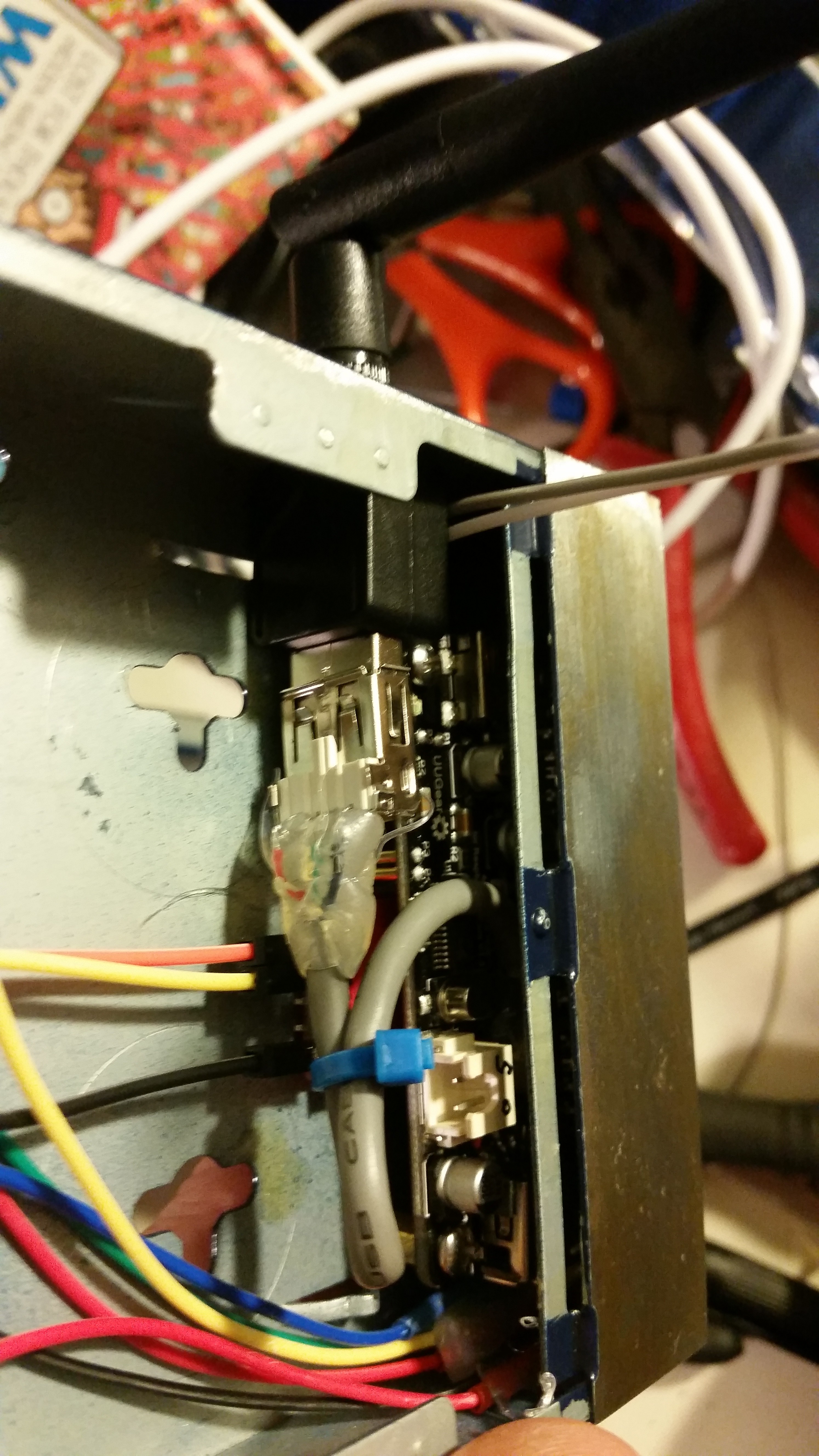
So the solution was to find something that would fit... And two USB B sockets side by side fitted nicely (with a minor case modification.
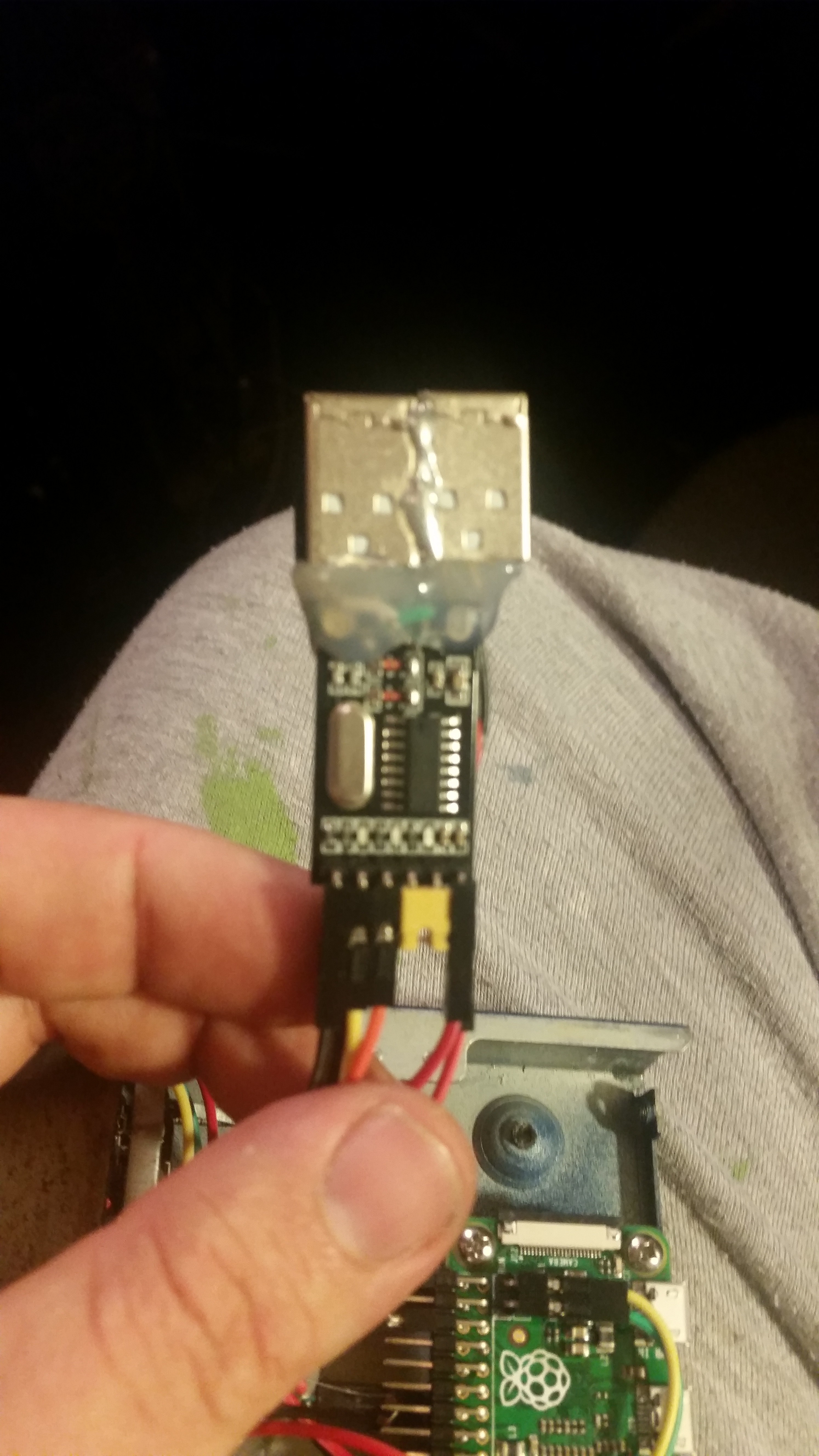
A USB uart module with a USB A module was modified to add a USB B socket, with another added in parallel with the power leads only. An extra header pin was added to the 5v and gnd wires on the underside of the uart module. The shells of the two usb sockets were soldered together. You have to file the two points to solder first, otherwise the solder won't take. Once again, hot glue was added to make it mechanically robust.![]()
![]()
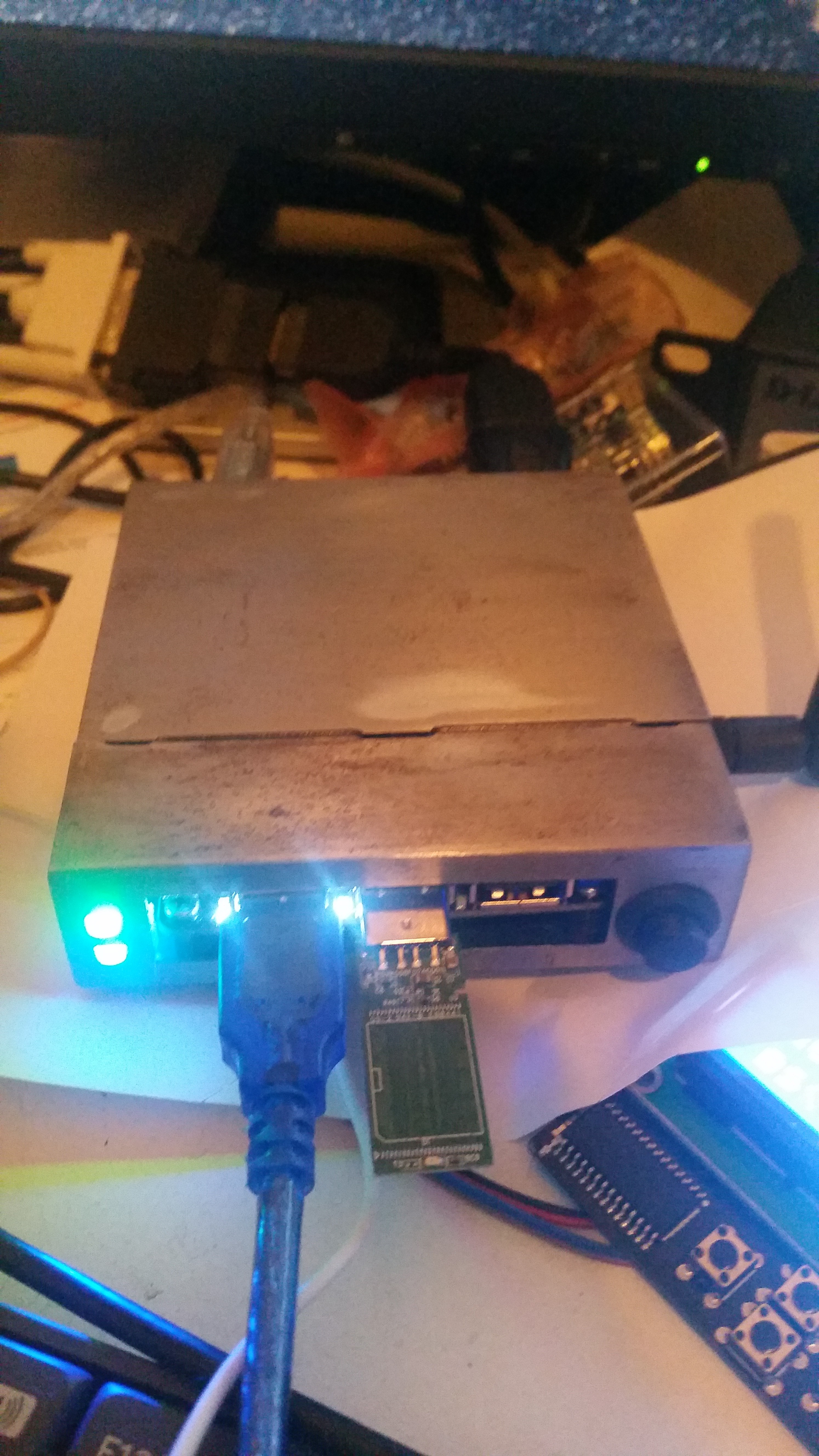
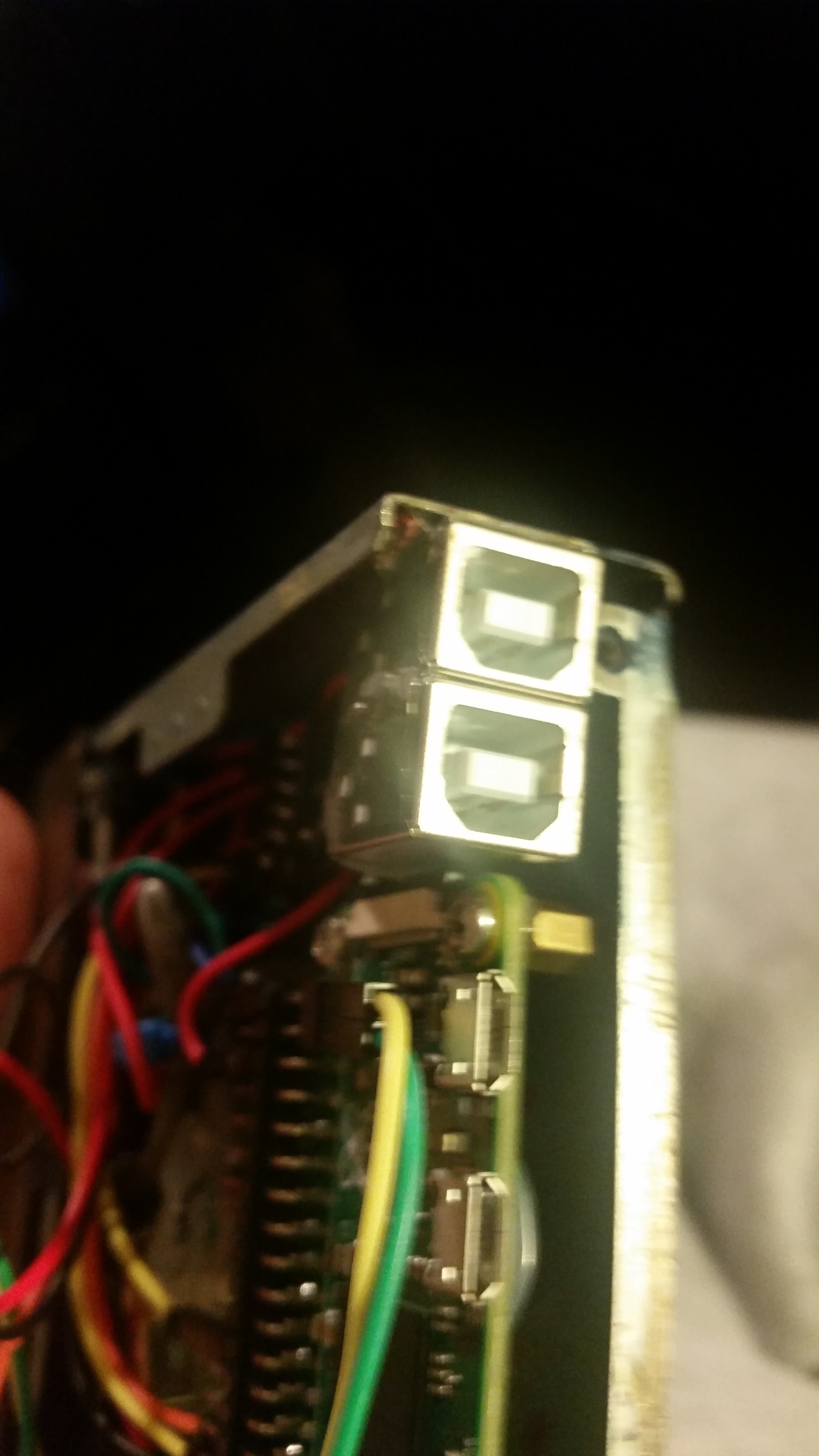
Once the modified USB uart module had been finished, I again soldered it to the steel case. It required getting the iron up to a very hot 480 degrees c.
![]()
-
A slight setback...
01/23/2017 at 02:52 • 0 commentsSo I had another slight setback. Did the final install to set things into place. Turned the pi on and tried to boot. Burning smell...
Turn off, rip everything out of the case to find what happened. Find a enc28j60 module that smells odd. Clearly the issue, not sure the cause. The case is too cramped, so I decide to dump the ethernet module and just rely on wifi. I have a console in via uart, so I don't really need wired ethernet as i have wireless throughout my house. -
Doing it right...
01/23/2017 at 02:48 • 0 commentsI needed a new Raspberry pi Zero, and found a great seller in Australia that does a whole heap of raspberry pi related products: search for seller porpy1.
This time i decided that instead of soldering the pins directly to the pads I would run short wires off them to relieve the mechanical stress. After that I hot glued the whole lot to keep it protected.
![]()
![]()
-
Disaster!
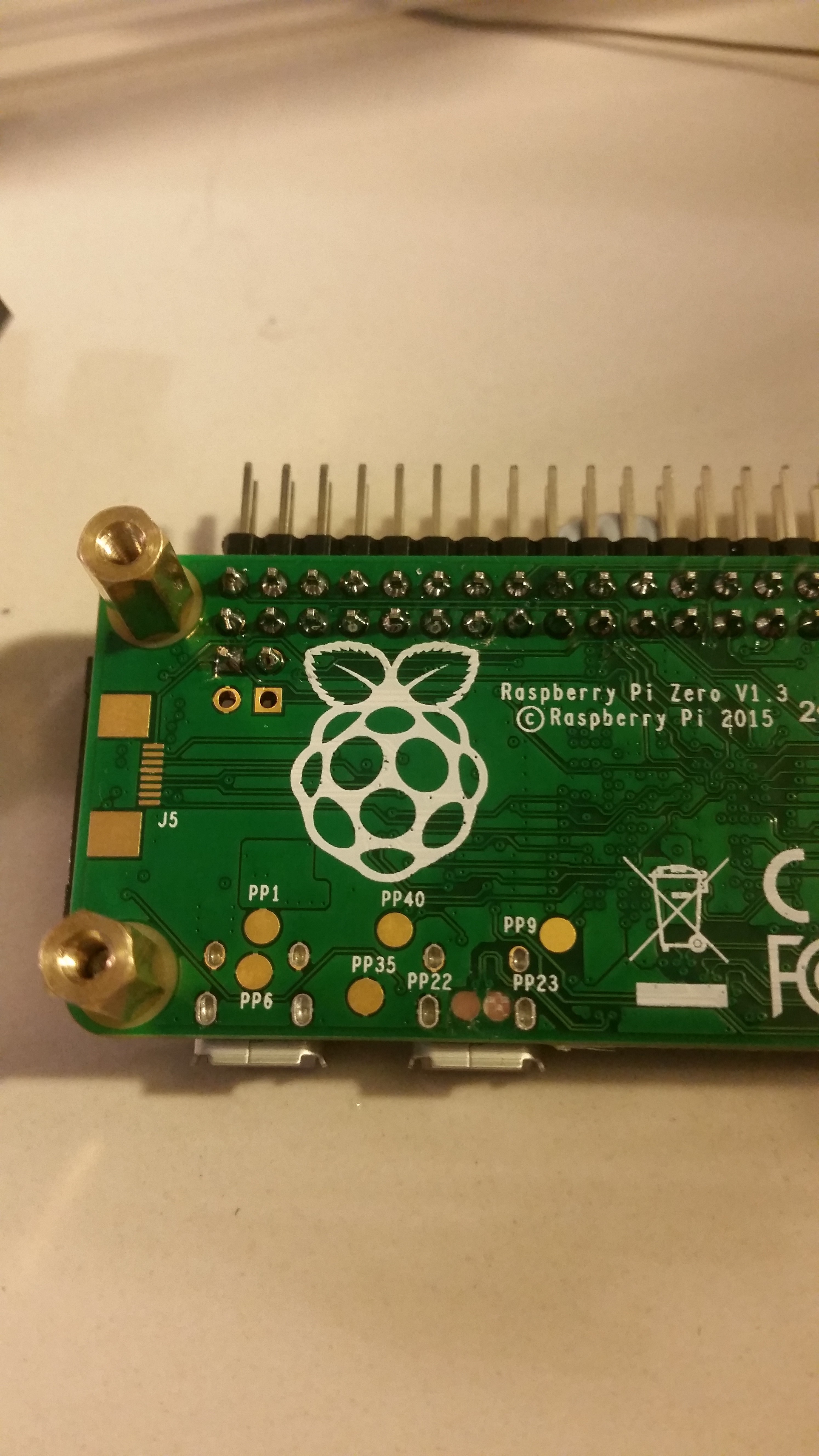
12/16/2016 at 05:59 • 0 commentsSo the utterly unthinkable happened this afternoon. I dropped the pi zero, smashing off the two headers attached to PP22 & PP23. That took away the two pads on the PCB that were attached to the headers as well. I now have no idea how I will connect the hub to the zero.
![]()
-
Choosing the Right Header.
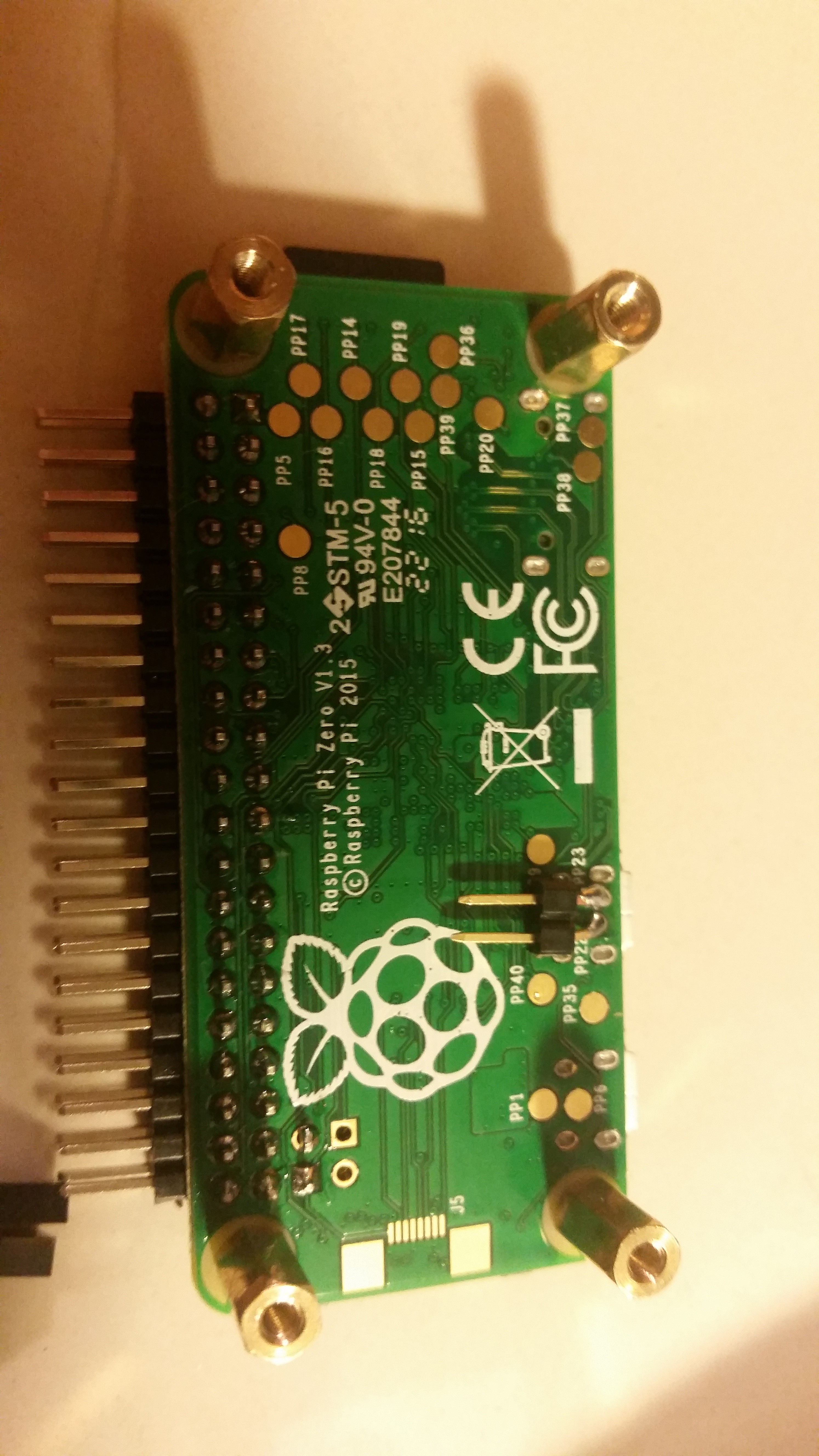
12/15/2016 at 23:08 • 0 commentsHeaders come in all manner of shapes and Sizes. I commonly keep 6 in stock for the raspberry pi that i choose depending on usage. The stock standard 2x20 Male Straight Header is usually the go to. Then there's a 2x20 Female Straight header which I usually use for pHATs. There's a right angle 2x20 Female Header that you cna use to plug the Pi Zero into a 'Motherboard' with extra peripherals. There's the 2x20 Box Header Straight that I use when breaking out the GPIO lines to a daughter Board, and similarly a Right Angle Version for when space needs. Finally, there's the header that I chose for this application. It's a 2x20 Right Angle Male Header. Height restrictions prevented me from using a 2x20 Straight Header. As i'm using the 'Run' pins, similarly a Right angle 2x1 Male Header was used because i didn't need access to the Composite Video port. Had I needed access to it, I should have broken it out to a 2x2 Right Angle Male Header.
![]()
![]()
-
Modifying the Hub Part II (The Hacker Strikes Back)
12/15/2016 at 23:01 • 0 commentsSo this issue has been worrying me for a while. How to connect the hub to the Pi Zero? Theoretically it should be easy. The Zero4U usually sits atop the pi zero and connects with pogo pins. Or you can use the inbuilt USB B Mini port. But neither that, nor the USB OTG port on the Pi Zero were actually physically accessible. I was dreading having to permanently solder the two boards together, because it makes things more difficult if for any reason you have to disconnect them.
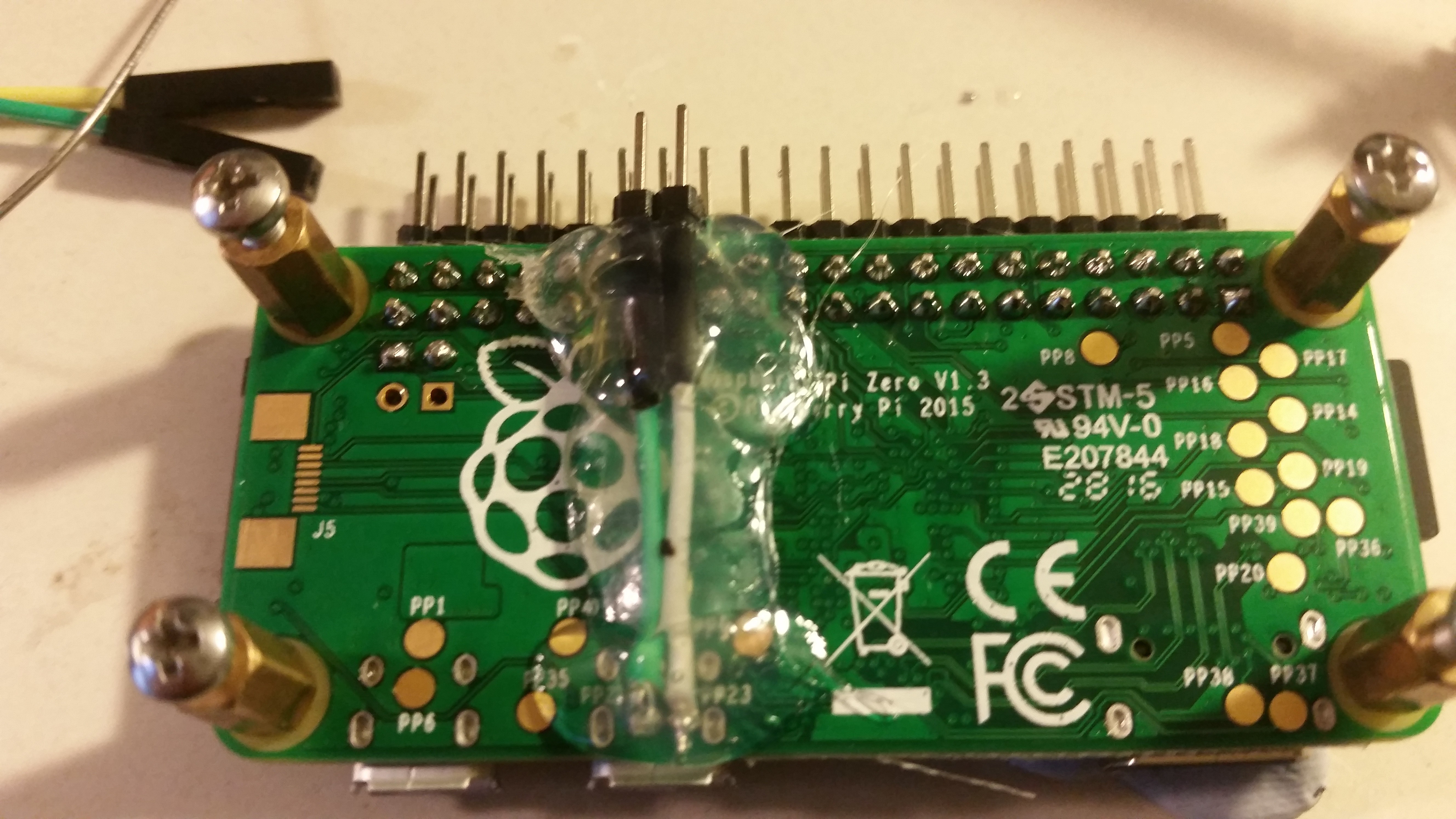
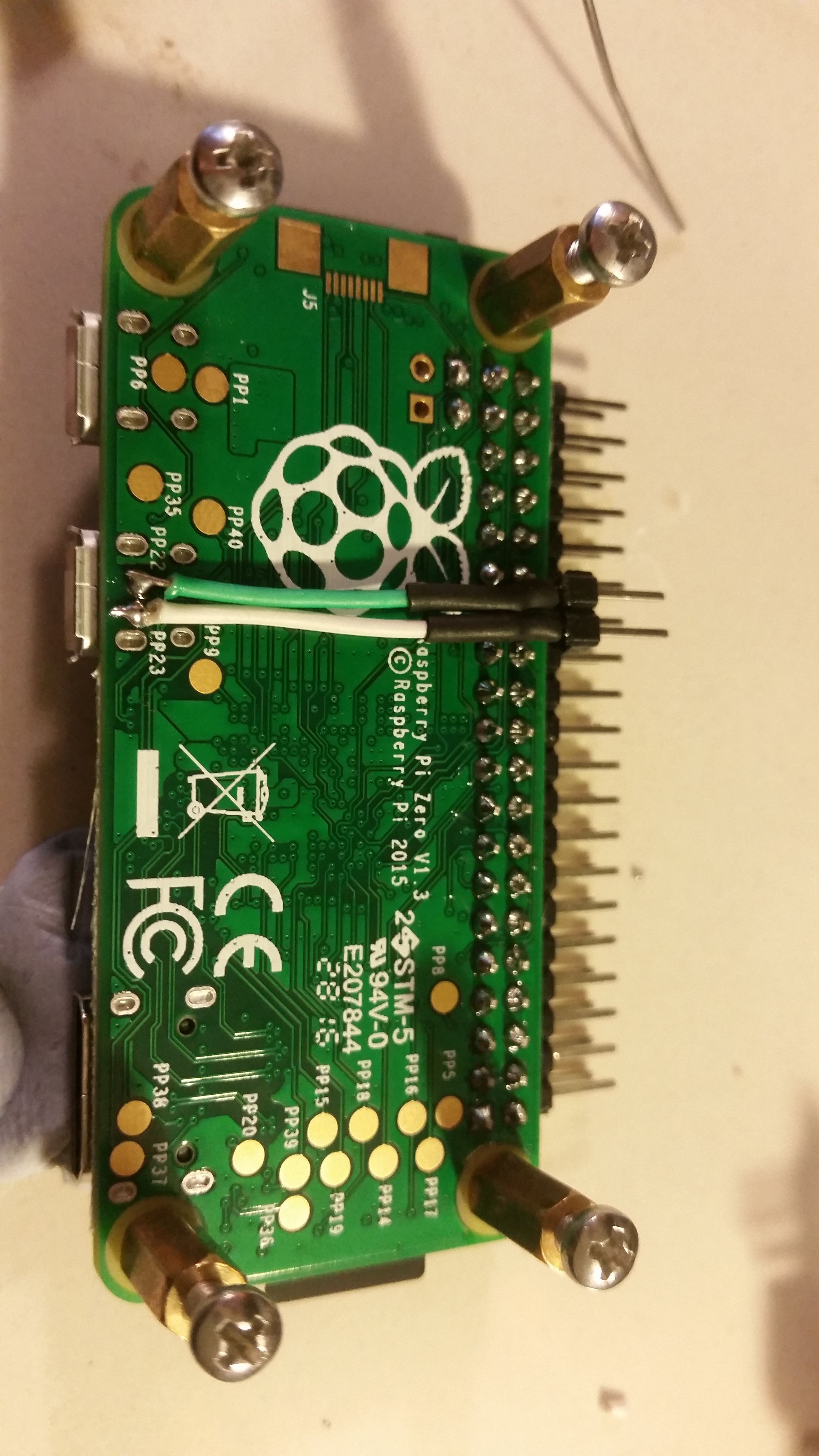
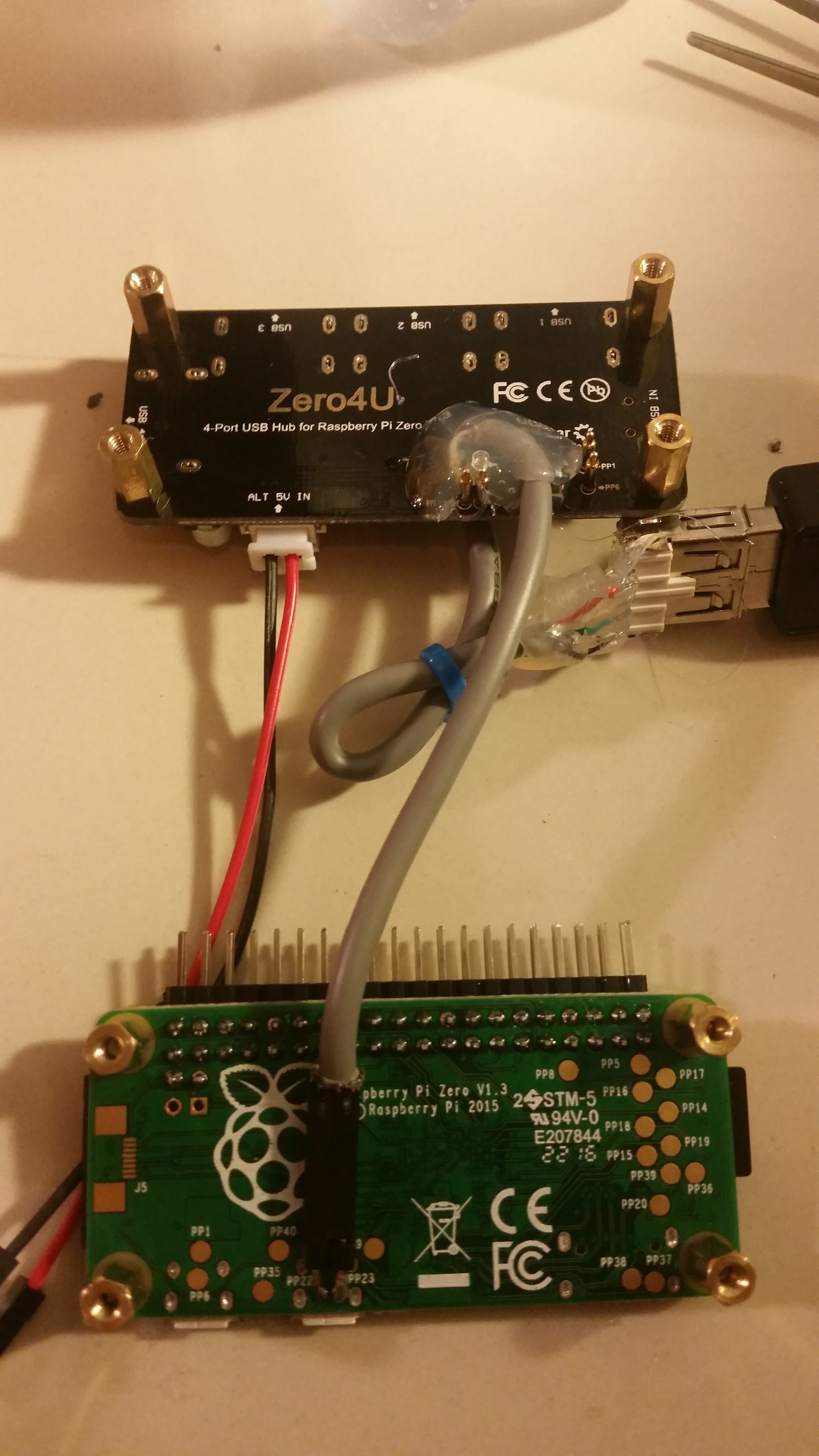
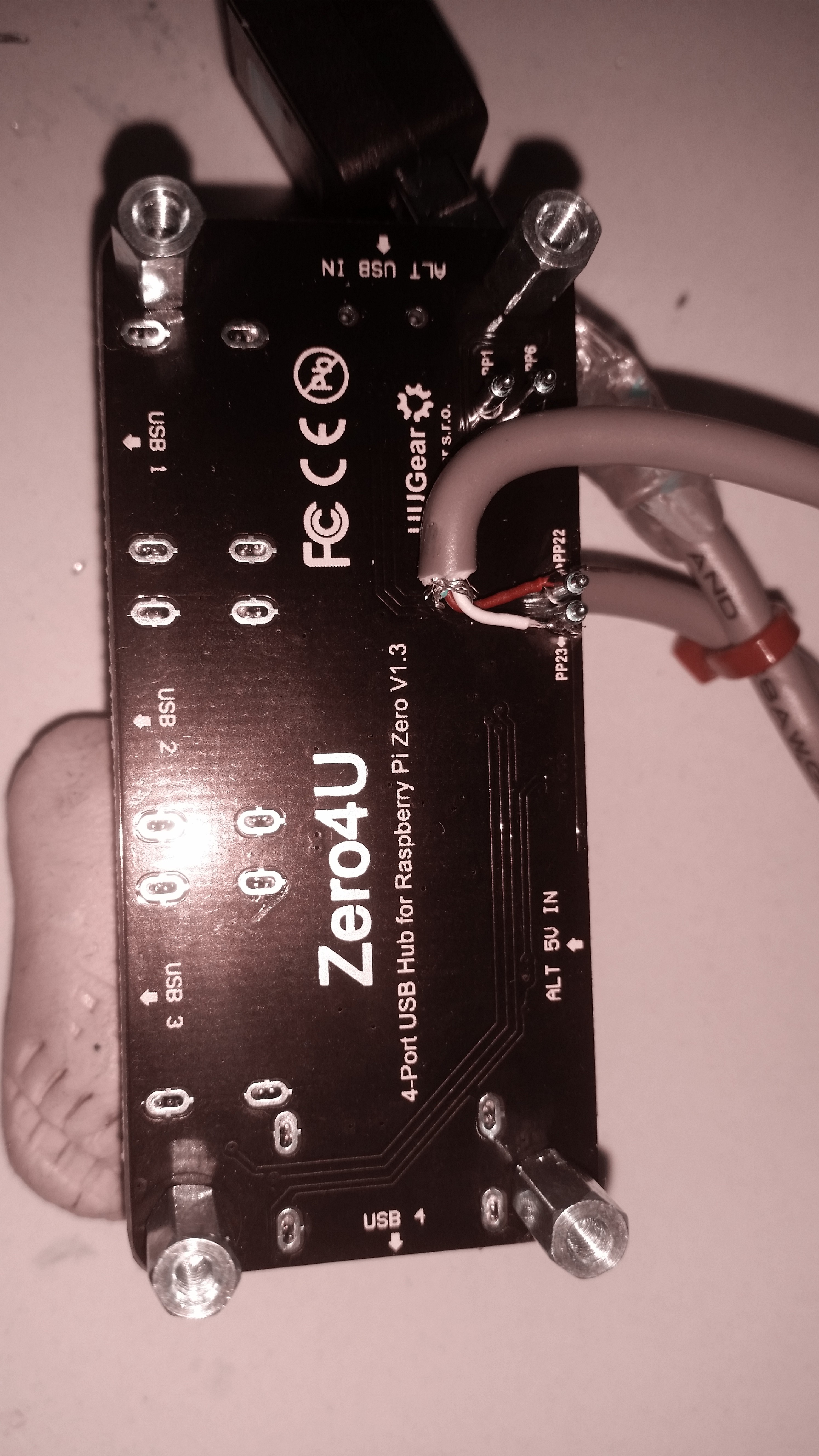
I finally realised that the two pads under the PI Zero (PP22 (D+) and PP23 (D-)) were just big enough to fit a 2.54 2x1 header if you bent the pins down and in. This allowed for the D+ (Green) and D- (White) pins to be connected to the Pi Zero via removable Dupont connectors.The D+ and D- wires were soldered directly on the USB hub. Once again they were locked down with hot glue to make it mechanically rigid.
You may note that I've only connected D+ & D- and have not connected the +5v and Gnd wires that are part of the USB standard. The Zero4u has an alternate +5f, Gnd in connector, which will be wired to the 'power distribution hub' in a later post.
![]()
![]()
-
Modifying the USB Hub Part I
12/14/2016 at 22:16 • 0 commentsSo they case is quite narrow. In fact it is tiny. So when laying out the components, it became quite clear that it'd be impossible to directly plug anything into the fourth usb slot on the hub, which isn't exposed externally. So if the USB socket won't go to the wifi dongle, make the usb socket go to the wifi dongle.
I originally stripped down an ordinary usb cable to use the plug to plug into the socket. Even by dremelling the connector in half, it still wouldn't fit. Damn, I didn't actually want to modify the hub.
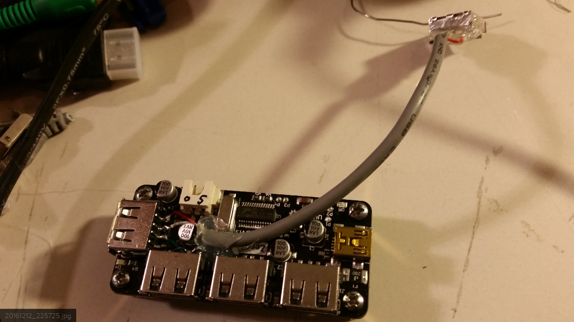
Option two involved building a little extension cable. Being careful to ensure that all the pins were wired correctly: Black; Green; White; Red. Once again, hot glue was used to mechanically secure the cable to the hub pcb to ensure no accidents would rip tracks off the hub.I made the extension cable a little long, and had to put a kink in it and tie down with a cable tie.
![]()
![]()
Pi Zero PC by Bay Networks (The Pikelet)
I acquired a great little EN104 Bay Networks 'Netgear Hub'. I decided to re-purpose it to house a little Pi Zer0.