tinkerzone
-
Blinky blinks to Blinky blink
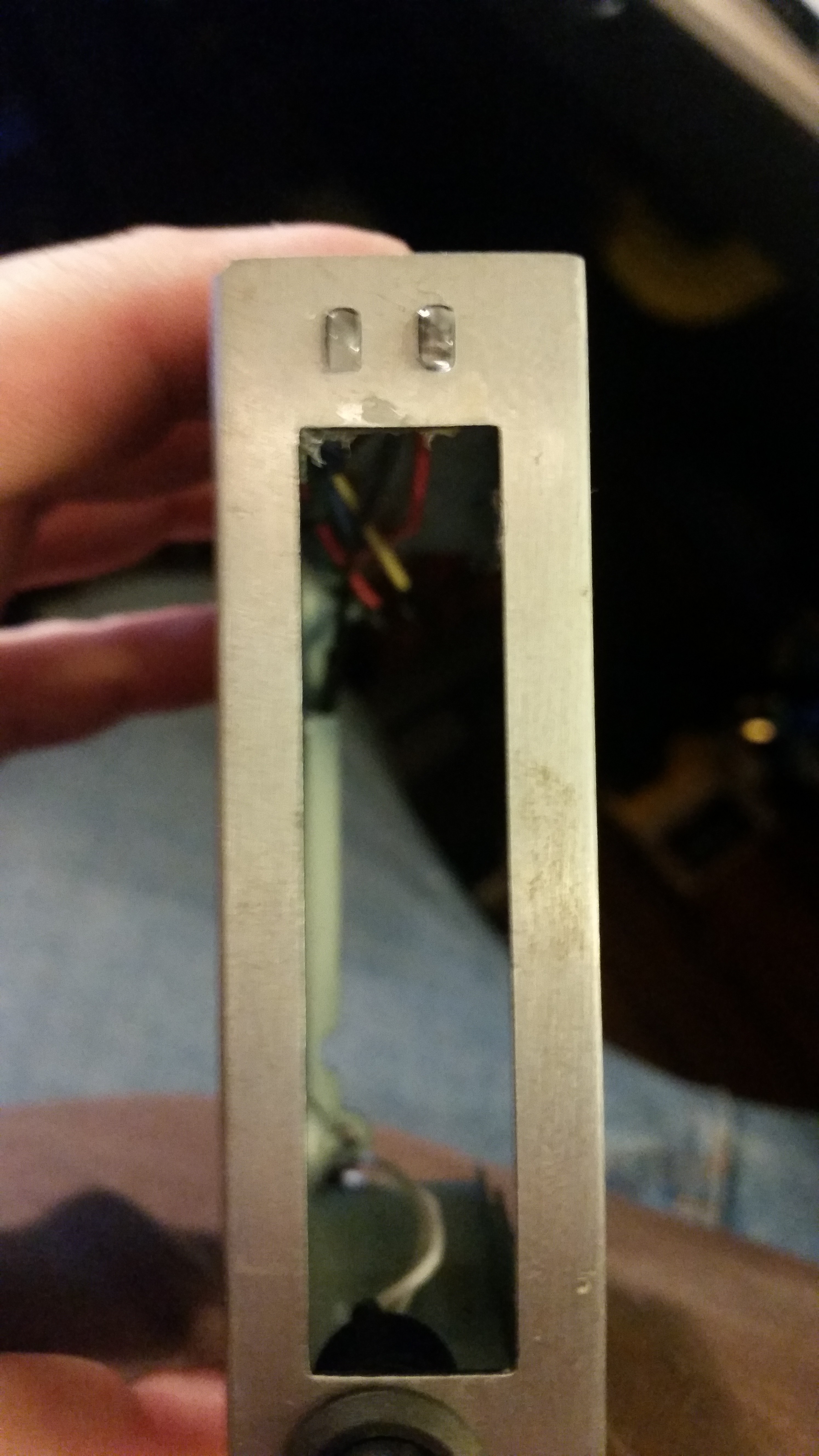
12/14/2016 at 06:24 • 0 commentsSo the case handily had two 2mm x 4mm slots for led indicators. I started by going through the led box to see if I had any rectangular leds-and I found a yellow led and a green led both 5mm. Filing down the edges of both by 1mm left me with-something pretty ugly tbh. I decided to scrap the rectangular leds.
Next step was to see what else I had: the large collection of 3mm leds I had would look really ugly in those slots. Similarly the 5mms would require more drilling, and I don't think would look terribly good either.
So i hatched the following plan. The top led is a blue 5mm which has had two sodes demelled off to form a rectangular box shape. Then the third side had 1mm dremelled off leaving a funky modern curve.
The second slot I decided should be a status indicator led of some point. I thought about mirroring the activity led on the pi zero, but soldering that is way too small for my eyes. So I grabbed a common anode RGB led, dremelled before and it fitted beautiful.
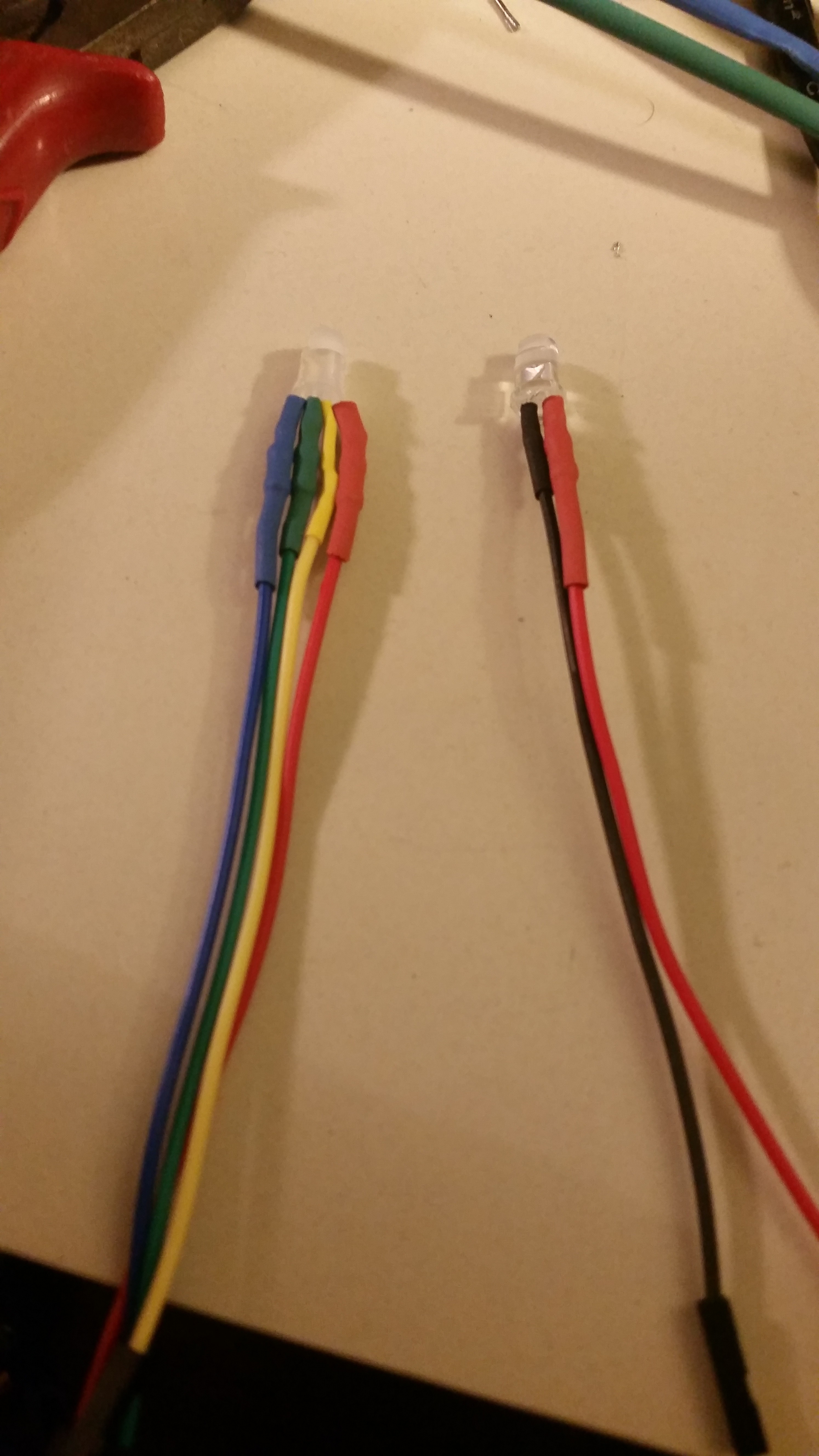
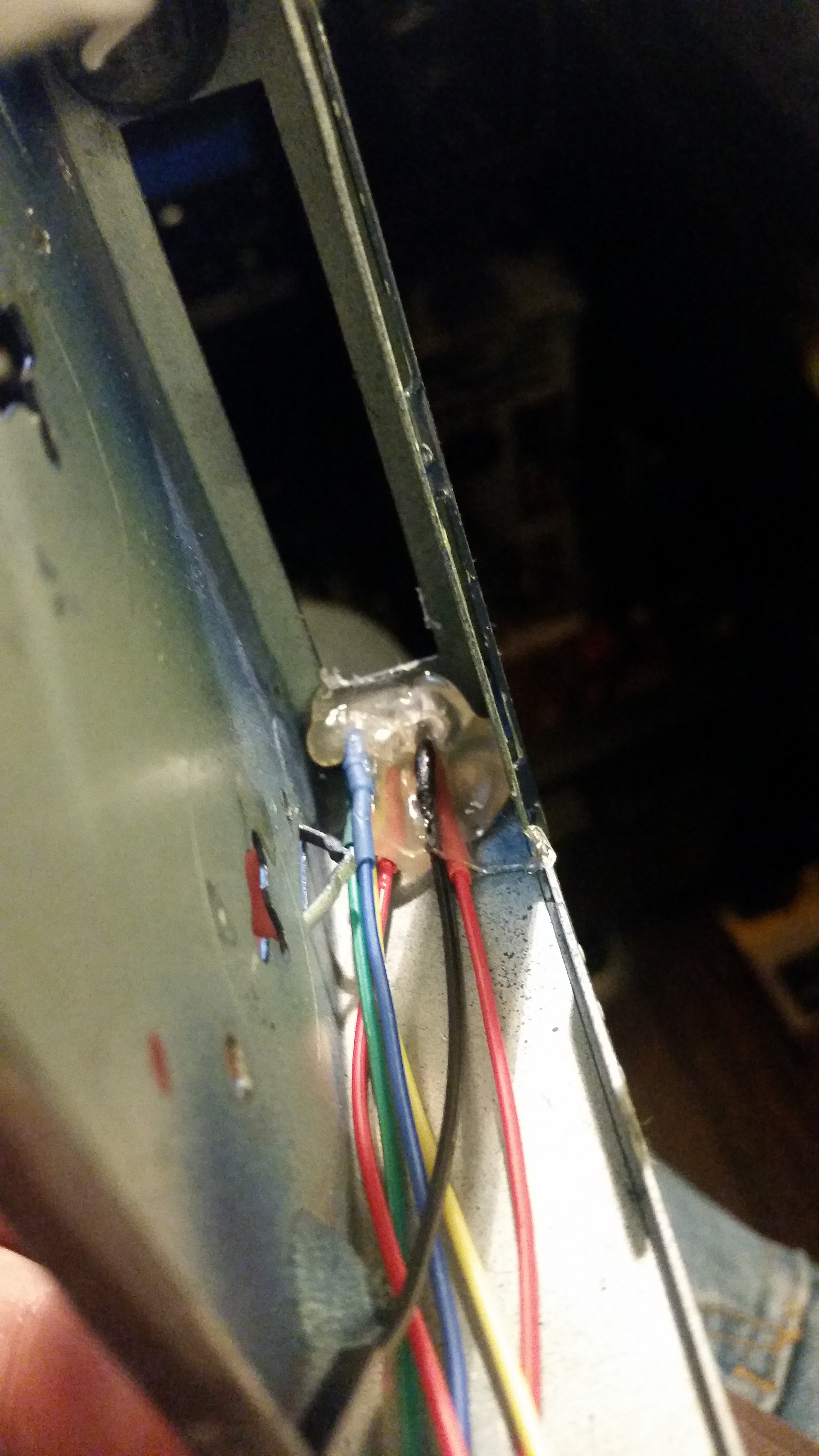
The next stage was to test the RGB led. Note: not all rgb leds are made equally. Often one colour will shine brighter for the same amount of current. After a series of tests to see how the colours mixed, the final decision was to feed Red via a 1k ohm resistor, with the G and B leds being feed through 3k ohm resistors. Your values will probably be different. Test for yourself.Given that these are to be plugged in to the pi zero board, the leds were soldered in-line with the resistors before being covered up with heatshrink. Dupont connectors on the end, obvs. As the leds are being supplied with 3.3v, I would have usually made the anode green (to match the atx wiring code: 12v yellow, 5v red, 3.3v green, but as it was an rgb led, I decided to wire each rgb pin with it's matching colour and used yellow for the common cathode. The blue power led is being driven by 5v, so was given a red anode lead with a 2.2k resistor in series.
They were mounted the old fashioned way - with lots and lots of hot glue. A neat trick to mould the hot glue is to wet your finger and push the hot glue into shape. Be careful, and don't blame me if you get burnt.![]()
![]()
![]()
-
Not all Uarts are made equal
12/13/2016 at 23:01 • 0 commentsSo this should be a simple one.
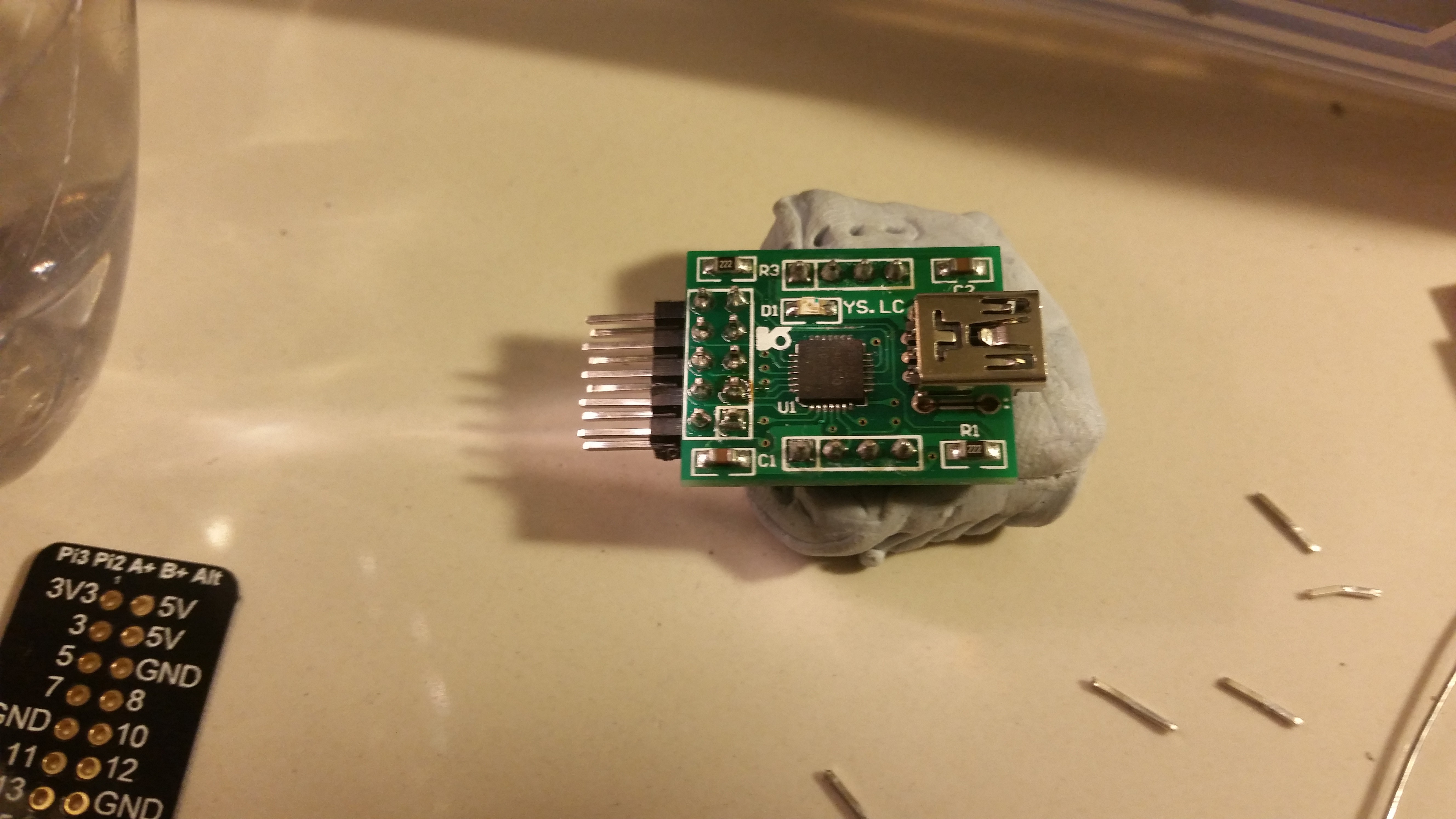
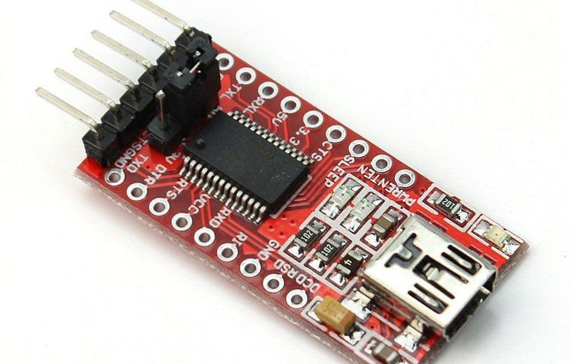
Put a uart into the case. It needs to have a micro-usb socket for neatness. So I pulled a CP2102 module out of the stock. But the case is shallow, and the header pins stood straight up. A great return to old desoldering practices were required to remove the 2x5 straight pin header and replace it with a 2x5 right angle header. As you can see from the photo, it was nicely done.
Only problem is that these modules are 5v only. And while the Pi Zero pins may or may not be 5v tolerant, I didn't have room for a level shifter. After all that work, I managed to find my 1 remaining FT232 hiding in the box of another non-completed project and used that instead. It already had a right angle header, so no mod necessary. Doh. Then promptly ordered more FT232 modules from AliExpress.
Given these modules have a 5v/3.3 volt selection made by a vertical jumper, to reduce height i cut off the header, and bridged the 3.3v with solder from underneath.![]()
![]()
-
Case Hacking Part 3-The revenge of the power switch
12/13/2016 at 22:54 • 0 commentsSo the pi zero presents a challenge with regard to turning it on/shutting it off. A direct kill switch on the 5v in is a great way to turn it on, but flipping it off leaves you at risk of corrupting your micro sd card. Having a pushbutton tied to a gpio that calls a shutdown script is great to shutdown the machine, but can't be used to turn it on. The 'run' pins can be used to reset the pi zero during operation, or, after it has been shutdown safely, used to bring the zero back to life.
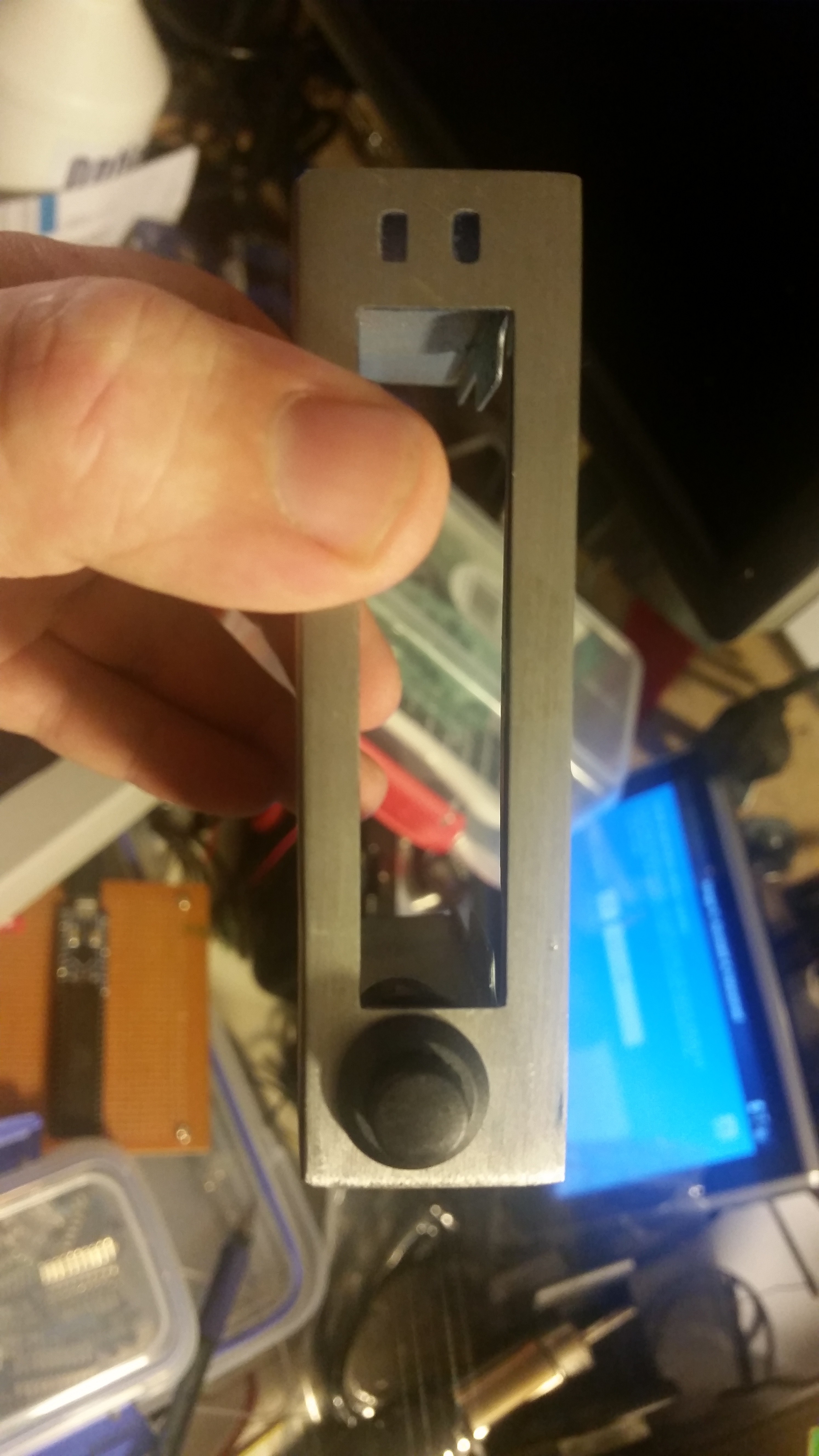
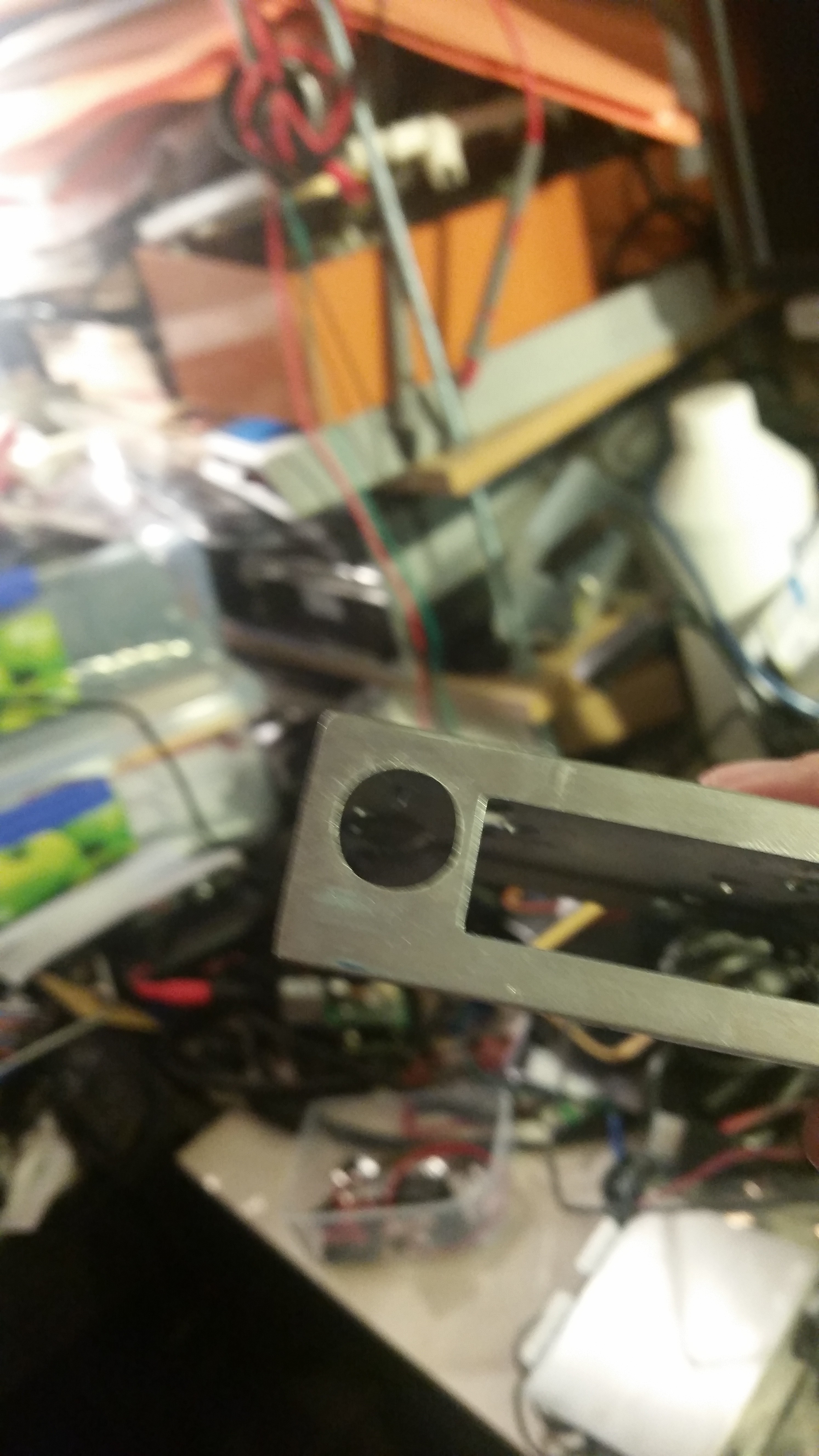
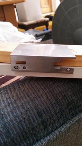
The original case had a nice square slot at the front right, which is perfect placement for a switch of some kind. However, I didn't want to trash the original ethernet switch in case I decide to use it later in another project. So looking through the box of switches I came across a black momentary closed push button . Only problem was that it has a circular diameter of 12mm - not a rectacular 8mmx3mm slot.
Opening up a square hole to a round hole isn't too much of a problem with the right drills and some cutting fluid. I used a 10mm drill to expand the hole, expecting to further open it up with a 12mm drill. Only problem, I had no 12mm... So a combination of a number of flat and curved files produced the below result. Not too bad, and covered by the bezel built into the switch.![]()
![]()
-
Sanding the Branding Away
12/13/2016 at 05:57 • 0 commentsSo the old 'Network Blue' of the case had been scratched and marked quite badly. The decision was made to return to bare metal. A Rotary Sander with 180 grit paper was applied to all surfaces for as long as it bloody took to get the old paint off. The clena surface was wiped down with mineral turpentine to clean off any paint dust and oil marks and then a single coat of clear varnish was applied. A single coat still allows a small amount of moisture/oxygen through, meaning the surface will age over time to gain an interesting 'attitude' to the machine's surface.
![]()
-
Case Hacking part 2
12/13/2016 at 04:27 • 0 commentsA relatively simple mod, given the placement of the cuts to be made. Angle grinder with metal blades cut two straight lines. Table was snapped off with pliers, then sanded. Once again, the slot is slightly over sized. Cut on the inside of the lines peeps. Excess can always be filed away later... Light filing to clean-up.
![]()
-
Case hacking part 1.
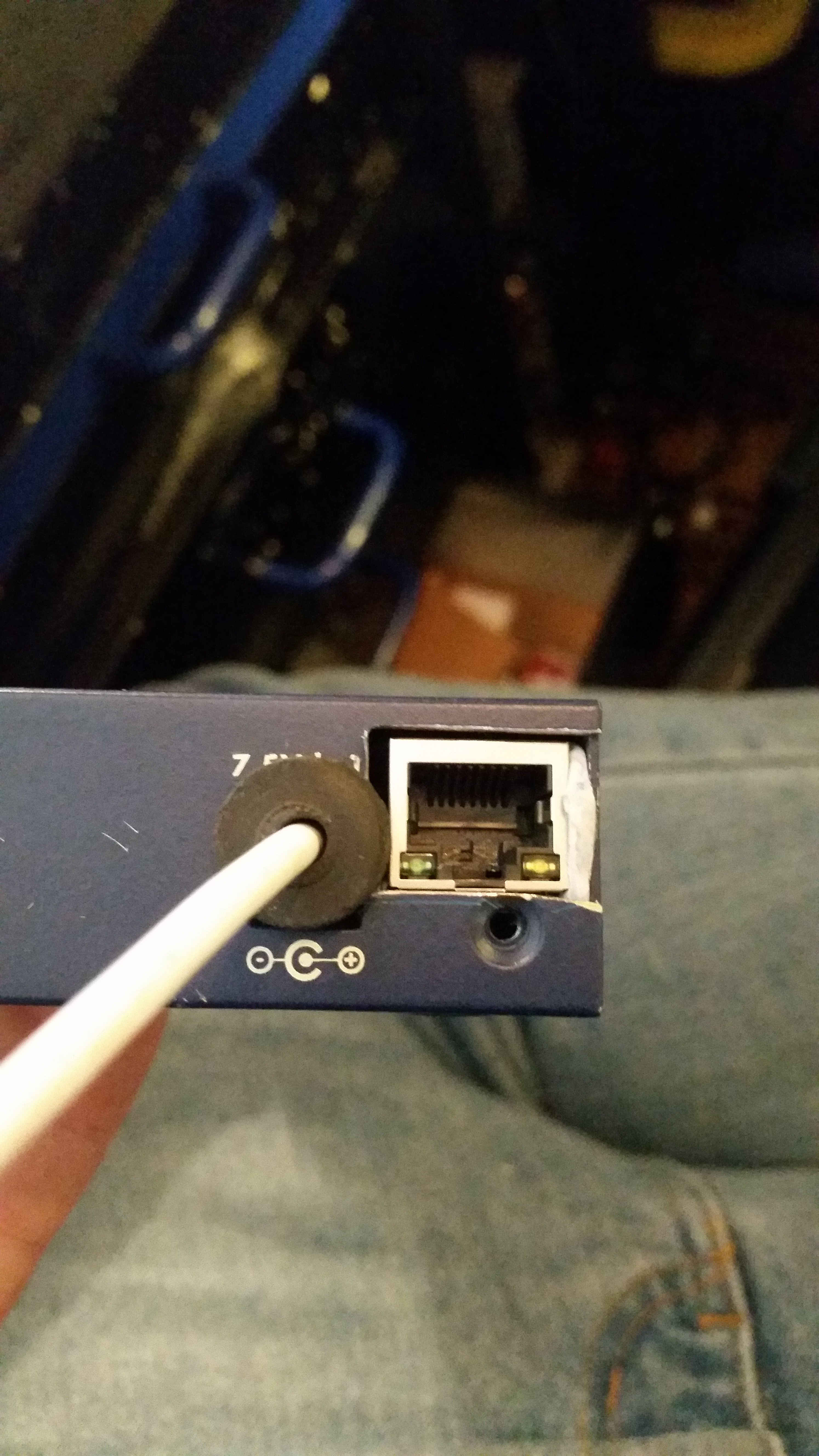
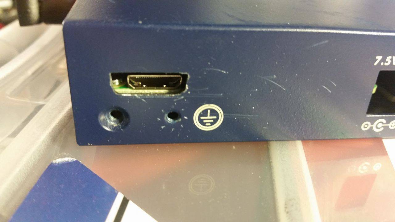
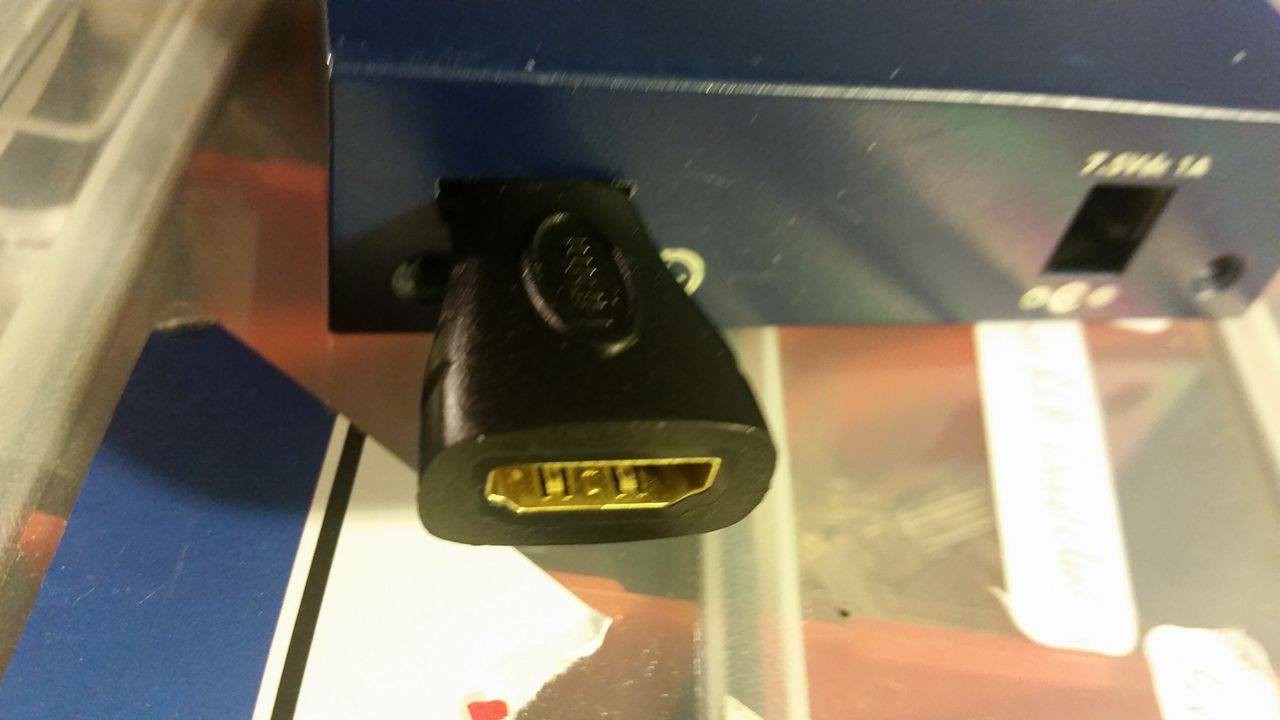
12/13/2016 at 04:12 • 0 commentsSo the first part of the case mod was to make the HDMI port accessible. I'm pretty disappointed with the result as i failed to follow the old 'measure once, cut twice rule. A series of 4 holes were drilled with a 1/8th drill, then filed into the shape of the port. One hole was placed to far to the left, and another drifted down the case, leaving an opening slightly to big. The micro HDMI to HDMI adapter covers most of the hole, but some form of repair may be needed at a later point.
![]()
![]()
-
Laying it out
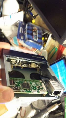
12/13/2016 at 03:41 • 0 commentsSo after deciding that I was going to build a mini pc in this case, the next task was deciding how it was going to fit together. Looking at the case, the large window at the front seemed to be perfect to access the 3 usb ports. Only the hdmi port on the pi zero needed to be accessible, so the pi zero was mounted to the rear and the ethernet port placed next to the pi zero. The original intention was to use the square slot that the power jack sat in for the ethernet port, but the pi zero and the module couldn't fit together. As it is an all metal case, having an internal wifi dongle would not work. Provision was made for a wifi dongle with an external dongle was made on the LHS of the case.
Four mounting points for each of the pi zero and the zero4u hub were marked out and made using a 1/8th drill. As the standoffs and screws used are m2.5, this allows approx 0.4mm on each side of the screw to provide a bit of wiggle room.
![]()
-
The beginning
12/12/2016 at 04:15 • 0 commentsSo I picked up this up this hub at the local tip shop. Fully functioning, but terribly out of date. Lives in a cute 1/2u high case. I've already removed the board and have put it aside for another project.
![]()
Pi Zero PC by Bay Networks (The Pikelet)
I acquired a great little EN104 Bay Networks 'Netgear Hub'. I decided to re-purpose it to house a little Pi Zer0.