Close
0%
0%

Unlock a Comcast XR16 remote control

x

Similar projects worth following

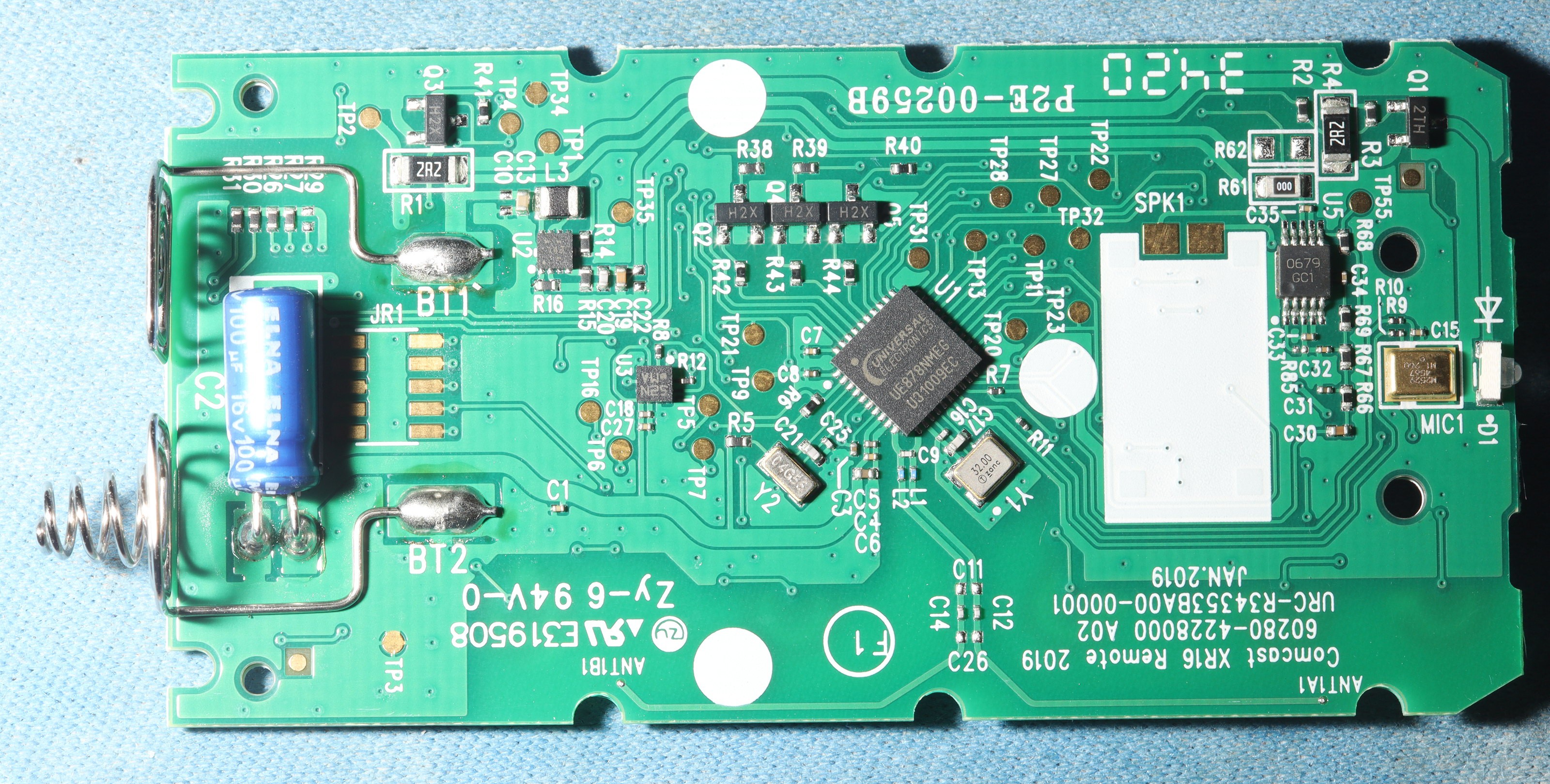
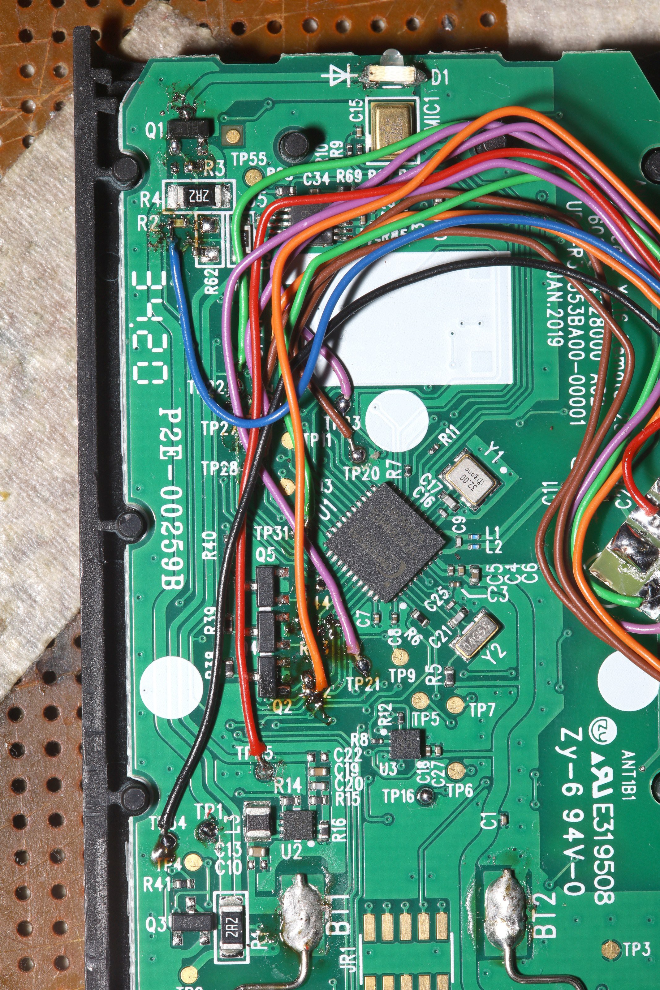
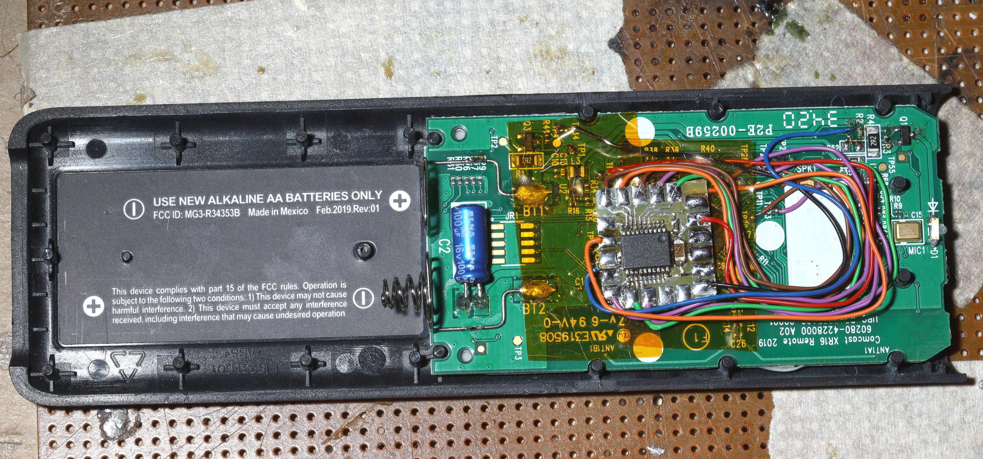
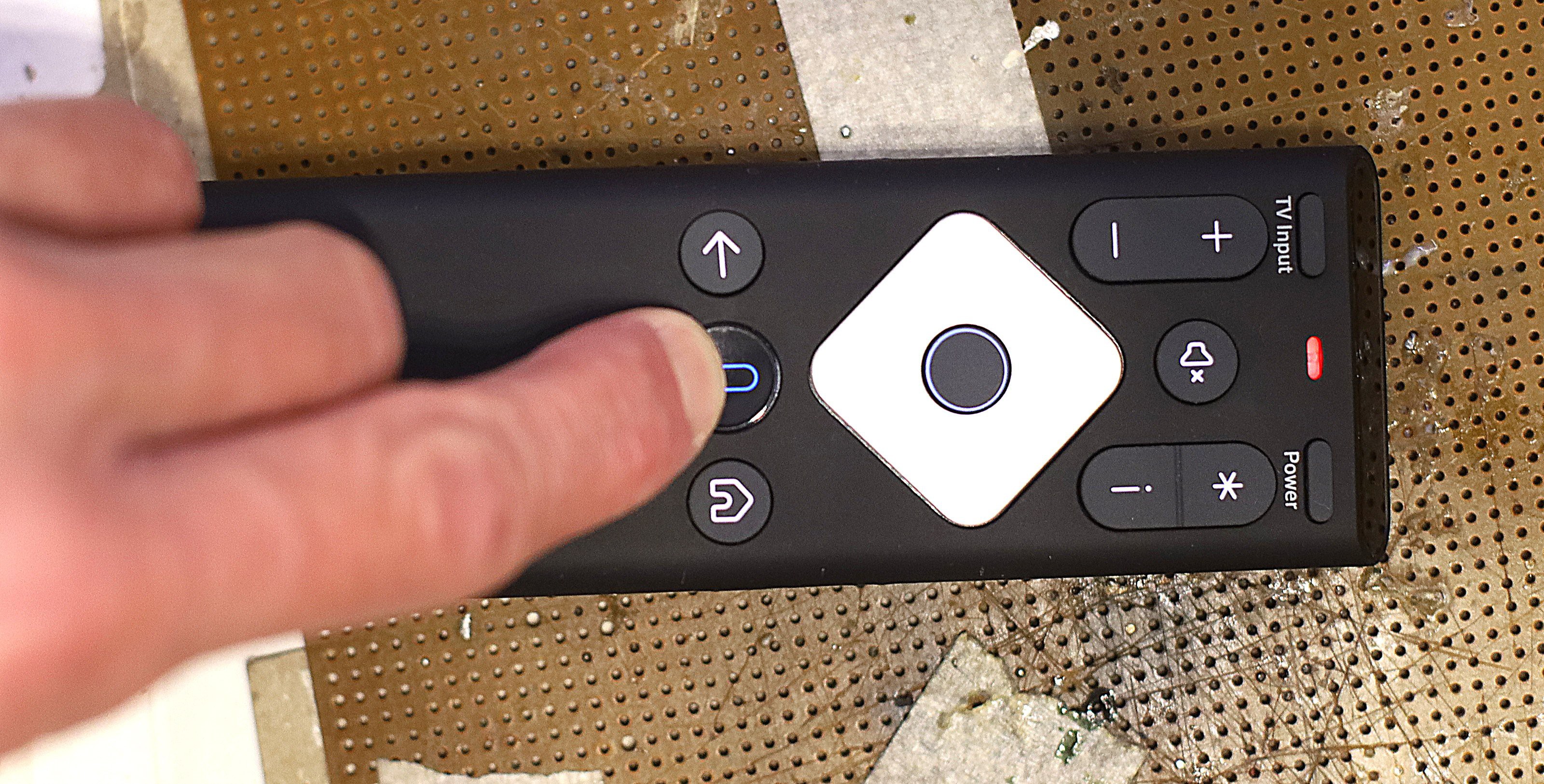
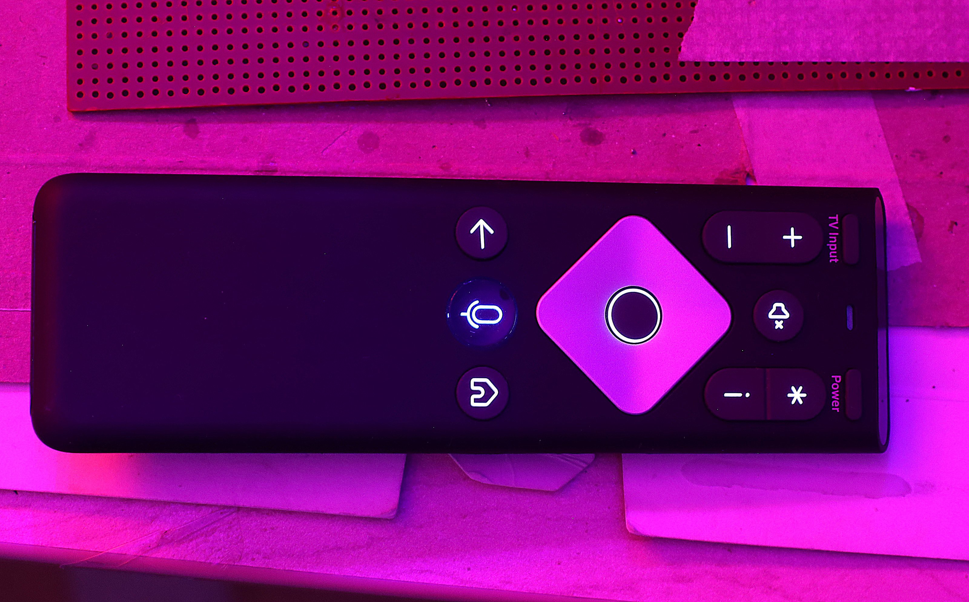
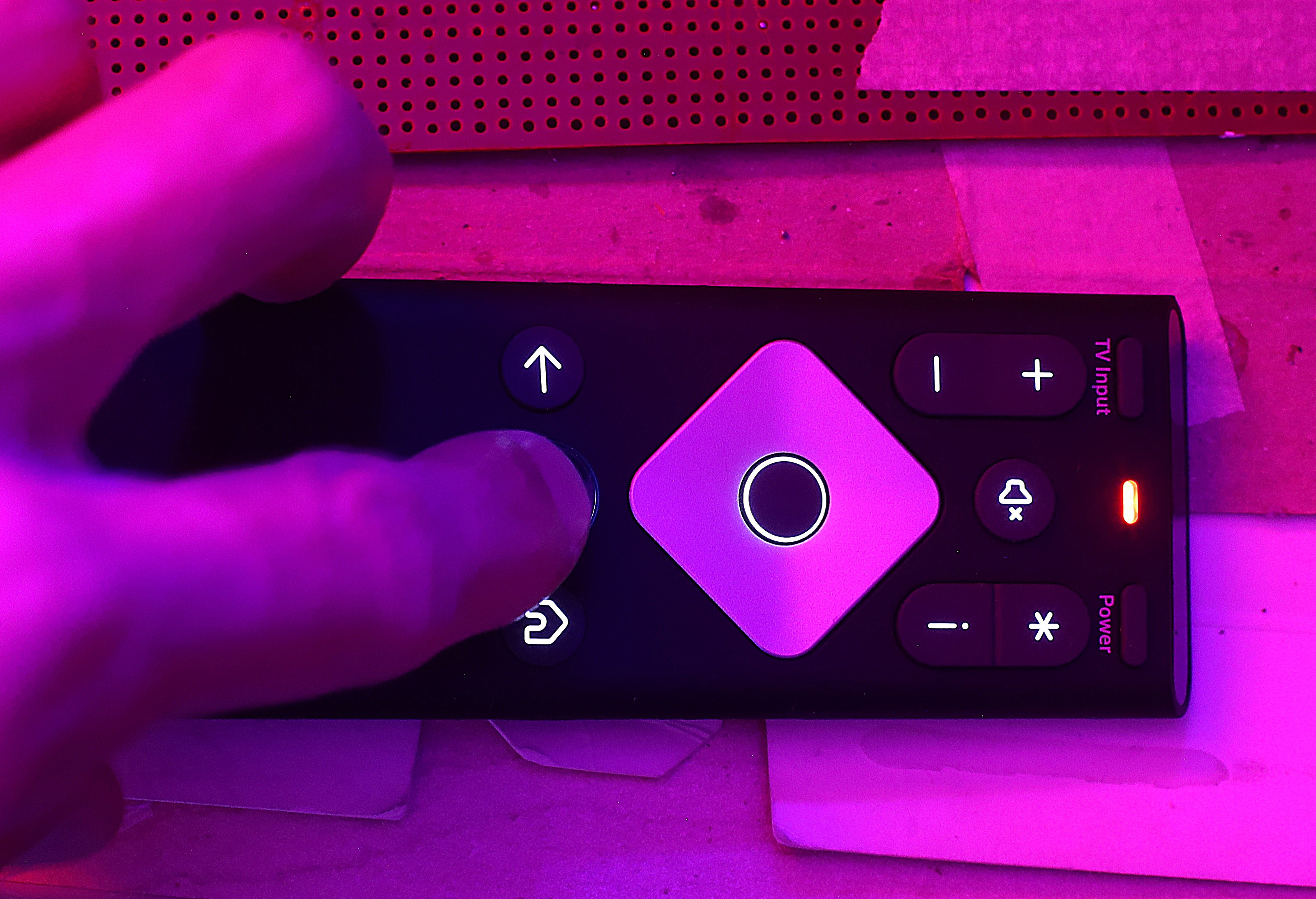
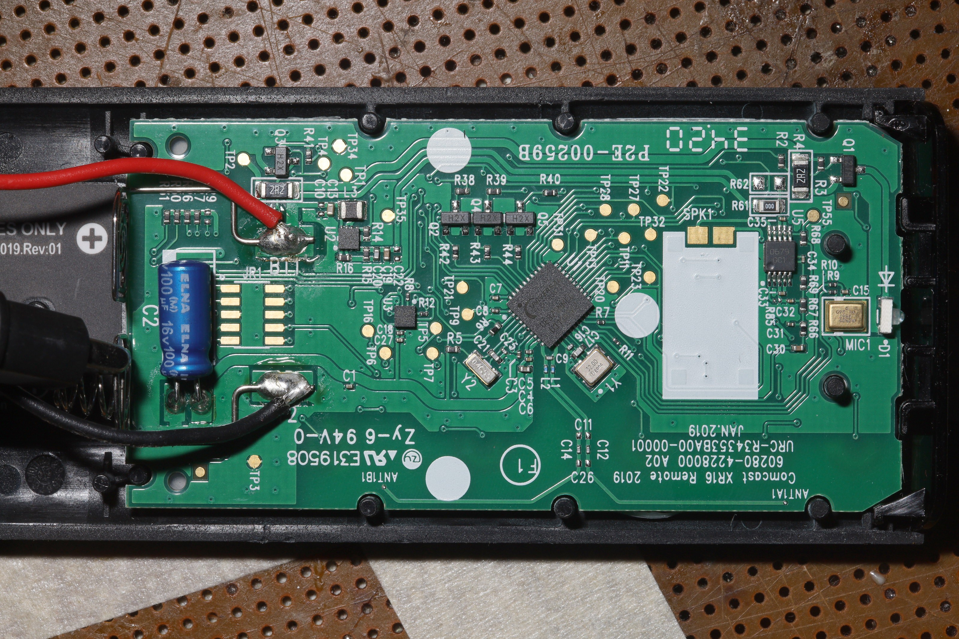
These are based on a smart remote brain: the UE878, require an 802.15.4 MAC to work at all, but expose all the signals required to detect the button presses & transmit IR for a simple 1 off user interface.  The enclosure is a lot nicer than a multifunction remote.  The buttons have backlights.  The plastic is soft.

The comca$t remote would serve the camera tracker & rep counter using basic IR.  It would not have the full smart functionality unlocked.

  • Board

    lion mclionhead01/14/2023 at 22:15 0 comments

    The atmega328 once again lost to the PIC16F1508 since there's no way 32 pins are going to take less space than 20 pins.  Due to lack of space, the servo controller for the camera head would be the IR receiver for the rep counter.  Usage for rep counting would depend on unplugging the servos while the thing would always run on the USB port.

    The trick was detecting the button matrix edges.  There's no guarantee a column edge TP27, TP28, TP31, TP32 would happen in the same clockcycle as a row edge TP20, TP21, TP22, TP23.  Fortunately, we know the rows are always high if inactive while only the columns go low if inactive.  Only the columns require detecting a falling edge.  A DC voltage is enough to detect an active row.

    In the interest of supporting the crummiest receivers, the IR protocol would be 500us pulses, 500us between pulses for a 0, 1500us between pulses for a 1.  32 bit start code.  5ms pulse every 100ms for a repeat.

    Strangely, PWM4 couldn't drive PNP transistor Q1.  It would successfully pull the base low for 300us, then switch back to input mode on its own.  It didn't matter if it was PWM or DC.  It was failing down to 3mA of current sinking.  This was traced to an improperly set duty cycle of 5%.  The duty cycle had to be 50% for it to drive the transistor.

    Noted the green LED doesn't relight for some time after the button is released even though every button press transmits.  It's forcing the red LED to stay on for a certain time to indicate an error.  The decision was made to connect the red LED to the PIC & disconnect all the other LEDs so every button press would light red every time.

    The last problem was an intermittent glitch from I to right arrow.  The problem happened if I was held down.  1 solution is never to press I.  Another idea is to reject the next button press without a timeout.  

    LED hookups to Q2 & Q1.

    Buttoned up for enclosure.

    Hard won, traditional red LED.

    Snazzy button LEDs.  There are universal remote controls with similar lighting, but they're ugly, bulky & aren't as fast at replaying codes as the custom programmed PIC.  Some design effort went into the commie.

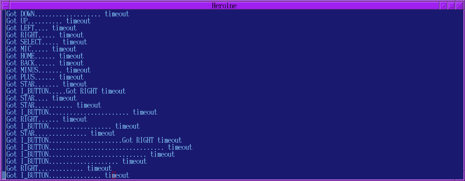
    Receiver test program.
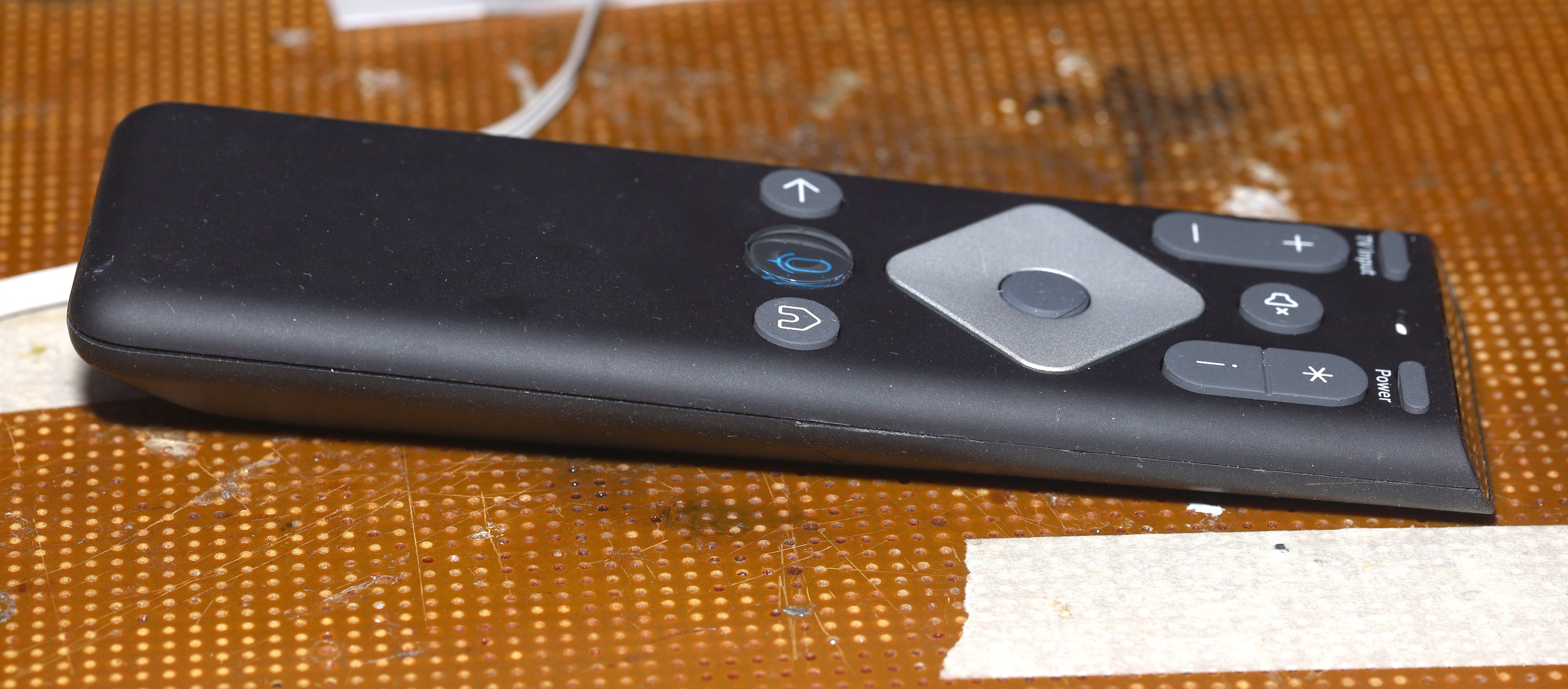
    The case is a bit chewed up from many openings.  It relies on friction instead of farsteners, but fortunately doesn't use broken tabs.

  • Probed signals

    lion mclionhead01/14/2023 at 09:32 0 comments

    TP1 - battery +

    TP2 - battery +

    TP3 - GND

    TP4 - battery +

    TP16 - momentary battery +

    TP20 - pulse GND if back, left, TV input, *

    TP21 - pulse GND if MIC, select, -, power

    TP22 - pulse GND if home, right, +, i

    TP23 - pulse GND if down, up, mute

    TP27 - battery+/pulse GND if up, *, i, -

    TP28 - battery+/pulse GND if back, MIC, home

    TP31 - battery+/pulse GND if left, right, select, down

    TP32 - battery+/pulse GND if TV input, power, +, mute

    TP35 - 3.3V  This turns on as soon as a button is pressed but stays on for several seconds after the button is released.

    TP20, 21, 22, 23 are always battery+

    TP27, 28, 31, 32 are battery+ & pulse GND only when their group is pressed

    GND pulses are 30us long, repeating every 25ms

    Power & MIC suck 40mA.  The rest suck 20 - 30mA.  The existing brain can stay around just to manage power & backlighting.  It blinks error codes & sucks amps but back lighting looks better than nothing.

    Q1 is a P transistor which feeds the LED battery +.

    Q5 lights a blue LED when the mic button is pressed.

    Q4 lights a green LED when any other button is pressed.

    Q2 flashes a red LED to signify an error after every button press.  That could be disconnected.

    11 signals in total would be required.  The buttons require 8 signals.  Then there's 3.3V, GND, & LED.

    There's room for a 27x24x5mm board.  A bunch of standoffs press the board against the buttons.  Former space for the speaker can be used for excess wire.

View all 2 project logs

Enjoy this project?

Share

Discussions

Similar Projects

Does this project spark your interest?

Become a member to follow this project and never miss any updates