 Savo
SavoIn addition to this being my first power-conscious project, it would also be my first foray into PCB artwork. Luckily I wouldn't need to make the art myself, my sister handled that.
Schematic Design
As mention in my first project log, the circuit is pretty simple, other than a handful of passives and LEDs it's really just an ATtiny85. When I started making the board I considered using an ATtiny1617 since I also had a few of those around and they had hardware peripherals for capacitive sensing as opposed to the hack that allowed the ATtiny85 to work. I believed that it could squeeze even more life out of the batteries, although I never tested this since the ATtiny85s performed just fine.
 Schematic for the raccoons
Board Design
I am not an artist, luckily I was able to enlist the help of my sister to make me the artwork I was looking for. I gave her these requirements:
- Cannot exceed 100mm x 100mm
- Limited to the palette available for my PCBs, based on the PCB production limitations.
- Lighter black (copper fill under solder mask)
- White (silkscreen)
- Silver (solder on exposed copper/gold)
- Gold (plated copper)
- Black (solder mask over no copper)
- The tummy needed to be filled with copper.
- Need a specified outline
With these she produced the following image for me to use. Originally a vector image then I converted it to a bit-map.
 The base image, with a green outline for the edge cut.
The reason I originally had her prepare it as a vector image was to make use of Gerbolyze for putting the art in place. However the problem with Gerbolyze I found was that it is meant for non-functional art, which means it will maintain a clearance around any functional parts of the system, not acceptable for me since I wanted the raccoon’s stomach to be connected as a capacitive sensing pad.
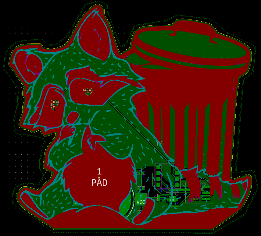
So I moved to using KiCad’s built-in bit-map to component utility. This allowed me to convert individual PNG files into the polygons and use them in any layer, e.g. “top silk screen” or “bottom solder mask”. To use it I broke down the art into the layers each feature needed to be on.


With them all converted, I got the following render of the board. Looked sweet! Note that in KiCad I couldn’t selectively set the pads that would be coated in solder so they would render silver alongside the gold, hence why it is all gold.

Look, it has a little belly button!
Functional Layout
With the art in place I had to do a bit of routing for the electrically functional parts. Since I wanted the art undisturbed (except for the eye LEDs), I had to try my best to do all the routing on the back that I could. I was successful in this thanks to some very windy traces, vias are used to deliver power to the eyes with them emerging at the LED pads where the LED will cover them.
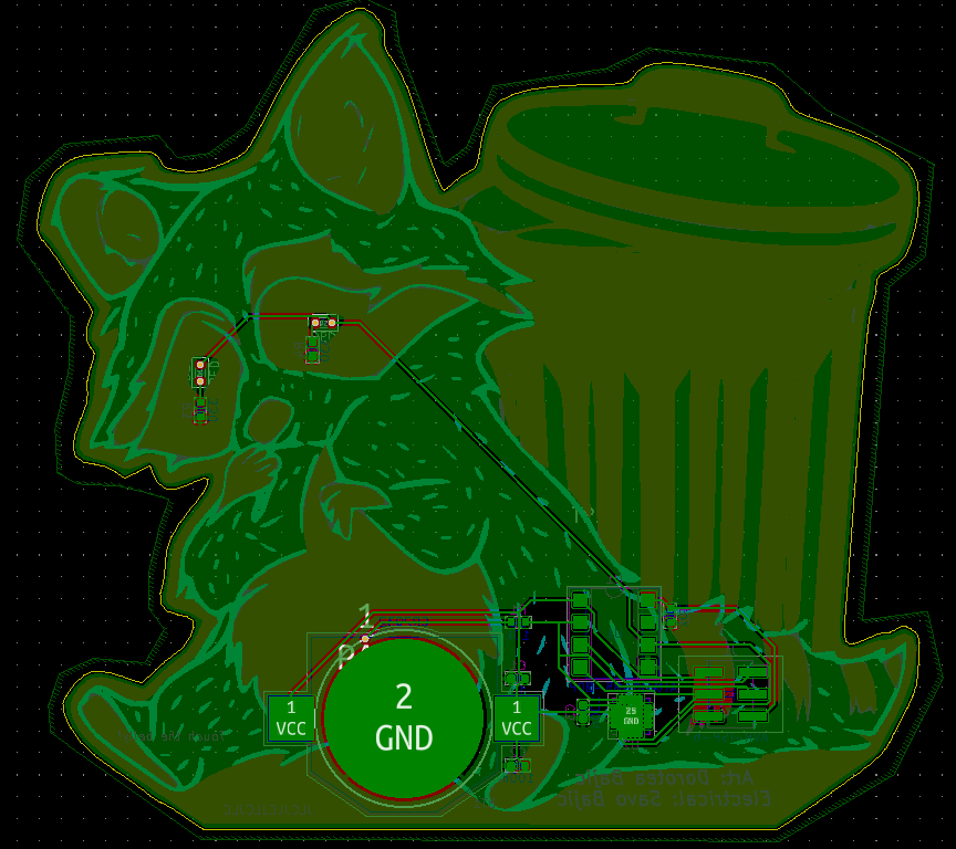
The uninterrupted front view
Discussions
Become a Hackaday.io Member
Create an account to leave a comment. Already have an account? Log In.