 Jarich
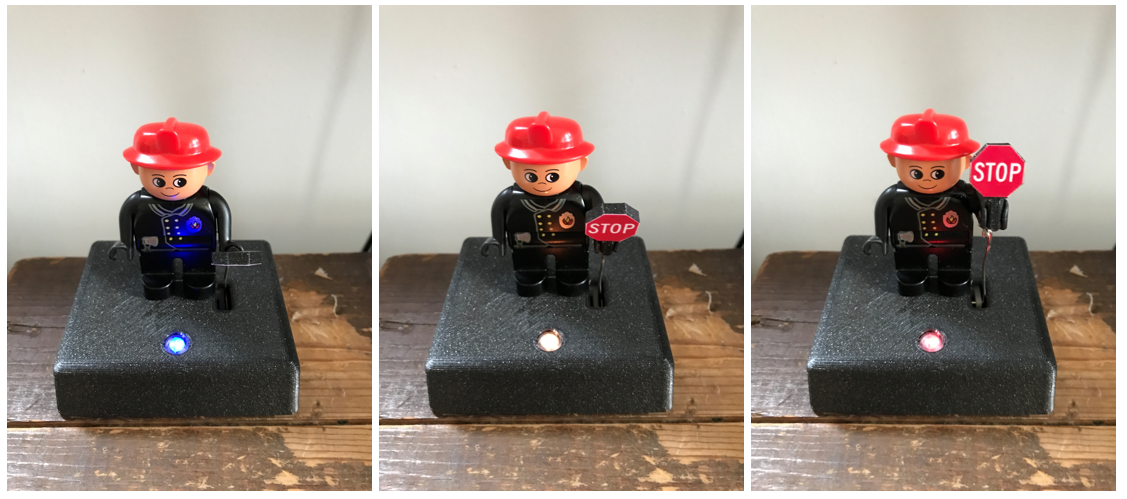
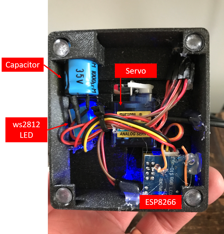
- ESP01 module (ESP8266) attached to a ESP01 LED shield
- A neopixel (ws2812) LED connected to the GPIO2 of the ESP module
- A small servo (S0006/MG996) connected to the GPIO0 of the ESP module
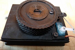
- Capacitor; maybe not really necessary. I took the biggest one that still fitted in the base
- 3D printed base and stop sign
- Duplo fire fighter figure :-)
The system is powered by a USB cable (5v). The ESP shield, servo, LED, and capacitor are directly connected to the 5V and GND of the power cable. the servo and LED have connection to GPIO pins of the ESP module
I used an EPS01 module which has 4 exposed GPIO pins. In principle any board with an esp8266 or ESP32 chip can be used, but not all GPIO pins are suitable.
The ESP01 module was attached to a ESP shield with build-in 5V->3.3V regulator and connector for ws2812 LED strips. Not needed if you use other ESP-based boards with build-in voltage regulators and exposed GPIO pins.
the signal/data cable of the servo I soldered to the GPIO0 connection of the shield.
The servo is attached to the hand of the Duplo figure by using a thin metal wire such that the arm can be raised and lowered with the servo.
Be aware that the servo draws quiet some current (>0.5A at 5V) when making sudden moves or not being able to move to it's desired state. I noticed that the ESP can get unstable (rebooting) or die when this happens. I added a chunky capacitor to smooth out current peaks; and in the ESPHOME configuration YAML file I defined that the servo should not move too quickly and detach the servo as soon as it reached it's desired position.
Software:
I flashed the ESP module using the ESPHOME integration.
I configured the servo and LED by using the code below.
(google: ESPHOME+Servo and ESPHOME+ws28212+neopixel)
[add the following code below your default ESPHOME configuration...]

number:
  - platform: template
    name: Servo Control
    min_value: -70
    max_value: 60
    step: 1
    optimistic: True
    set_action:
      then:
        - servo.write:
            id: my_servo
            level: !lambda 'return x / 100.0;'

servo:
  - id: my_servo
    output: pwm_output
    auto_detach_time: 0.1s
    transition_length: 2s

# Example output platform
# On ESP32, use ledc output
output:
  - platform: esp8266_pwm
    id: pwm_output
    pin: 0
    frequency: 50 Hz

light:
  - platform: neopixelbus
    type: GRB
    variant: WS2812
    pin: 2
    num_leds: 1
    name: "NeoPixel Light"
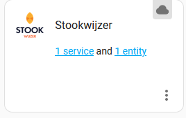
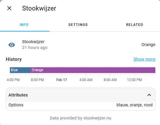
I added the Stookwijzer integration to my HomeAssistant instance:
In the same way the ESPHOME integration allows to control the servo and LED based on the configuration above.
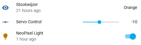
I use a simple automation in HomeAssistant to move the servo to a certain position and set the LED to a certain color and brightness based on the Stookwijzer advice.
I designed the 3D printable case in OnShape and printed it on my Prusa mini 3D printer.
Hot glue is very helful in assembling everything :-).
 theschlem
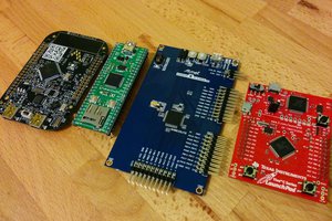
 Mike Szczys
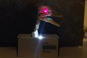
 MaBe42
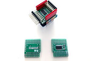
 deʃhipu