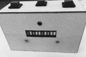
• 1
    Print Housing

    The housing needs to be 3D printed. The bottom piece does not need supports. The top piece should have supports for the holes where the pegs in the bottom piece slide in. Play with the support settings in the slicer (I used Cura), so that you have you have enough room on the X/Y axis to remove them from the holes. I used 20% infill and three perimeter walls. Your mileage may vary. You may want to use horizontal expansion for the holes on the top piece so the pegs on the bottom slide in.

  • 2
    Assemble and Paint Housing

    The pegs in the bottom piece should slide into the holes on the top piece. If they don't, take a drill bit and widen the holes a bit. The pegs should be snug. I also used glue to keep the two parts together, though this may not be necessary.

    To make the housing appear smooth, I used wood filler to fill the seam between the top and bottom pieces. I then sanded the pieces to smooth them.


    After sanding, I primed the housing with automotive primer-filler and re-sanded the housing. Finally, I painted it.

  • 3
    Solder the components on to PCB

    This step is fairly explanatory. The only difficult part was soldering the WS2812B-2020 LEDs. For that step, I used solder paste and a hot air gun. An oven would have been easier, but I didn't have one. The through hole components were soldered with flux and normal leaded solder.