If you have hard-time 3d printing stuff and other materials which i have provided in this project please refer the professionals for the help, JLCPCB is one of the best company from shenzhen china they provide, PCB manufacturing, PCBA and 3D printing services to people in need, they provide good quality products in all sectors
Please use the following link to register an account in JLCPCB
Pcb Manufacturing
----------
2 layers
4 layers
6 layers
PCBA Services
JLCPCB have 350k+ Components In-stock. You don’t have to worry about parts sourcing, this helps you to save time and hassle, also keeps your costs down.
Moreover, you can pre-order parts and hold the inventory at JLCPCB, giving you peace-of-mind that you won't run into any last minute part shortages. jlcpcb.com/RNA
3d printing
-------------------
SLA -- MJF --SLM -- FDM -- & SLS. easy order and fast shipping makes JLCPCB better companion among other manufactures try out JLCPCB 3D Printing servies
JLCPCB 3D Printing starts at $1 &Get $54 Coupons for new users
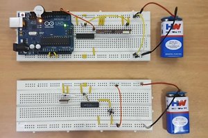
The Analog Joystick is similar to two potentiometers connected together, one for the vertical movement (Y-axis) and other for the horizontal movement (X-axis). The joystick also comes with a Select switch. It can be very handy for retro gaming, robot control or RC cars. So let's understand how it works!
_wWISwu2awC.png?auto=compress%2Cformat&w=740&h=555&fit=max)
The home position for the stick is at ( x,y:511,511). If the stick is moved on X axis from one end to the other, the X values will change from 0 to 1023 and similar thing happens when moved along the Y axis. On the same lines you can read position of the stick anywhere in upper half hemisphere from combination of these values.
The potentiometers act as voltage dividers. This module produces an output of around 2.5V from X and Y when it is in the resting position. Moving the joystick will cause the output to vary from 0v to 5V depending on its direction. If you connect this module to a microcontroller, you can expect to read a value of around 512 in its resting position (expect small variations due to tiny imprecisions of the springs and mechanism). When you move the joystick you should see the values change from 0 to 1023 depending on its position. The given example values are for a 5V microcontroller or a development board with 10bit ADC resolution like Arduino UNO or nano
The Joystick itself only contains the two potentiometers for each axis and a switch to register the click. One side of the potentiometers is connected to the ground and the other to the VCC. The center pins are connected to the VRx and VRy pins respectively. Similarly, the switch is connected between the GND and the SW pins. And in some modules, there is also an unpopulated space for a pull-up resistor on board for the switch.
If your Joystick module is not working properly the first and important step is to make sure all the connections are correct. Once the connections are verified, we can move forward to the next diagnosing step. If the reading from the VRx and VRy is not proper or it jumps around too much, then there must be a problem with the potentiometers. You can gently pop the potentiometers out of their default position by lifting them slightly. Give them a good clean using IPA or a similar cleaning solution and then pop them back in, to see if this has fixed the issue. If not either replace the potentiometer or the module itself.
The sketch starts by defining the connections to the Joystick module. The SW pin is connected to Arduino’s Pin A2 while the VRx and VRy pins are connected to Analog pins A0 and A1.
#define Xaxis_pin A0 // Arduino pin connected to the VRx Pin#define Yaxis_pin A1 // Arduino pin connected to the VRy Pin#define SW_pin A2 // Arduino pin connected to the SW Pin
In the setup() function, we initialized the SW pin as an input and keep it HIGH. This is as same as declaring the pin as INPUT_PULLUP. When the switch...
Read more »
 UTSOURCE
 Sander van de Bor
 adamc
adamc
That's another project just scrapped from the internet. Published to just advertise JLCPCB. And the code isn't even corect!