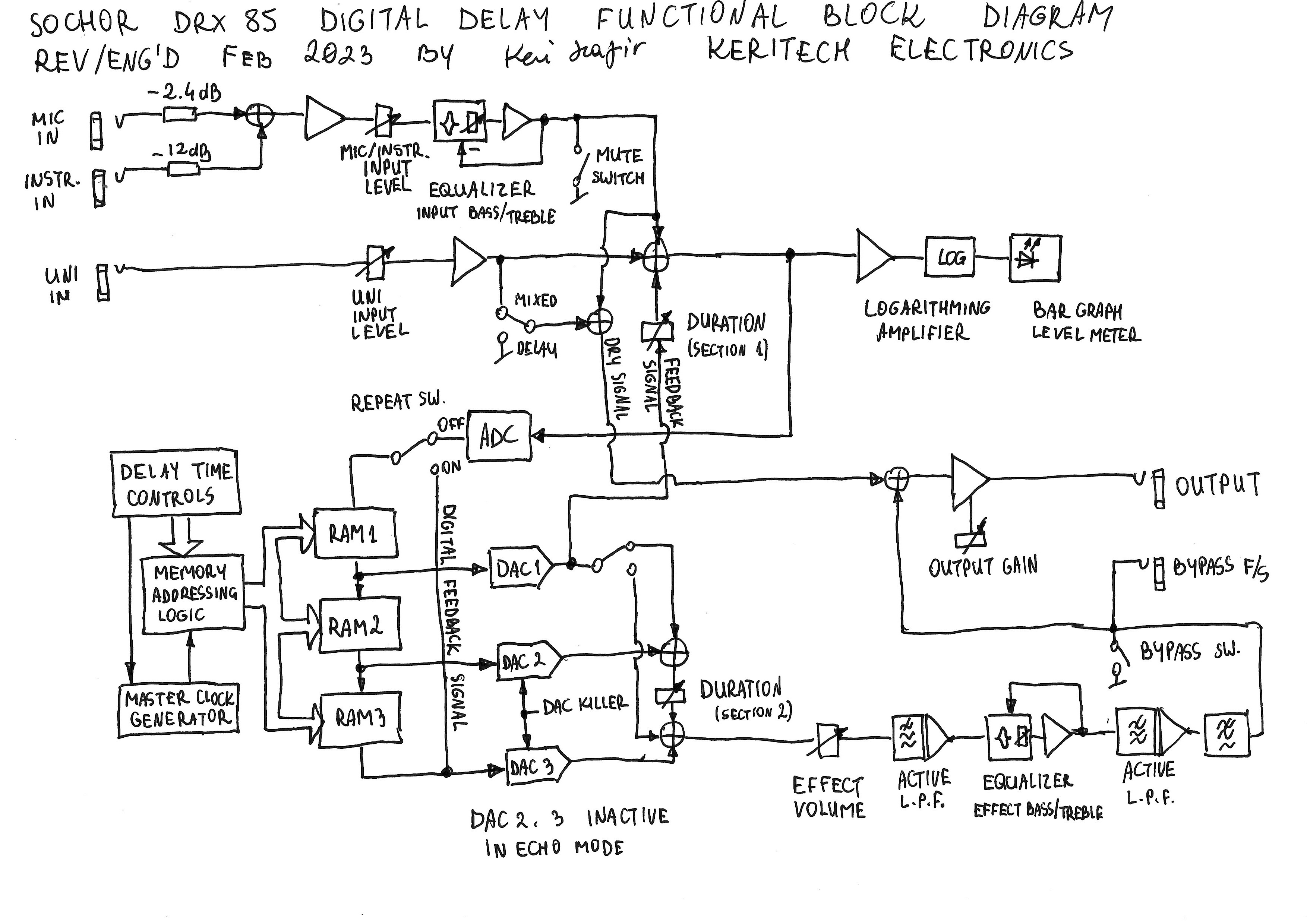
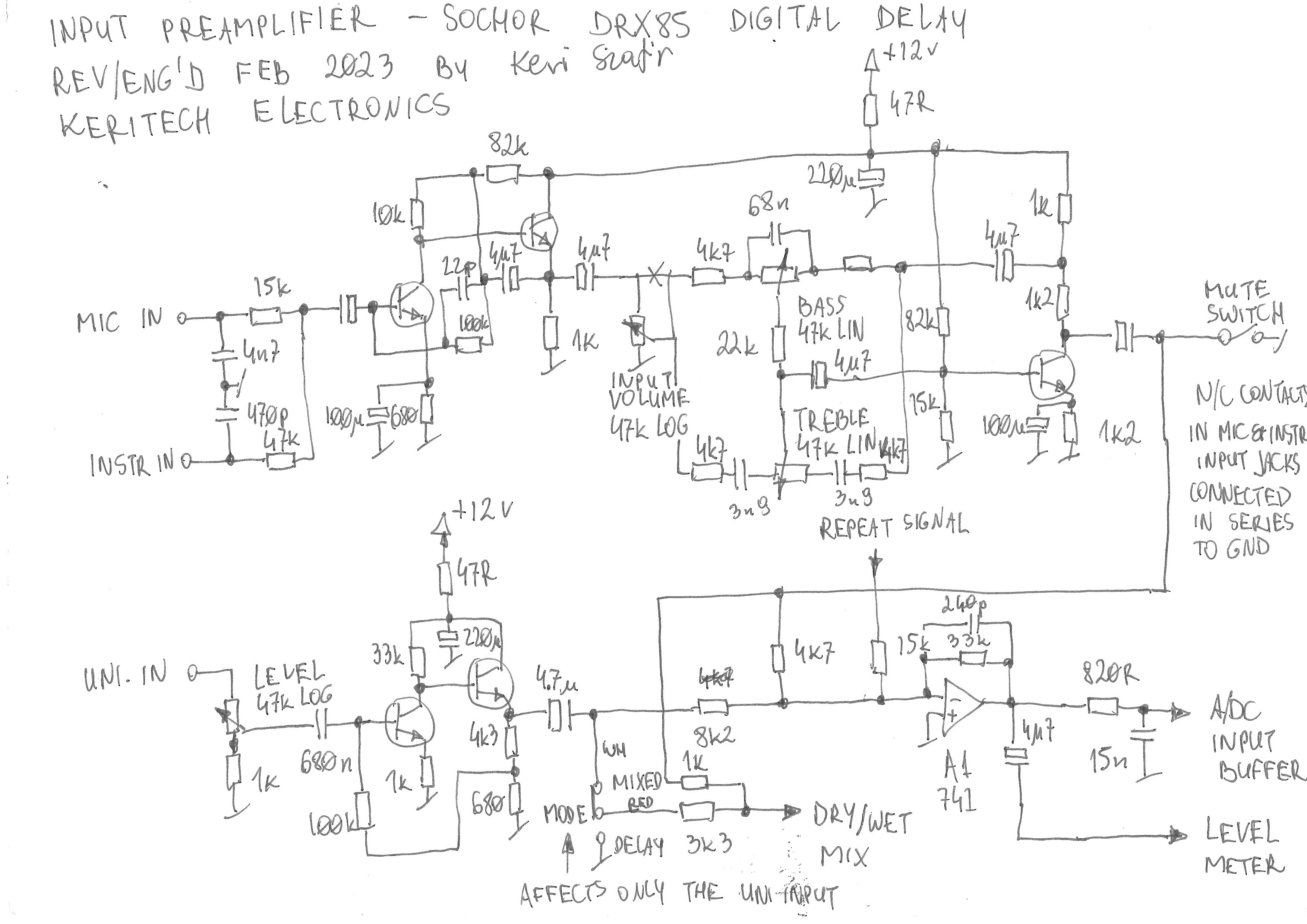
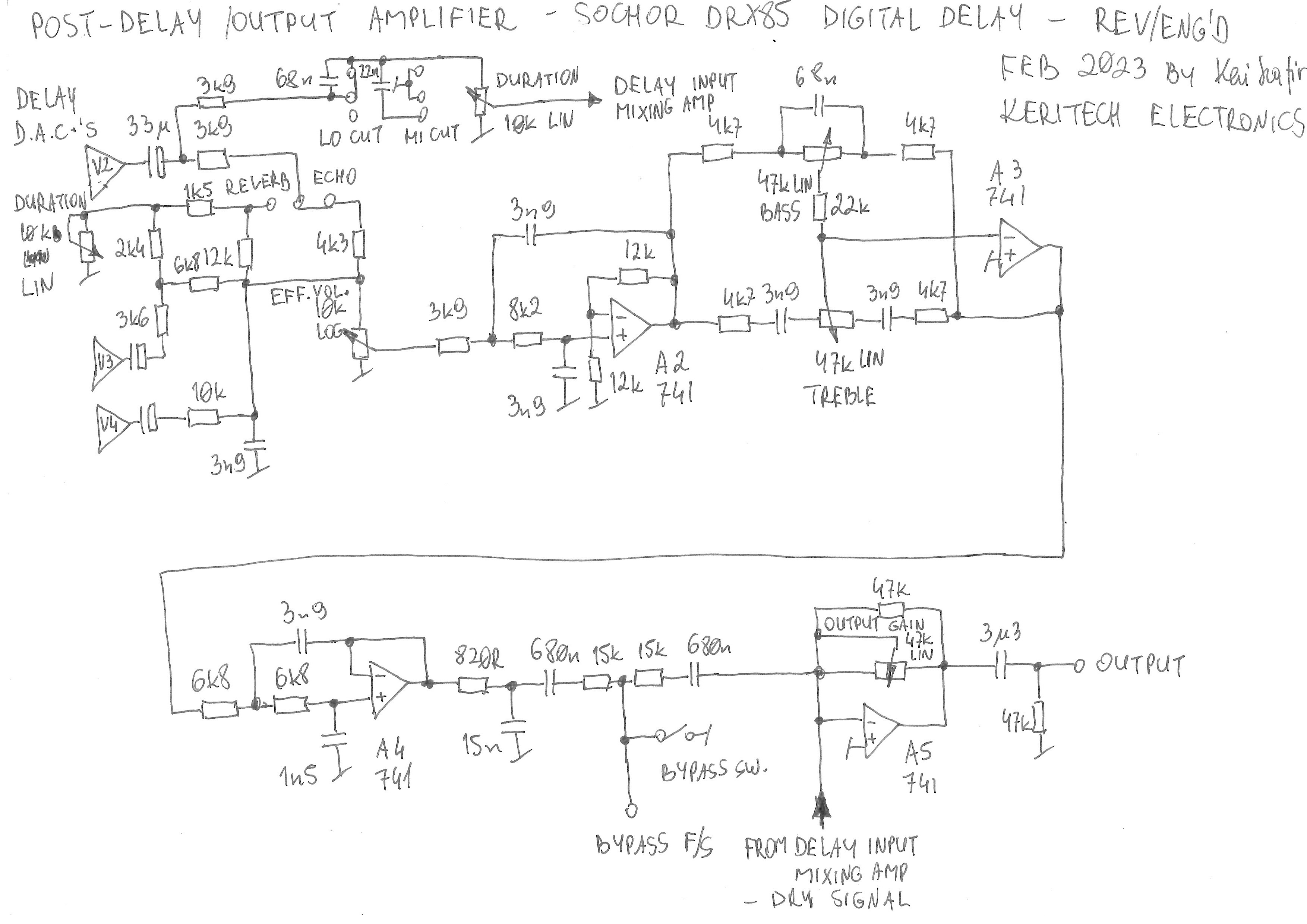
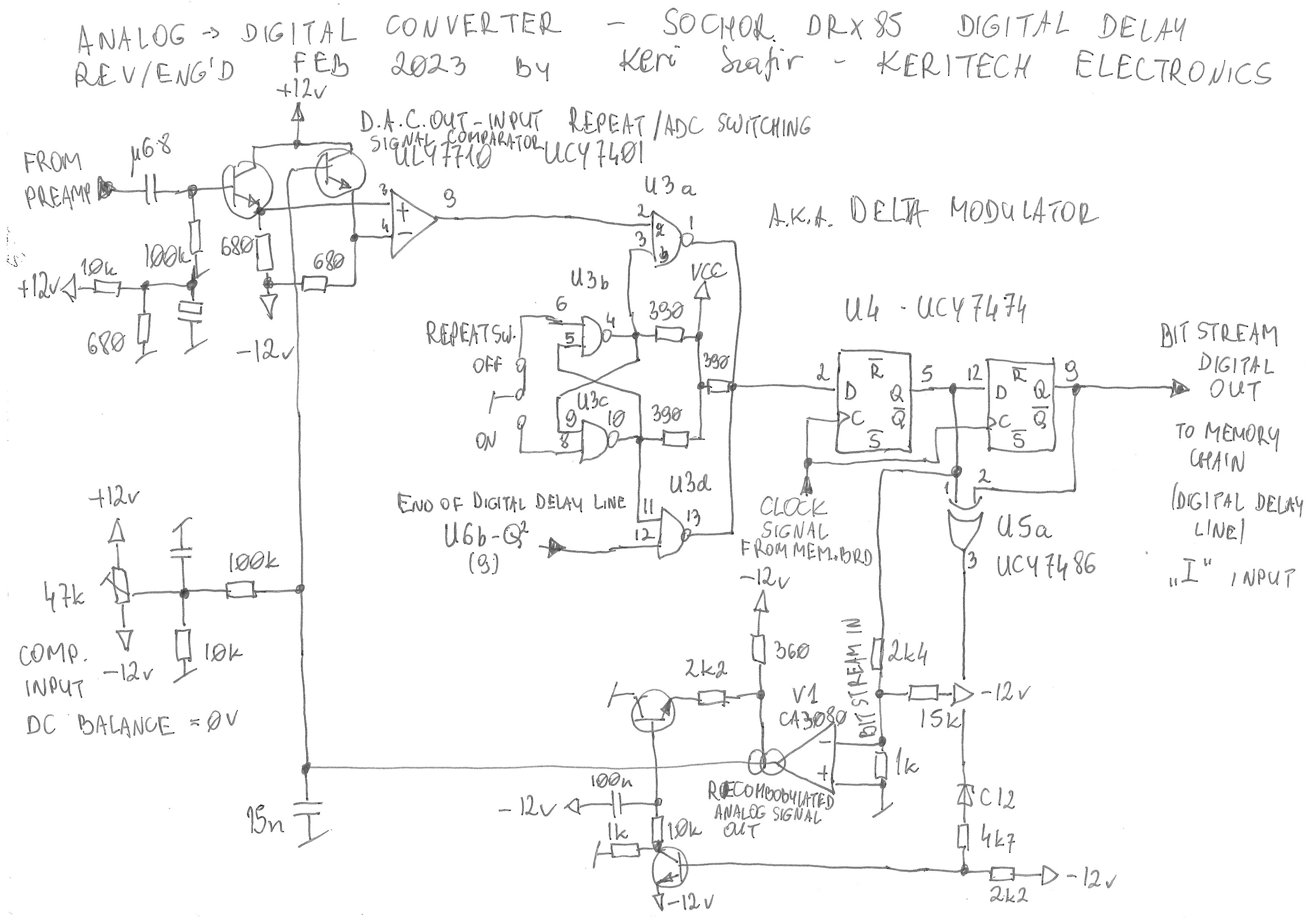
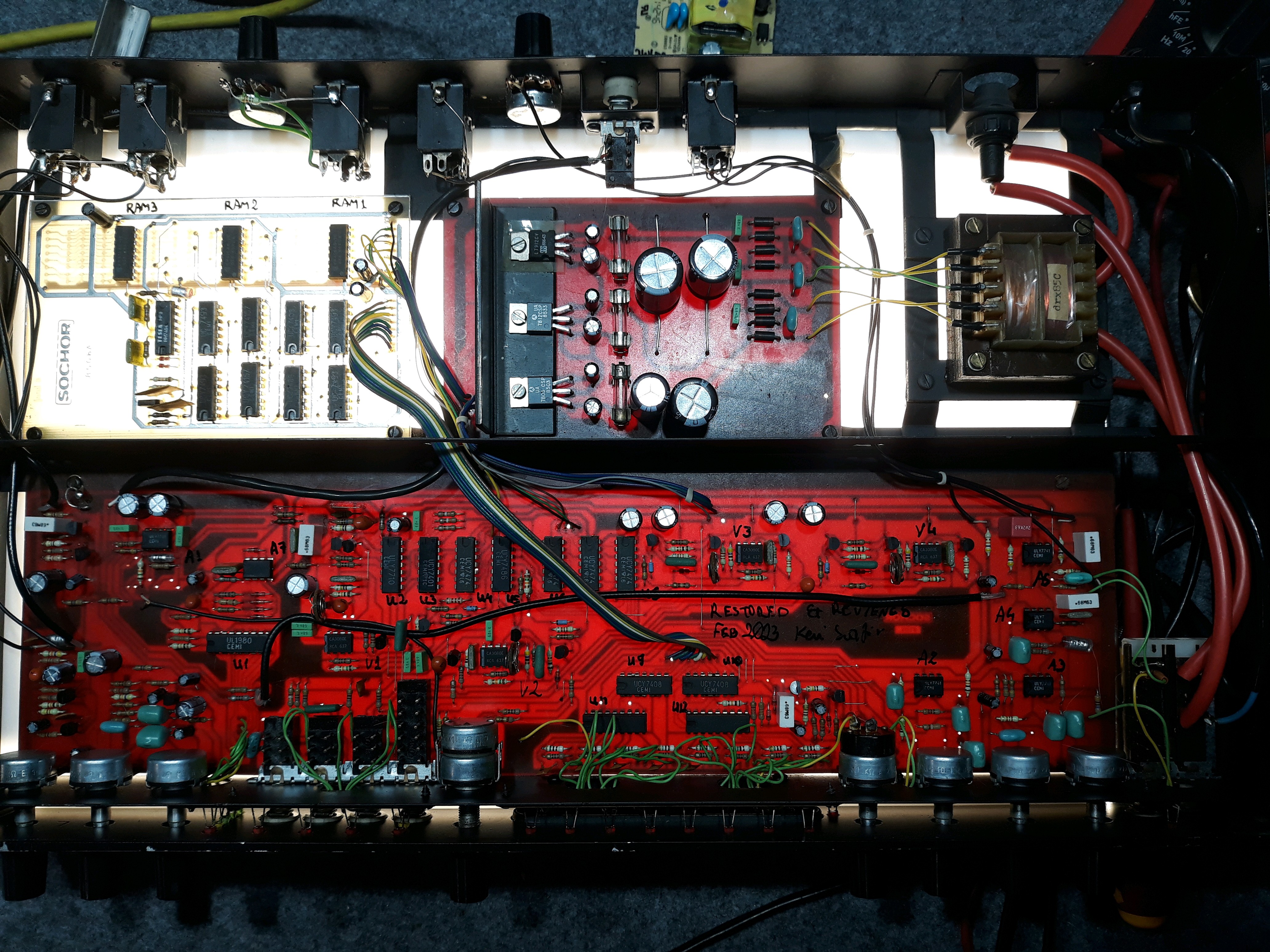
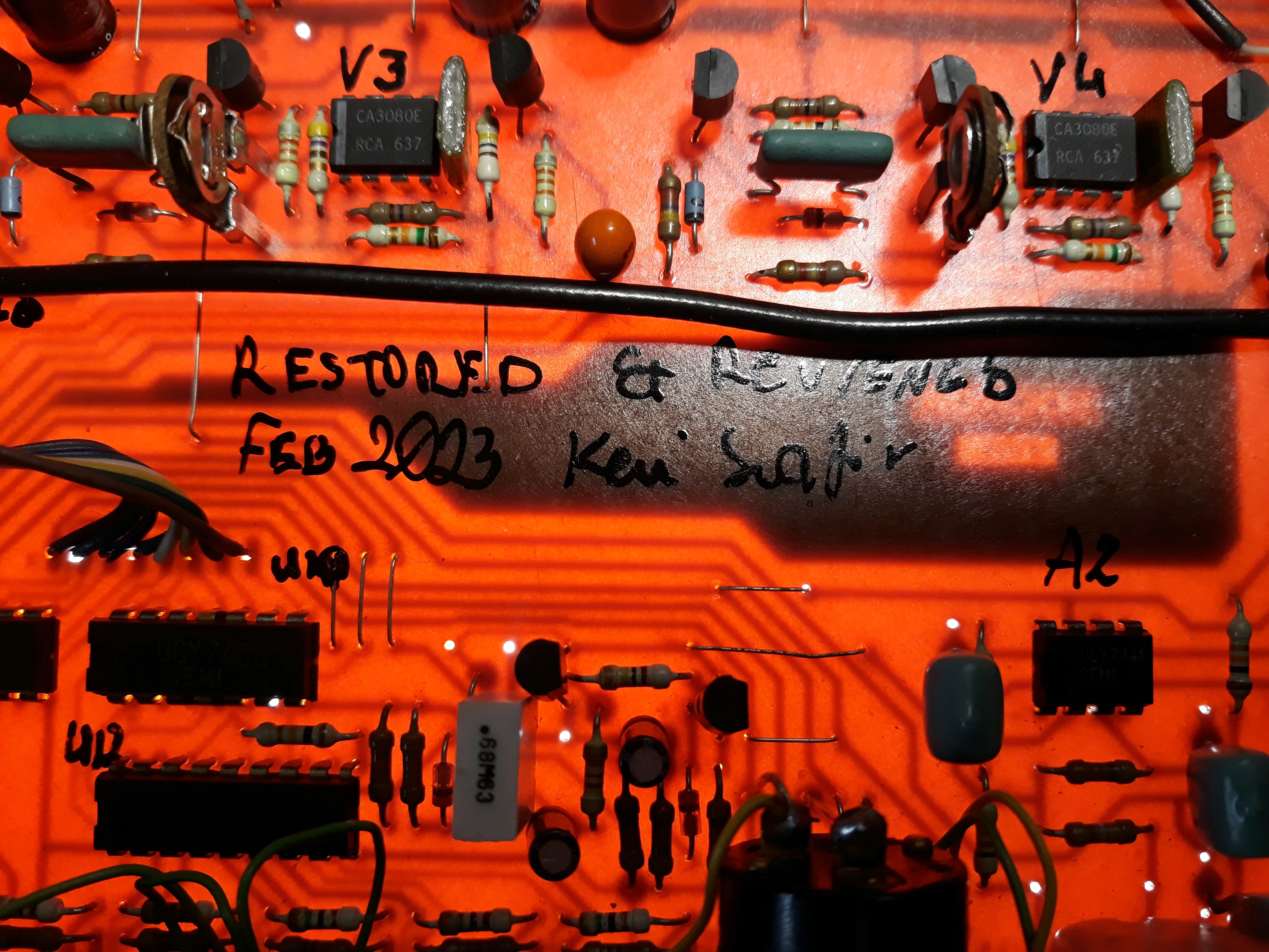
• Finally - schematics!

    Keri Szafir03/05/2023 at 19:19 0 comments

    The Sochor DRX85 is a complex device consisting of input and output preamplifiers, analog-to-digital and three digital-to-analog converters, mode/function selection switches and circuits, time circuits (haha), power supply, level meter and the most important part: the RAM chip based delay line where data is stored in a cell at a time, and then read from this cell after the delay time has passed. The device uses three 64kbit RAM chips, so it can store 192kbit of data at a delay time of up to 1280ms. The memory board was designed with more than just three chips in mind and works by daisy-chaining them, though I'm not sure if there was a version of the device that actually used more than three (the design minimum). There is no existing data or schematics on the web, apart from what I found out by reverse-engineering.

    First, let's take a look at the high-level design, block diagram:

    The mic and instrumental inputs pass through a preamp with volume and tone controls on the front panel, whereas the universal input with a level adjustment pot on the back has a feature the others don't: it can be delayed without mixing with the dry signal. Probably meant for effect send/return loops in mixers, where you can adjust the proportions between dry and wet on the mixer rather than on the effect device. The "bypass" switch doesn't bypass the effect - it just shorts the wet signal to ground, allowing dry only.

    It's interesting that the input preamplifier - apart from the stage feeding the meter and ADC buffer - is built entirely with discrete transistors rather than 741 opamps. It also tells volumes about the IC market in mid `80s here; no TL072, JRC4558 etc. lower noise chips. The tone controls are classic active Baxandall type.


    Post-delay circuit is mainly DAC mixing (where the 2nd and 3rd DAC which I marked V3 and V4 is active only in the "reverb" mode), two Sallen-Key type active low-pass filters, between which we can see an even more classic op-amp based active Baxandall tone controls. Then some passive LPF and a bypass switch and footswitch that shorts the wet signal to ground. Then the dry/wet mixing node and final opamp with output gain adjustment.

    And now the interesting part. I'm not that great when it comes to understanding the analog-to-digital converters, but this is a delta or delta-sigma converter with an added signal selection circuit which switches between ADC and looped digital signal circulating around the delay line. The analog signal is fed through a transistor buffer to a positive input of a comparator (ULY7710) which checks the voltage difference and outputs logical 1 when input voltage is higher or 0 when it's lower than the output of a DAC in the feedback loop. The digital signal is fed through the selector into the D flip-flops which both gate the signal on the output of the selector at a clock pulse and detect whether the new bit on pin 5 is different than the previous bit stored on pin 9. If there's any difference, the new bit will make it through the CA3080 operational transconductance amplifier and be integrated into the voltage level on the 15nF capacitor. The voltage level will be fed through a buffer into the negative input of the comparator.

    The potentiometer adjusts the DC level on the negative input of the comparator so that we can set the voltage difference to zero.


    This is a digital-to-analog converter similar to the one in the ADC's feedback loop. Worth noting is the "blocking" diode: when the echo mode is selected, the second and third DAC have this pulled down to -12VDC, and thus the amplifier bias input is permanently at the lowest level, putting the operational transconductance amplifier out of action. When the "reverb" mode is selected, the blocking inputs of all DACs (1, 2 and 3) are ganged together and connected to the "DAC killer" circuit which temporarily pulls them down to -12V when a different delay time is being selected with a touch sensor. This prevents ugly glitches by muting the delayed signal altogether....

    Read more »

  • Reverse-engineering the PCB

    Keri Szafir02/27/2023 at 20:29 0 comments

    DRX85 on a light box, allowing me to see traces on the bottom side. No photography equipment or post-processing here, and since the board is big, it'd be a bit impractical to do it the Big Clive way.

    Closeup of a phenolic single-layer PCB. All through hole, no SMD.

  • Repairing the Device

    Keri Szafir02/27/2023 at 20:20 0 comments

    It all started with me wanting a preamp for my guitar,  before I'm done building the Dirty Dozen amp... So, the Sochor seemed okay, and I turned it on. The effect volume pot was badly cracking, there was no dry signal on the output despite having it mixed in, and some other issues. I got down to work repairing it, cleaning the pots. Seemingly it broke, fortunately not.

    You may wonder why I don't make too many Youtube videos nowadays... This is the exact reason. I decided to fully reverse-engineer it, not just getting the block diagram but tracking every single teeny tiny capacitor and resistor, so that I can make a set of schematics for anyone to use and if you're interested, maybe even make their own? Ha.