 David
DavidI was working on a project for the R&D department where I work in my spare time to make a project proposal for a new product that included industrial pH sensors and a lot of secret sauce.
The survival of a project is about profit margins and using a $25 pH circuit and a $20 temperature circuit from Atlas to piggyback on a circuit board that would not cost that much in it self to produce.
So I fell into a rabbit hole of finding out what would make the pH sensor whisper it's secrets to a 3.3V microcontroller.
The pH probe has a voltatge range of -0.41412V to +0.41412V @25C (+-490mV @80C) but the current is in microamperes or picoamperes depending on the design of the electrode. the pH electrode has usually a paper thin glass bulb at the tip for the electrons to pass through or a polymer gel interface that is spoiled if the pH probe is left to dry.
The problem with the microcontrollers is that:
1: it can not measure negative voltages
2: it draws too much current to measure the voltages
3: voltage range is too small for a precise measurement, it is just about a volt
So what is there to do then?
The voltage from the pH probe must be biased so the ground for the pH probe is made higher with a voltage divider from the 3.3V of the microcontroller and the ground of the microcontroller.
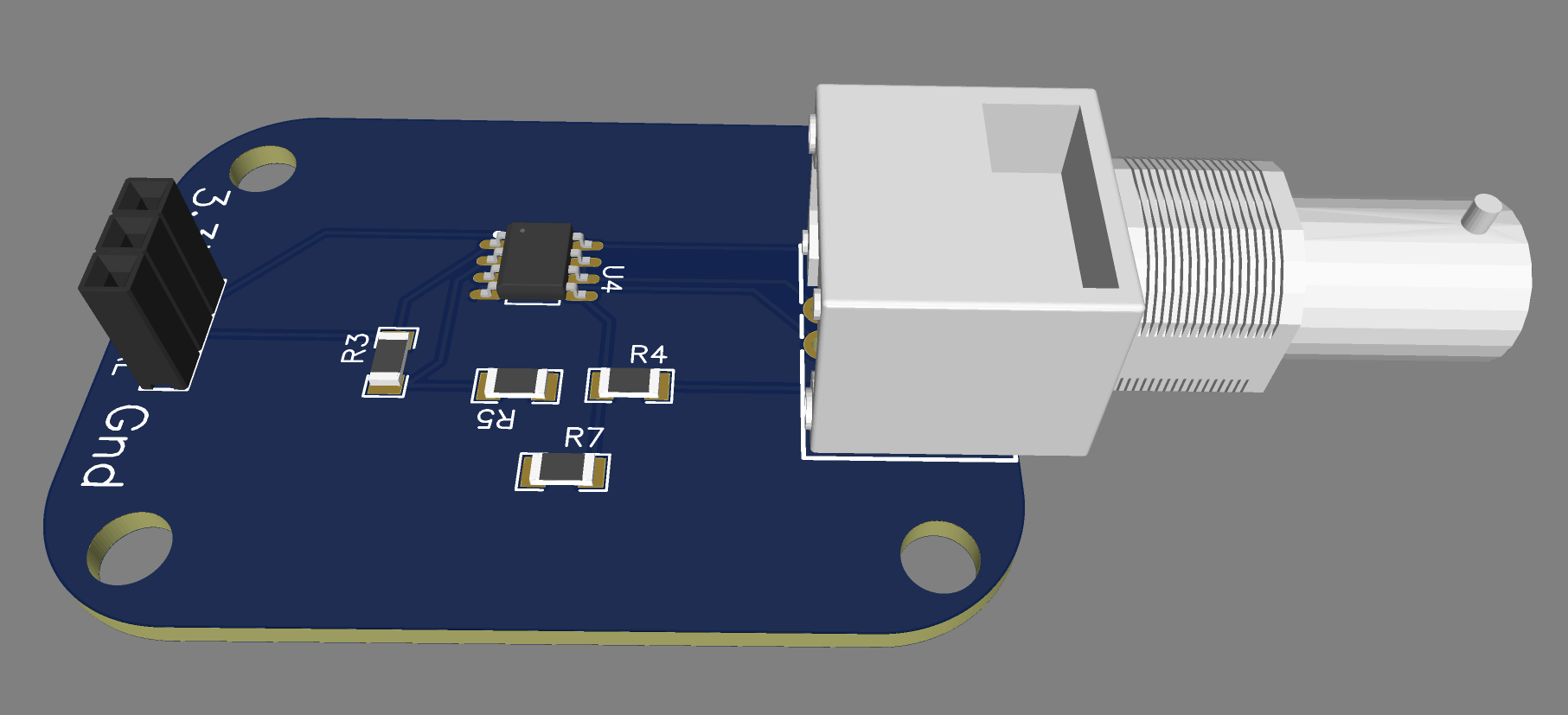
The problem of the current is solved by using an Op-Amp with input impedance of 1-100pA and prefered to be in the lower tens, the op-amp would probably be someting like j-fet type and we do not care about the slew rate of the op-amp as the pH probe is slow and the reaction time is in the seconds range. for the cheapest of those at DigiKey I would choose something like Microchip Technology MCP6L02T-E/SN with 8 legs and dual circuit in package like:
https://www.digikey.ca/en/products/detail/microchip-technology/MCP6L02T-E-SN/2059746
The cost of that op-amp is only $0.59 and to complete the circuit you only need 4 resistors to make the biasing and amplifying circuit
input bias is made by connecting 3.3V to VDD and a 10K resistor from 3.3V to +inB of the op-amp and then 2.2K resistor to ground. the ground of the pH sensor is connected to -inB and the pins OUTB and -inB are shorted together.
pH electrode output is connected to +inA
amplifiing of the siganl is made by connecting a 10K resistor between -inA and VSS and then 18K resistor from -inA to the ADC of the microcontroller, VSS pin is then connected to ground.
The circiut is now completed with 2.6X gain from the pH electrode and a bias of .595V.
the only thing missing is the BNC connector, and the cost of the project should be under $2 if right bnc and op-amp. (add $0.1 chinese RISCV mcu to complete system if you want), thermocouple amplifier should not need to be more than a resistor or and another op-amp, then if I use quad op-amp then I can use that, or a simple dallas one-wire sensor in a thermowell...
I made the circuit with LCSC parts and jlcpcb fabrication
@25C :
pH 0 = 0.470288V
pH 7 = 1.547V
pH 14= 2.623712V
To temperature compensate and calibrate, the code from superfly could ber used or the code from DfRobot,
superfly's code
https://codebender.cc/sketch:397462#DFRobot%20pH%20Sensor%20Calibration.ino
or DfRobot ph library:

 chris
chris
 Ted Sheflin
 Chris Johnson
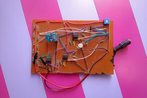
May I ask why we can't use a summing non inverting circuit to introduce the require bias ?