 M. Bindhammer
Overview
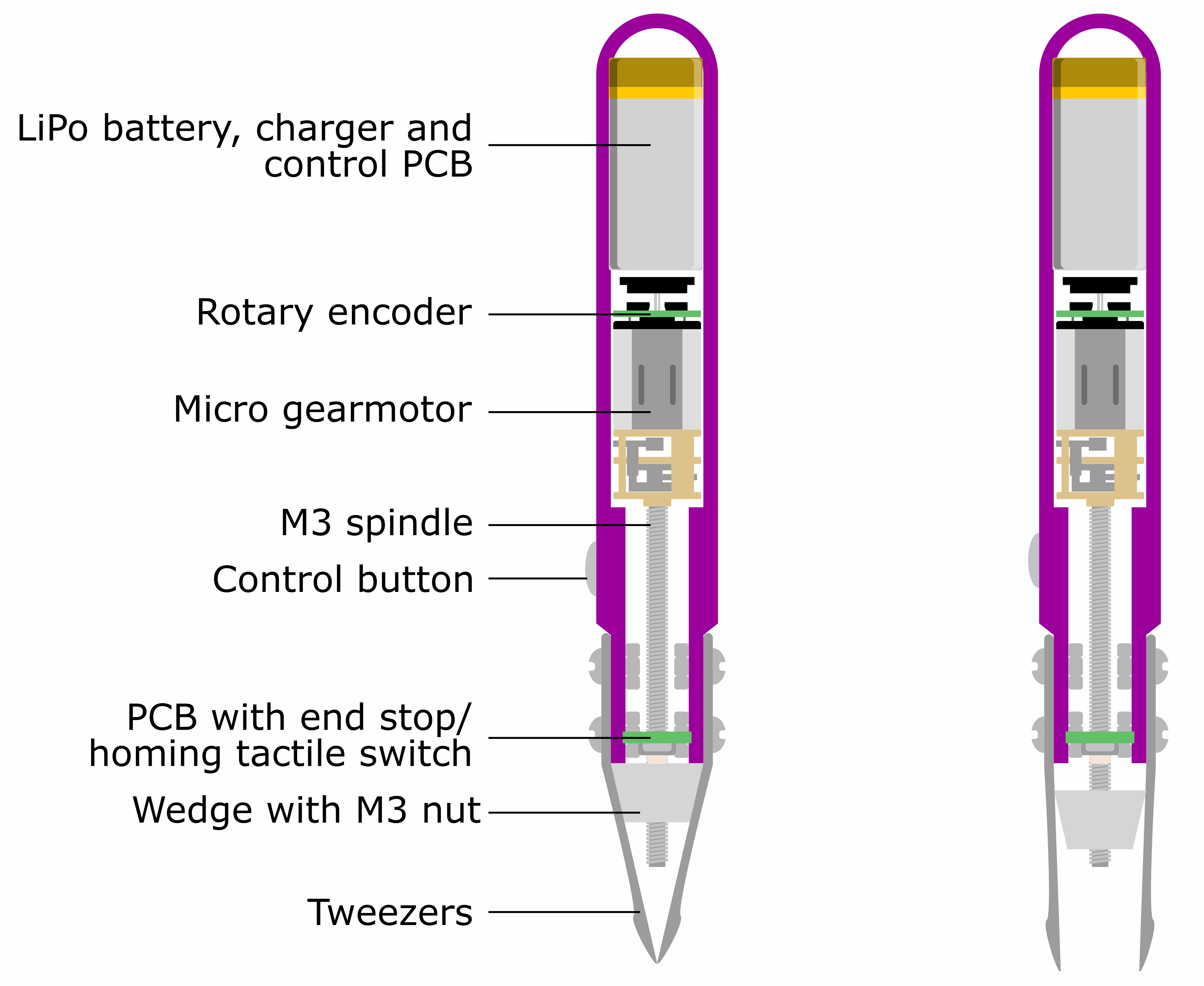
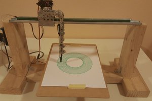
The following diagram shows the general design of the micro-robotic tweezers. It is clear that the control button plays an important role. My first thought was to use a thin film pressure sensor. The more pressure you apply, the wider the tweezers open. It would thus function similarly to cross tweezers, which, however, due to their design, allow too little control over the object held. Of course, you could also control the gripper by electromyography or a foot pedal.
Prototype
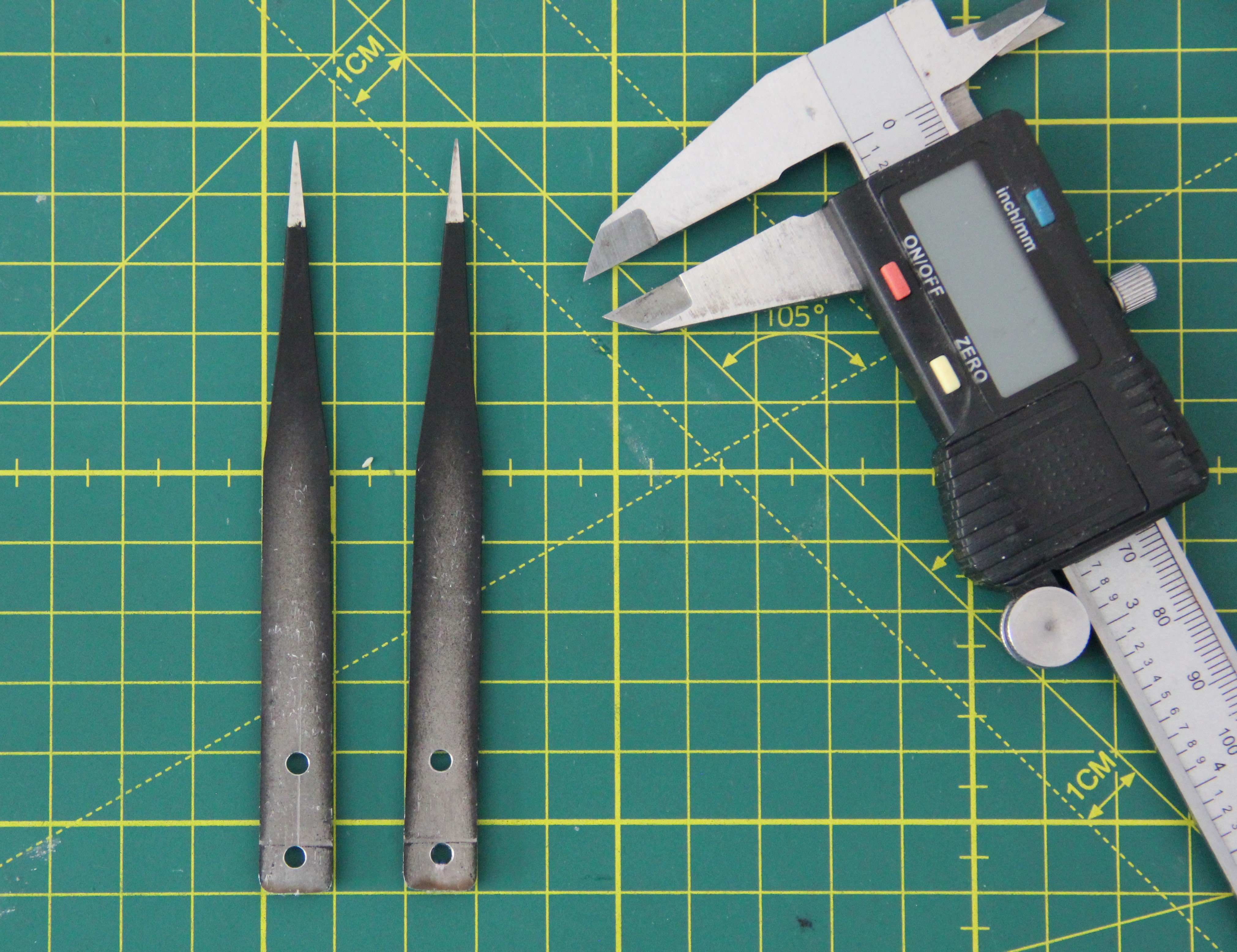
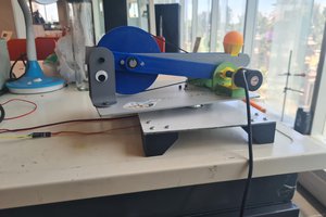
Before I start with 3D modeling, I decided to build a handmade prototype first. To do this, I sacrificed one of my tweezers, cut it into two pieces, and drilled 3mm mounting holes with my drill press.
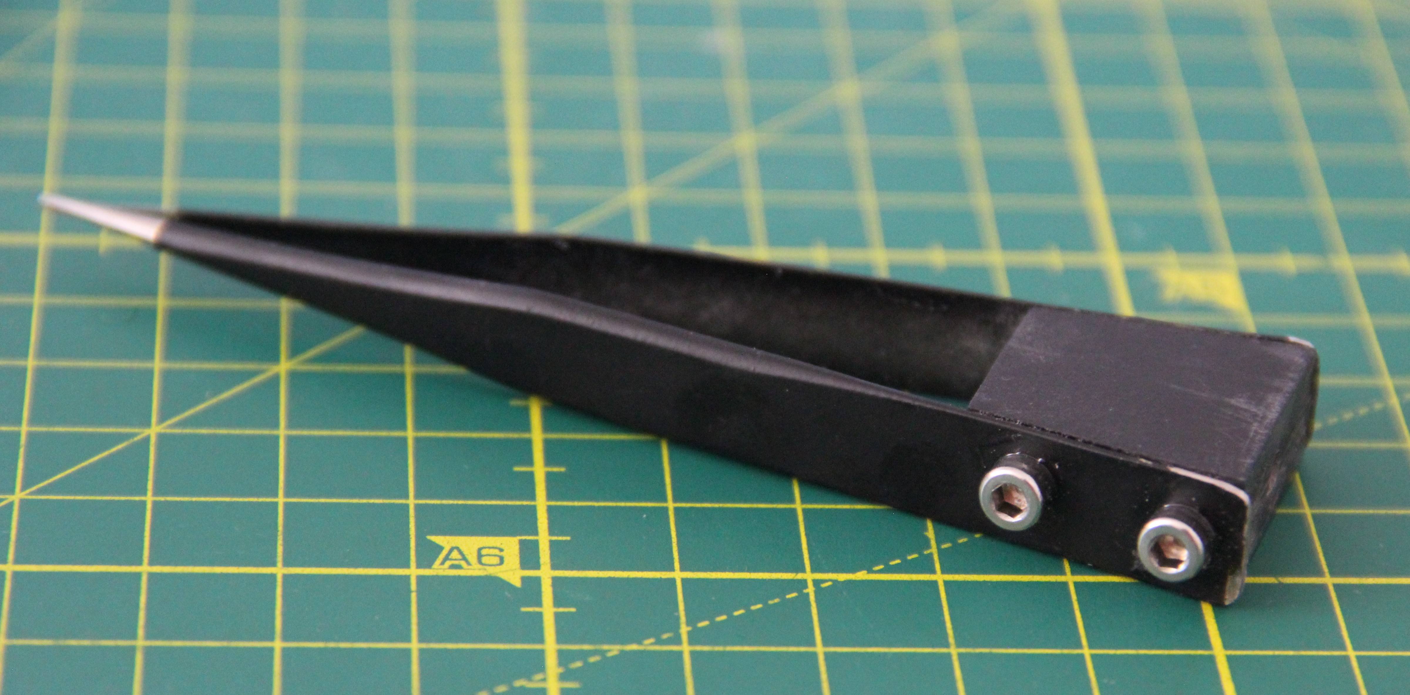
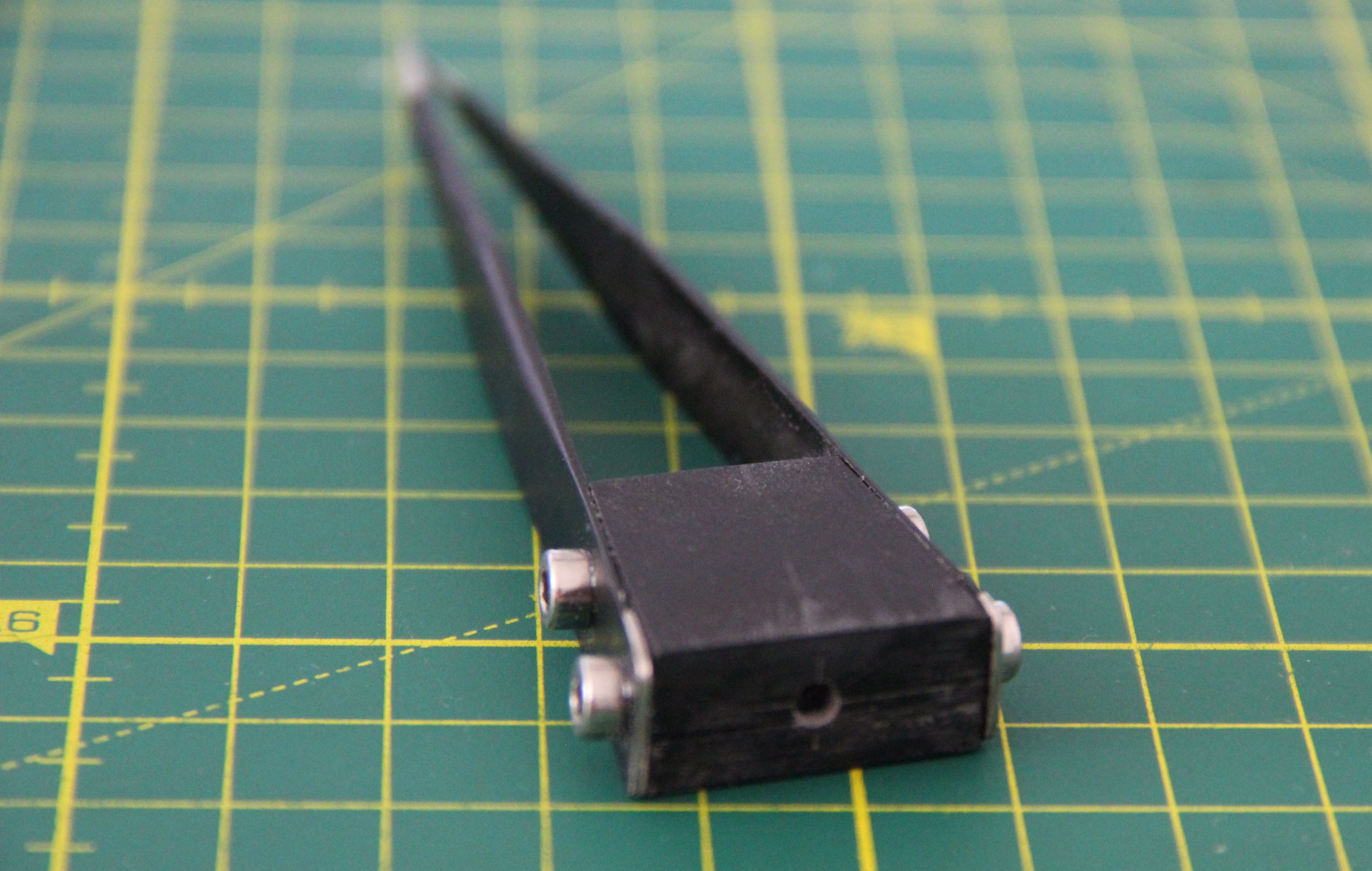
A corresponding wedge was cut out of a 10mm thick glass-fiber reinforced plastic plate, and ground, then four M3 threads were cut and an axial hole was drilled to accommodate the M3 motor spindle. The two halves of the tweezers were then screwed to the wedge using four M3 x 8mm stainless steel screws.
Here are some more parts I want to use for the prototype:
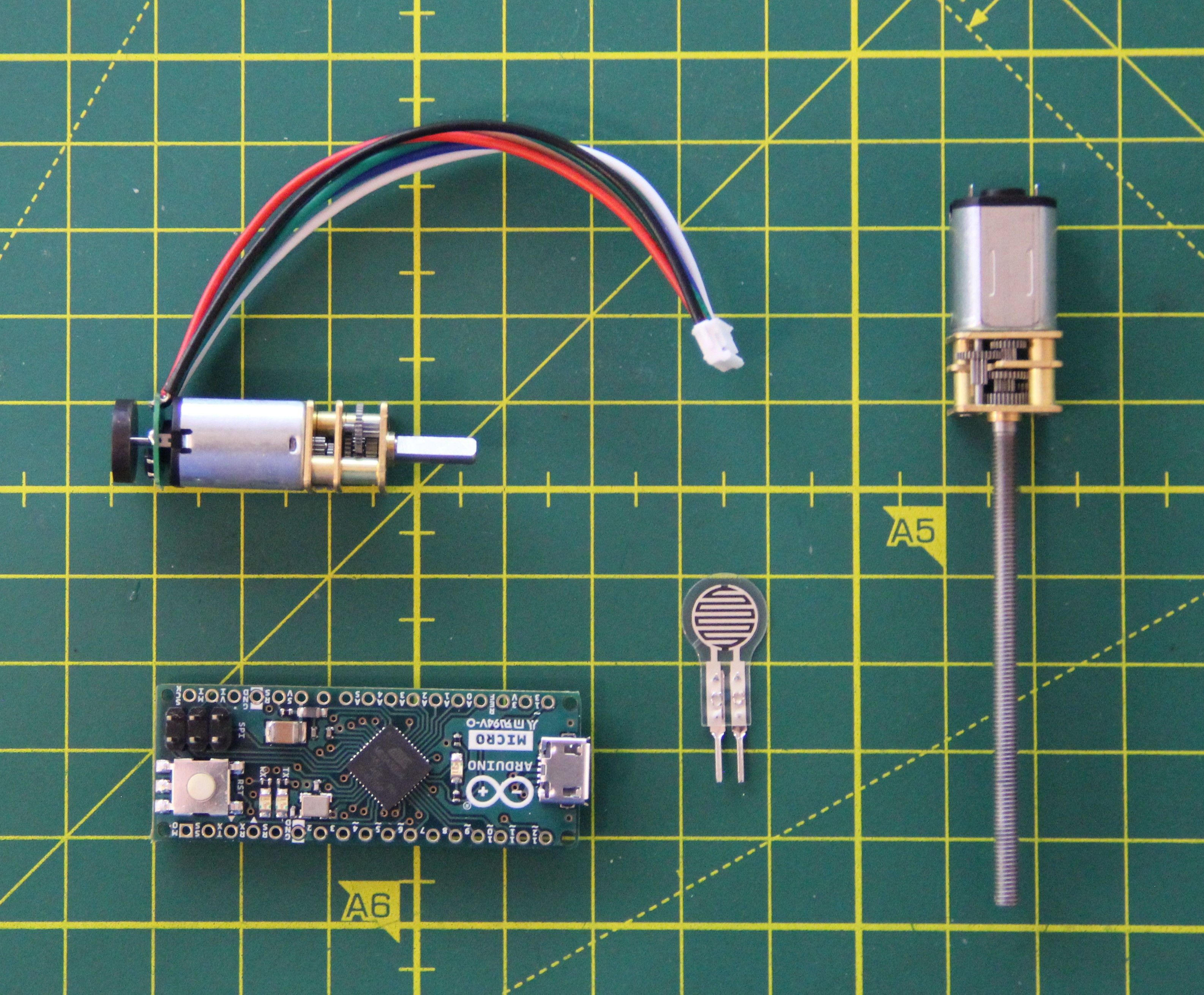
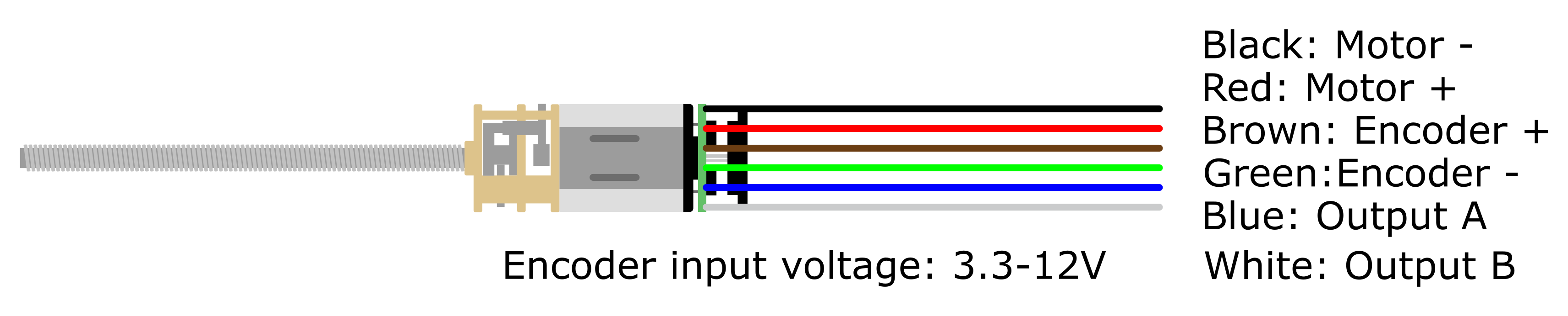
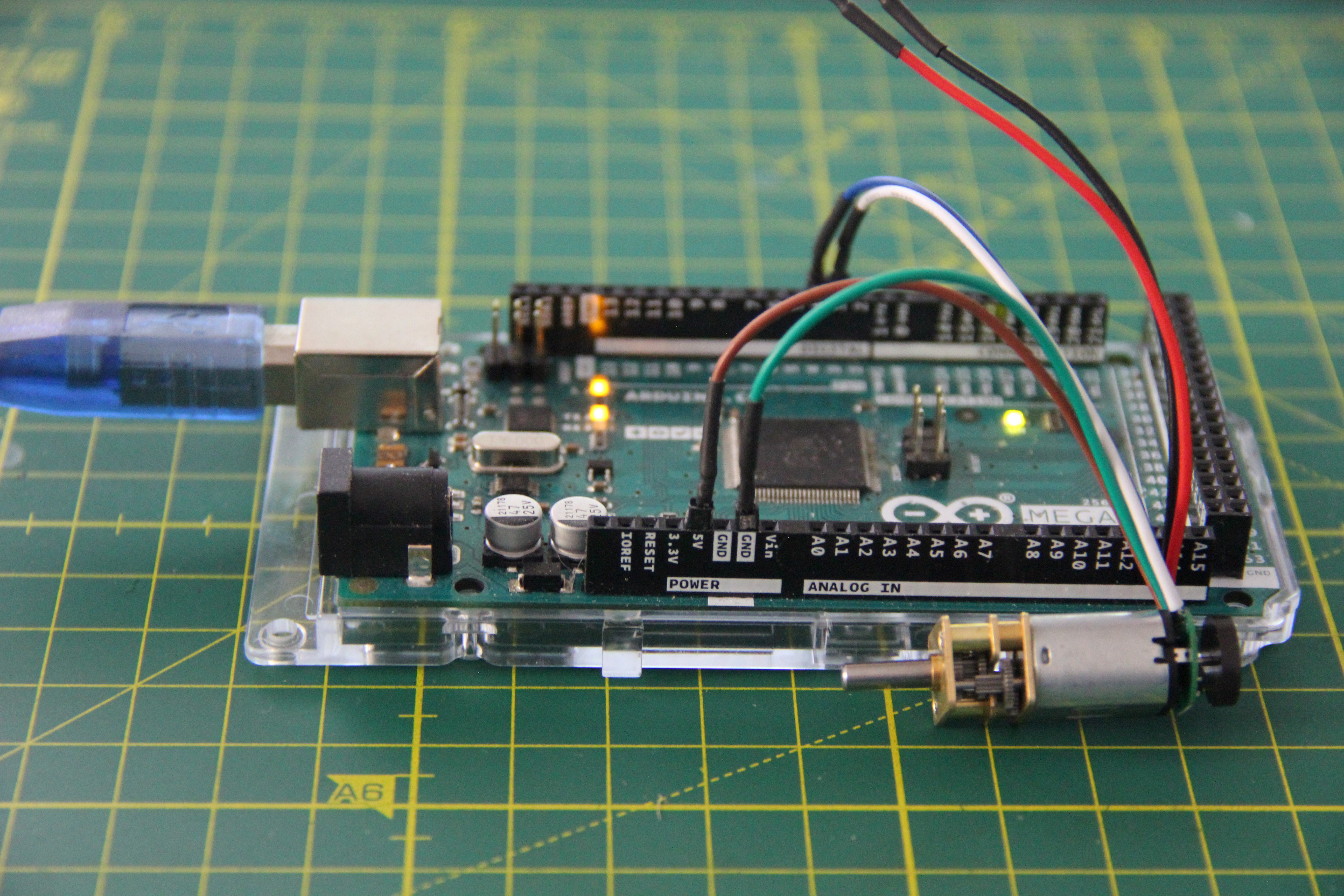
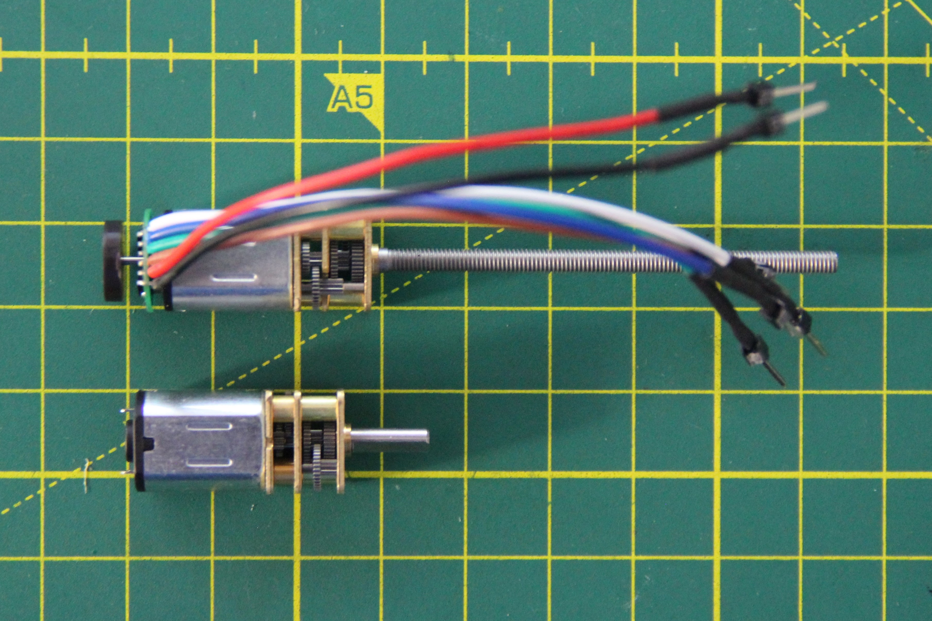
Unfortunately, I could not find a micro gearmotor with an M3 spindle and rotary encoder. I bought another motor with a rotary encoder, which I have to exchange.

This work is licensed under a Creative Commons Attribution-NonCommercial 4.0 International License.
 Antonio Lopez
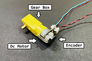
 Sagar 001
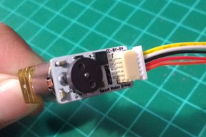
 Danny FR