 Vijay
VijayI spent a few days on Proteus simulating the circuit and was dismayed that is didnt work
Then I found amazing documentation by Frederic L on his Flip Dot Display Controller project ( https://hackaday.io/project/159415-flip-dot-display-diy-controller ), and was pleasently surprised that we had a similar approach using Source and Sink Trasistor Arrays, but used Shift-Registers instead of Decoders.
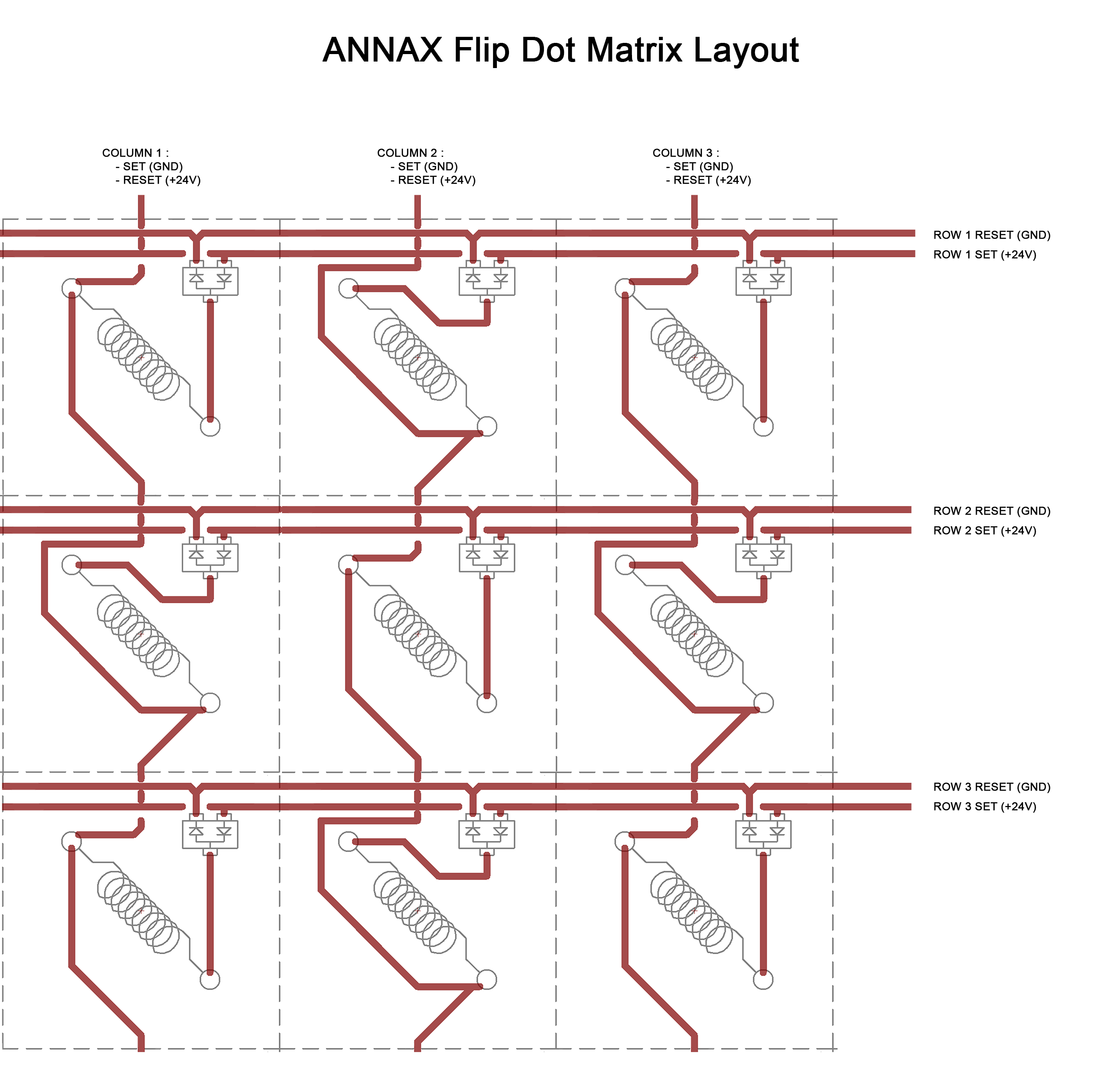
Trying to figure out why my circuit wouldnt work [ Seems that I cant connect the outputs of the Source and Sink trasistor arrays together directly if I want the circuit to work on Proteus atleast], I found on one of his log that the Flip-Dot pannel has some additional components, namely Swiching diodes placed between the Source and Sink on each coil:
When added these into the circuit, things still wouldnt work, as then proceeded to add one switching resistor pair to the common conenction of the coils for each module, and voila!
The Above Video shows the working simulation. I used UDN2981's for the source drivers and ULN2803's for the SINK, analogous to the ones I chose before in the last log. All the pins of a single module are arranged in a vertical line and show only 2 modules for simplicity.
As a suggestion by kelvinA on the previous log, I've used the Active Low enable pins of the Decoder IC and connected them to SET/RESET in a way to prevent shoot-through condition of the H bridge.
The next step is designing the board with this schematic!
Discussions
Become a Hackaday.io Member
Create an account to leave a comment. Already have an account? Log In.