 Vijay
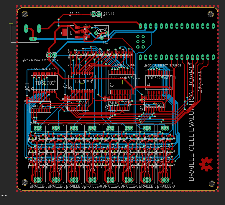
VijayI created an 8 - Braille cell board to evaluate the braille cell functionality.
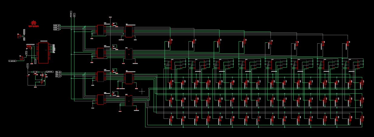
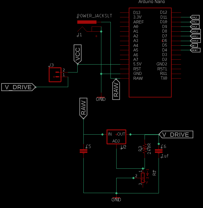
A similar schematic as described in the previous log added an Arduino Nano to control the pins.
I've Added an adjustable LM317, so that I can specify the voltage that is given to drive the pins since this aspect still is to be calibrated.
The final board layout looks like this:
This will be a reference example for a driver/carrier board for individual braille cell modules.
The PCB for the braille cell module is pretty simple:
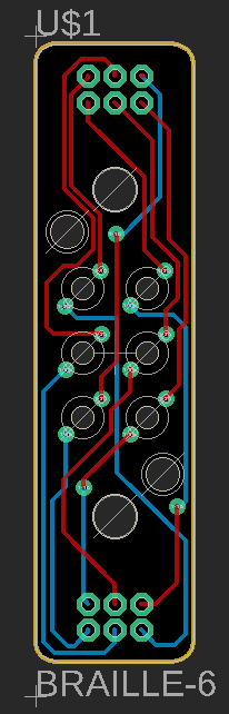
Ive used vias to which they will be soldered. make sure the Vias has the copper exposed on the solder mask when getting the PCBs made.
Finally, Ive created an eagle library for the footprint for the braille cells, so it is easy to use the footprint to create custom baseboards as per requirement.
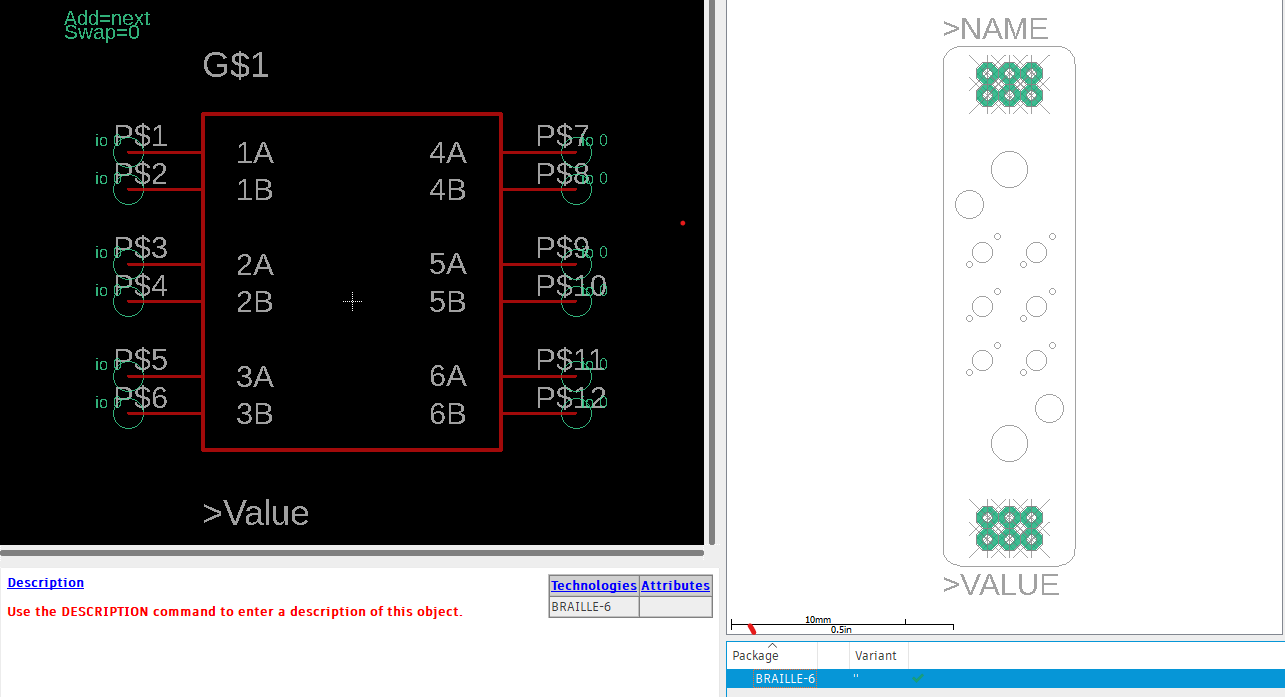
Download the Braille Cell Evaluation Board Eagle Source Files here
Download the Braille Module Eagle Source Files here
Download the Footprint Library of the braille cell for Eagle here
Discussions
Become a Hackaday.io Member
Create an account to leave a comment. Already have an account? Log In.