 wlf647
It’s alive! In today’s update I’ll be describing the complete circuit and post a short video of everything working together for the first time.
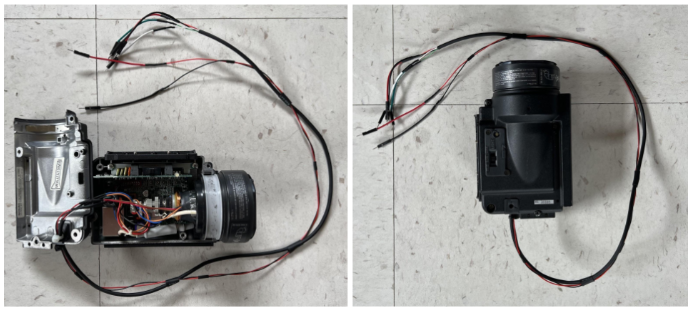
First things first, to make the CRT display easier to work with (see last update), I created this wire harness for it. It has 6 conductors, 2 for power and 2 each for horizontal and vertical deflection.
The circuit
The circuit is built on two separate breadboards, as shown in the photo below. The large main board has everything on it except for the accelerometer, which is on the small board. The small board will eventually be mounted on the display so it can measure the acceleration of the display (i.e. the “box”) as it is moved around in space. I’ll probably rebuild / solder the small board on a perfboard for that.
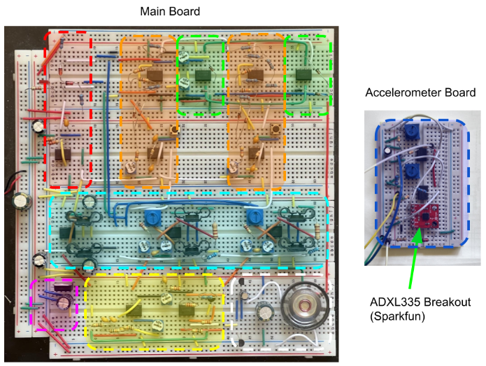
I have uploaded the full schematics to the schematics section of this hackaday project. I’ll briefly go over the different components now one by one, referencing the colored boxes in the breadboard photo. Each box has a corresponding section in the schematics, which has all the details.
Split supply and reference voltages (top left, red box)
The circuit uses a split supply with +7.5V, -7.5V, and a 0V ground reference. I don’t have a bench split supply so I’m feeding in 15V from my bench supply and splitting with a resistor divider to create GND halfway between the rails. This ground reference is buffered by an op amp and is only used for small loads, like deriving the VRef+ and VRef- reference voltages with 5.1V Zener diodes.
Accelerometer board (small board, blue box)
Nothing too much going on here, I use a Zener diode to set up the 3.3V power for the ADXL335 chip. The chip outputs 3 analog voltages proportional to the chip’s acceleration in 3 dimensions. Sensitivity is around 300mV/g, with 0g about halfway between the chip’s positive and negative rail. I use two op amps to first buffer the output of two dimensions, then amplify it x3 and add an offset so that 0g is at GND.
A few more details on the accelerometer board. I played with the lowpass filter capacitors but ended up using the default values from the breakout (100nF), which amounts to 50Hz bandwidth. I also tried another accelerometer chip, the ADXL326. It is the same as the ADXL335, but less sensitive. It detects up to +/-16g, instead of +/-3g. I first thought that shaking the display might create more than 3g acceleration, but that wasn’t really the case. So I stuck with the 335 and its +/-3g range.
X and Y physics logic (2 orange boxes)
The entire physics simulation happens in the two orange boxes. The physics behind the ball’s motion in X and Y direction are independent in this simulation, so there are two separate circuits/orange boxes, one for X and one for Y.
In each box, the bottom 8DIP chip makes up two op amp integrators: a first one that integrates the ball’s acceleration over time to produce velocity, and a second one that integrates that velocity over time to get the ball’s position.
At the top of each orange box is the “bounce circuit” (2 op amps each). This circuit detects collisions with the top/bottom or left/right edges of the screen and provides the force that accelerates the ball back in the opposite direction, much like a spring. For example, when the ball’s X position goes over the right side of the screen by a few mV (full screen width is set by VRef- and VRef+, or -5.1V to 5.1V), the bounce circuit will produce a large negative voltage, 100x the penetration depth (set by R11 and R15 in the schematics), which is fed to the acceleration input for X and makes the ball bounce back to the left.
I hope this short description makes some sense. I want to quickly cover the overall circuit today and plan to dive deeper into the choice and physical interpretation of components and values in the next update.
Bounce sound trigger logic (2 green boxes)
Yes, there is a bouncing sound effect :) I’ve seen this in other ball-in-box implementations and IMO it adds a ton to the realism of the simulation. Definitely worth the few additional parts.
The bounce sound effect gets triggered when the bounce force (see physics logic) exceeds a threshold, set by a trim pot. The bounce sound is simply the 1.3kHz oscillator signal that is also used to draw the ball on the screen.
Loudspeaker and driver (white box)
When a bounce sound is triggered, the 1.3kHz tone from the oscillator gets amplified and played through this speaker.
Sine wave oscillator (yellow box)
The main purpose of this circuit is to create a time-varying X and Y position signal to draw a round ball on the screen. It is a 1.3kHz sine wave and a corresponding cosine, or 90 degree shifted version, generated by a standard phase-shift oscillator plus a tunable phase-shift circuit. The sine and cosine output of this oscillator circuit are added to the ball's X and Y position from the physics circuit, which results in the CRT drawing a circle at the position of the ball. The oscillator is also used to create the bounce sound effect (see above).
CRT deflection driver (cyan box)
The X and Y position from the physics logic (with the ball sine/cosine signal added) directly drive the horizontal (X) and vertical (Y) deflection coils of the CRT. I’ve shown in the last update how to drive the coils in principle, more details are in the schematics. There are three push-pull stages: one to drive the X coil, one to drive the Y coil, and one as a current return path (GND) for both X and Y coils.
It takes a lot of current to drive these deflection coils. To hold the ball at the left or right edge of the screen, the horizontal coil must carry 180mA DC. The coil’s DC resistance is only 4 Ohms, that means most of the 15V supply voltage drops at the top and bottom side drive transistors, about 1.2W per transistor! That’s why these transistors have heatsinks. They still get quite hot during operation.
A few more details: I noticed some ringing in the coil current that stopped when I added a damper resistor in parallel. Fun fact, in the photo you can see these ½ W resistors. They are 1/2 W because I thought they were getting hot, but it was just the proximity to the transistors. They dissipate tiny amounts of power, a ¼ W resistor is totally fine here.
Display power supply (magenta box)
This is just a 7812 voltage regulator to bring the 15V supply voltage down to 12V, to power the Sony viewfinder.
The video
Here’s a video of the complete system working for the first time. Apologies for the portrait video, but that was the easiest way to get both the moving accelerometer board and display into the shot. I’m super stoked it all works as intended!
Next steps
- Attach the accelerator board to the display. I will probably rebuild the circuit on a perfboard and add the accelerometer-to-mainboard cables to the display’s wire harness.
- Record a fun video of the final system
- Write up more details on how the physics circuit works, maybe show some scope traces
- Write up the math / theory behind the physics
- Write up what didn't get done in time, possible future work
Discussions
Become a Hackaday.io Member
Create an account to leave a comment. Already have an account? Log In.