 wlf647
Moving the circuit to PCB
I decided that this project is worth keeping around on a PCB, so I designed two boards in KiCad. I tried out PCBWay’s KiCad plugin for the first time, and it worked like a charm. It takes literally one click to generate all the fabrication files and upload them to PCBWay. Pretty cool!
I had made a few careless mistakes during layout (a handful of vias were tented, even though I wanted all of them to be open), which PCBWay thankfully caught and fixed for me. The boards still arrived within less than a week, and they are flawless:
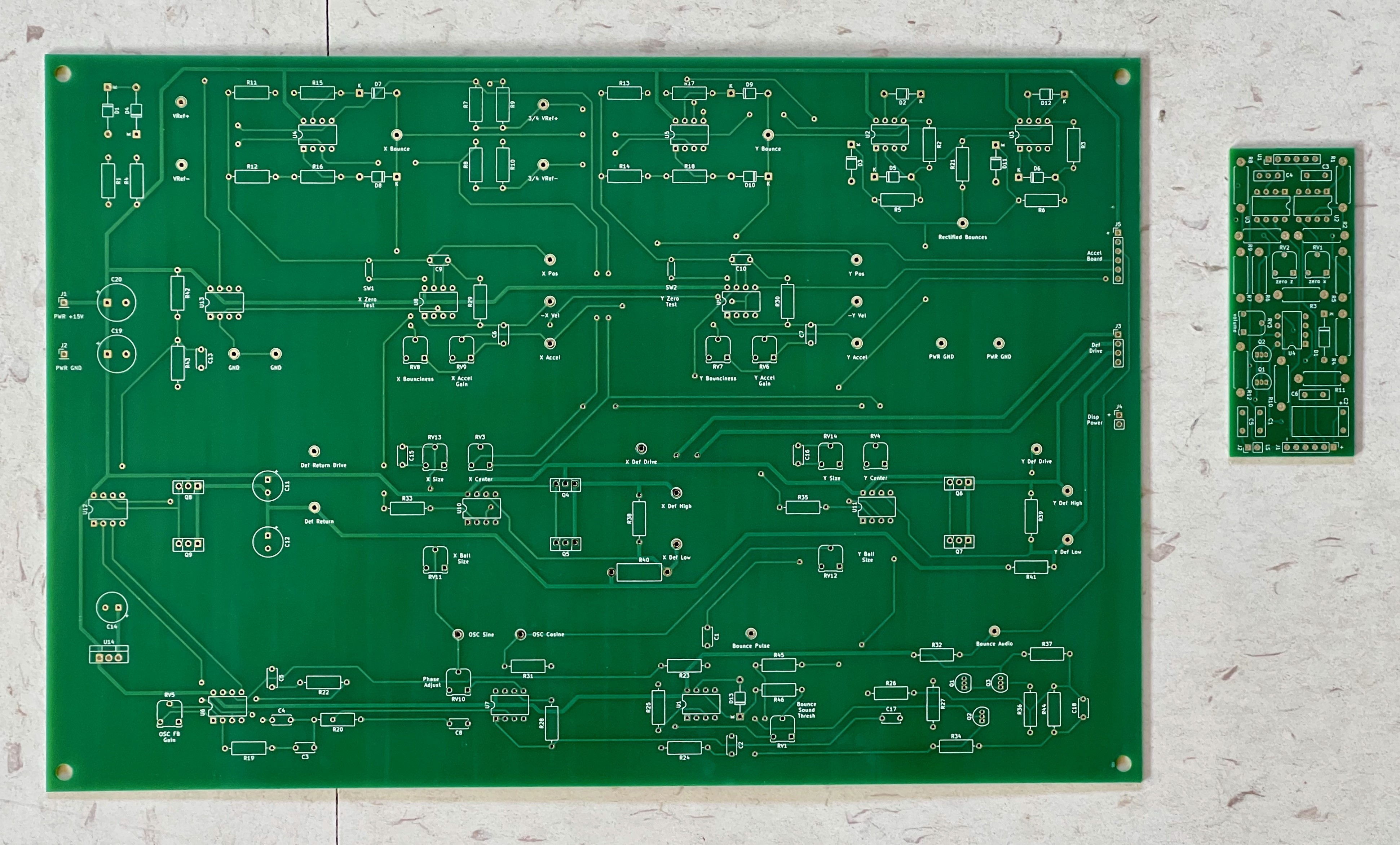
For the main board, I went with what I would call an “educational” layout :). I imagined a circuit board you might see in electronics class at school. It’s easy to identify the subcircuits and there are lots of labeled test points to hook up your scope and look at waveforms. All components are through-hole because I already had all the parts that way. It is also era-appropriate for this circuit :) The accelerometer is an SMT part, but I’m using the SparkFun module which breaks out the pins to more convenient through-hole pads.
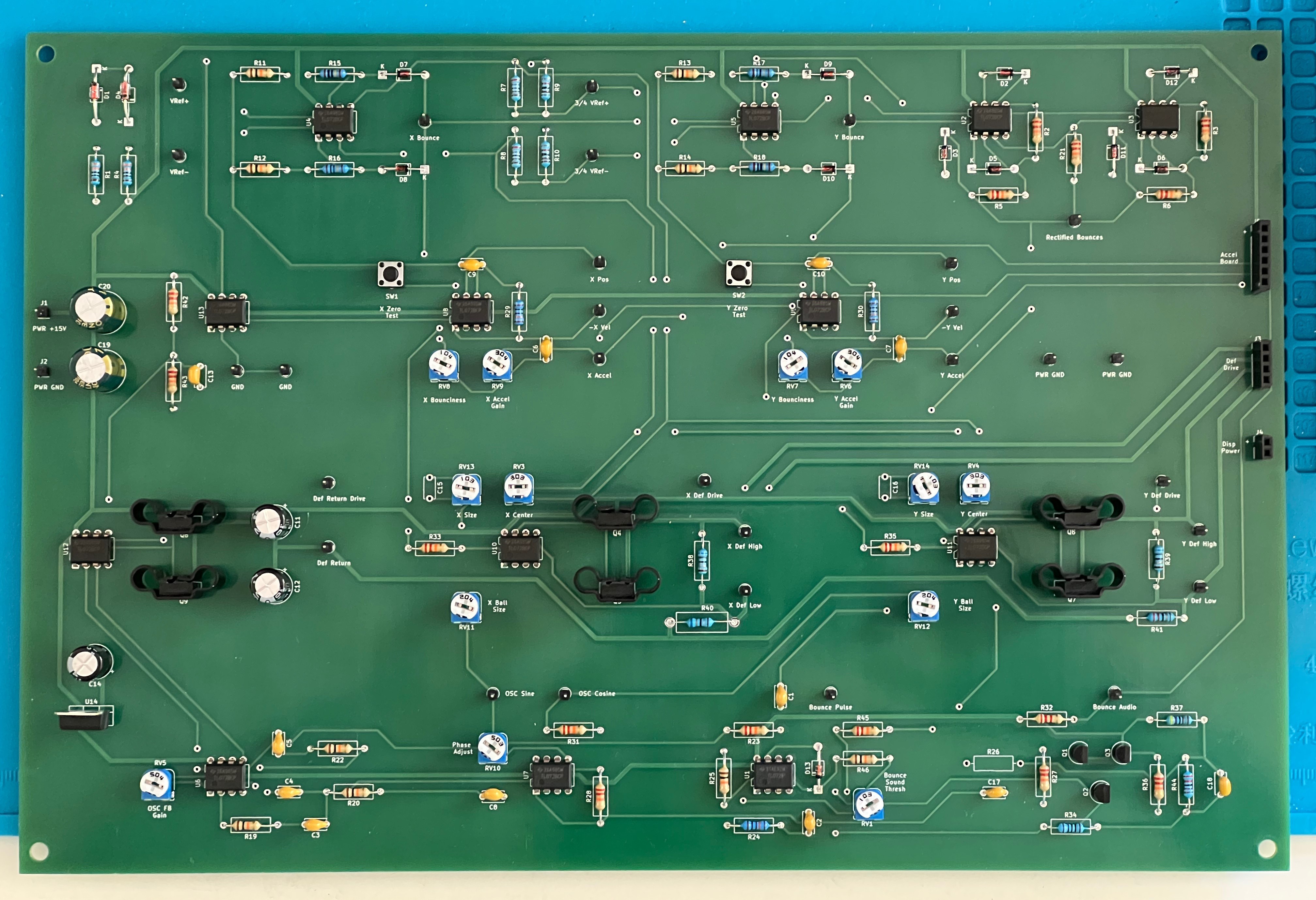
Here is the fully assembled main board:
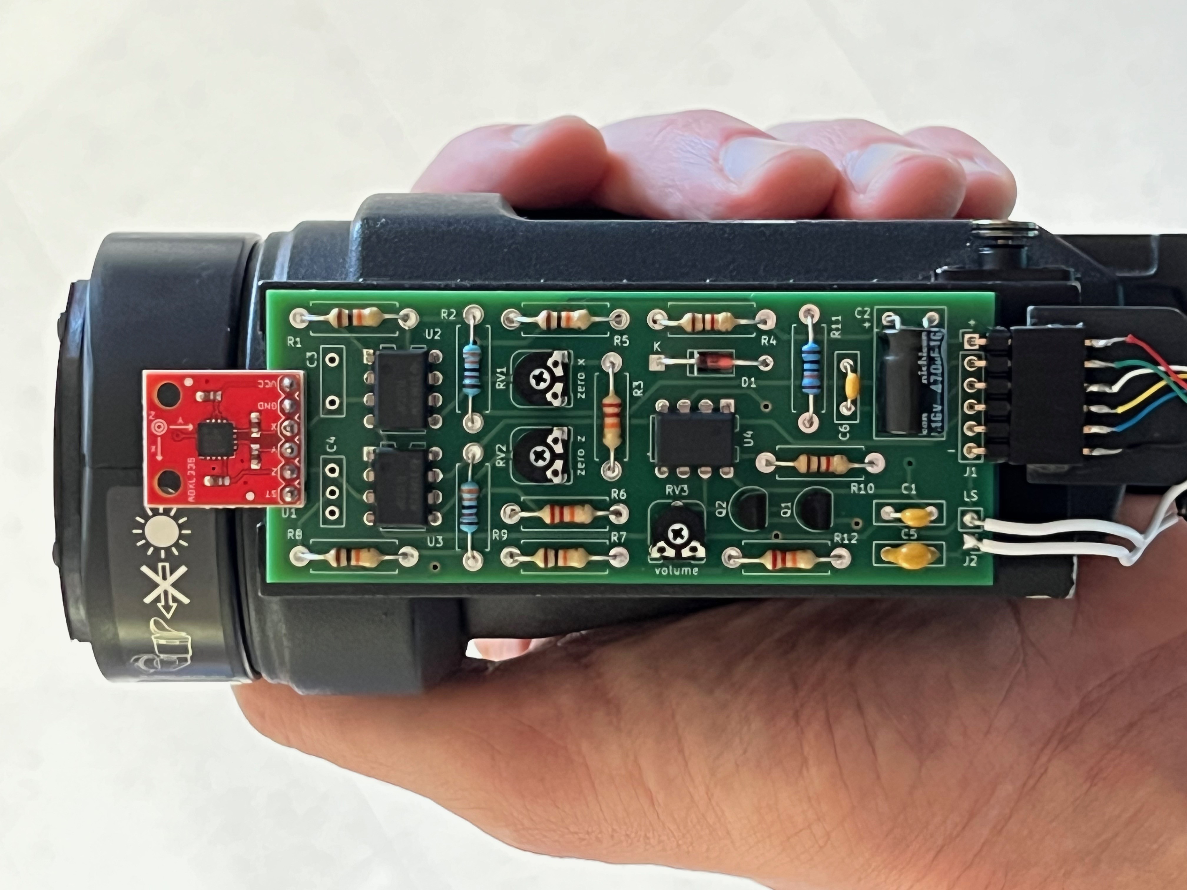
And here is the fully assembled accelerometer board, mounted to the display:
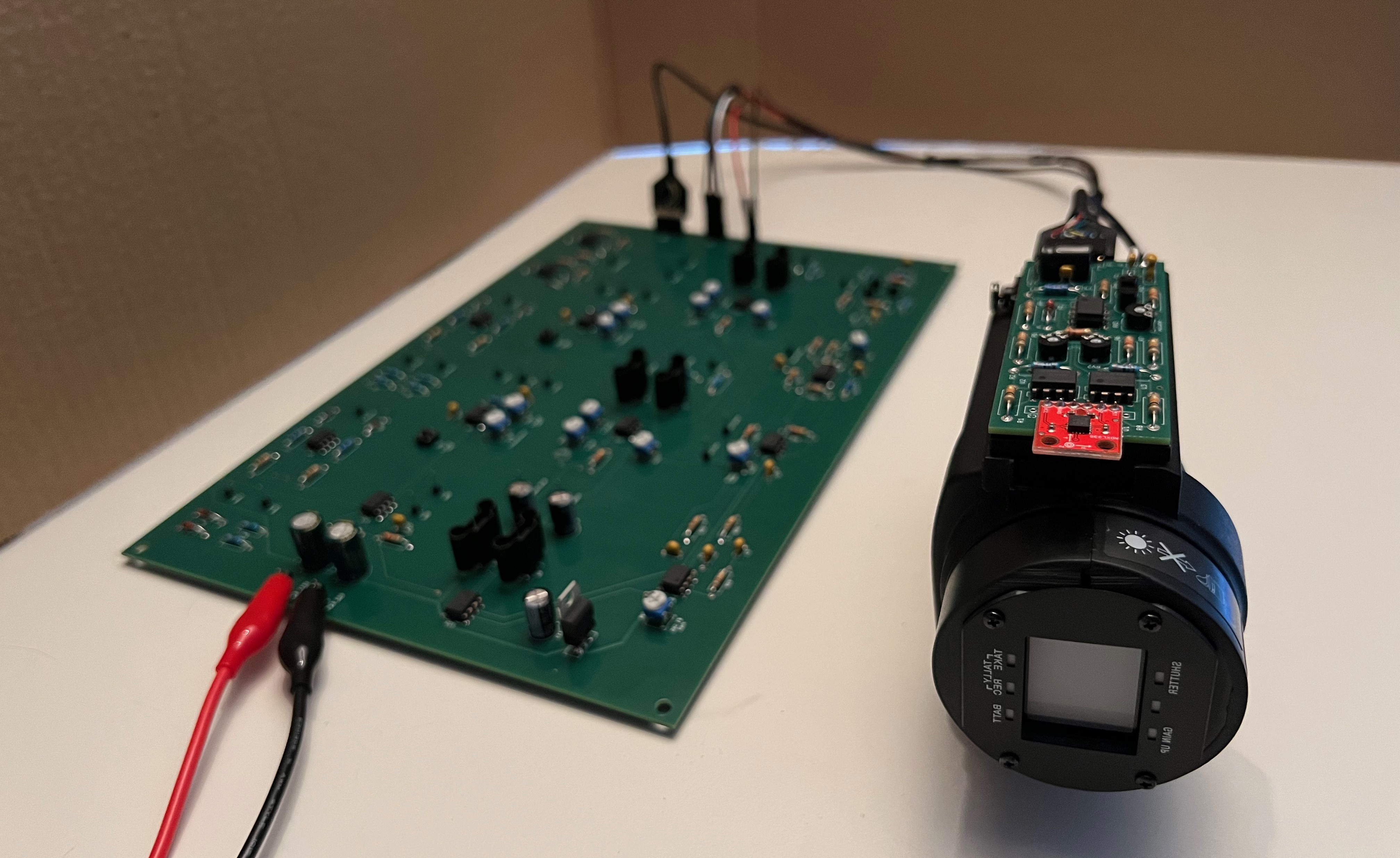
The full system on PCB:
Improved sound effects
I couldn’t resist making a few tweaks to the circuit before hardening it on a PCB. The most significant one is better audio. The original approach of playing a 1kHz tone for the duration of the bounce was effective for how simple it was, but I somehow couldn’t dial it in to where lighter bounces really sounded lighter.
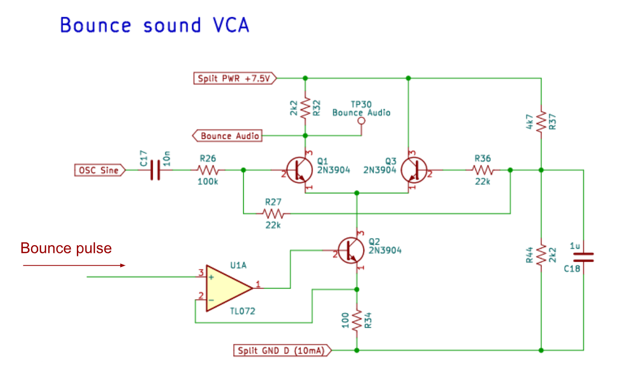
So I added a voltage controlled amplifier that varies the volume with the depth of the bounce. You can see the VCA in the bottom right of the main PCB. It’s a basic long tail pair with 3 NPN transistors, the schematic is shown below. The full updated schematics are uploaded here on hackaday.
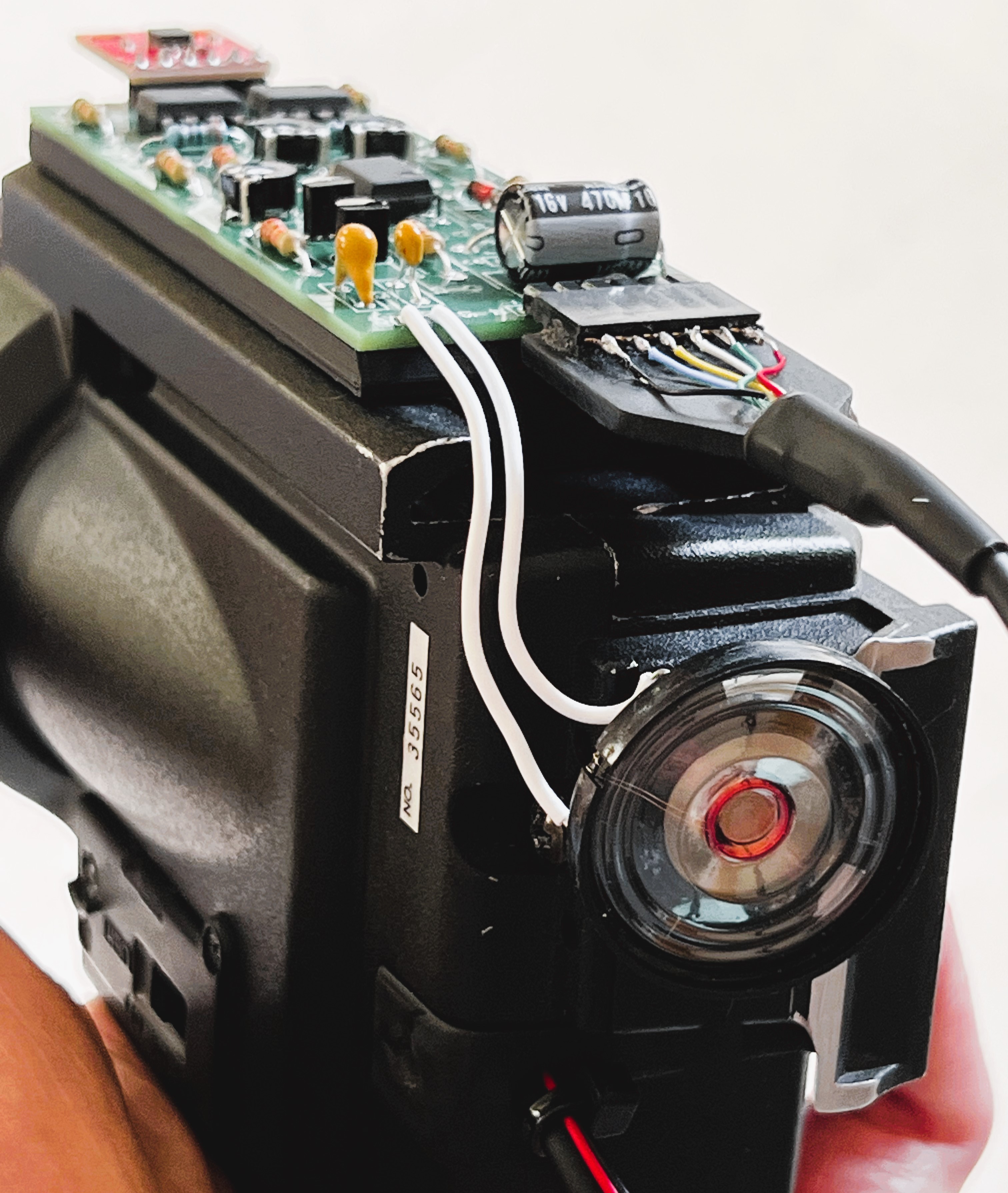
I also decided to move the speaker from the main board to the display, so that the bounce sound effect comes from the right direction. This is shown in the picture below. I had to play with the positioning of the speaker a bit, since the strong permanent magnet can easily distort the CRT picture.
Fixed display flicker
I noticed a slight flickering in the display so I took a second look at the brightness signal coming at G1 of the CRT. It turns out the brightness voltage was not actually constant as I had hoped, but was periodically pulled down to completely black/off during what looks like horizontal and vertical blank (retrace) periods.
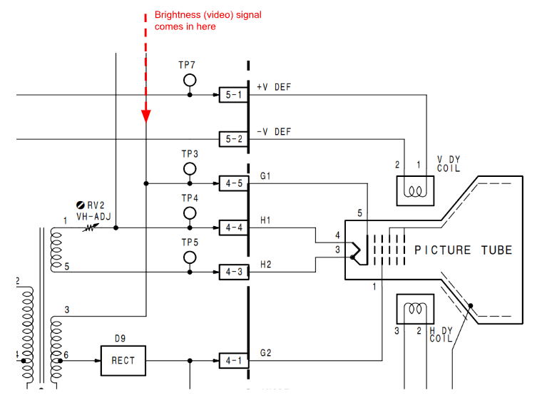
In retrospect, it makes sense, looking at the rest of the viewfinder schematic. I’m not quite sure why the ~60Hz vertical flicker didn’t show up more clearly in the videos I made earlier? Either way, to fix the issue I disconnected G1 from the video circuit and connected it to 12V DC (display power rail) through a 1M resistor.
Miscellaneous tuning
- Double checked the resistors that are parallel to the deflection coil to dampen ringing and decided to lower their value from 120 Ohms to 68 Ohms.
- Repurposed unused op amps in as additional virtual GND buffers
Updated demo video
Finally, I recorded another short video that shows the PCBified system. Enjoy!
Discussions
Become a Hackaday.io Member
Create an account to leave a comment. Already have an account? Log In.