 Christoph
We're working with the "Chonker H735" board which was developed solely for the purpose of bringing up the BF target.
Repo: https://github.com/crteensy/yolo-chonker
Several of these were built, some with just the base necessities like
- MCU and optional 8 MHz resonator
- USB connector
- 3V3 regulator
- two LEDs on GPIOs
Writing basic blinky code in STM32CubeIDE won't get us the desired files we need for the BF target, but it's easy and provides us with:
- some valid linker script
- some valid startup code
- a valid (limited) clock tree setup
The main() function then might look like this:
int main(void)
{
  HAL_Init();
  SystemClock_Config();
  MX_GPIO_Init();
  while (1)
  {
	HAL_Delay(500);
	HAL_GPIO_TogglePin(led_blue_A10_GPIO_Port, led_blue_A10_Pin);
  }
}
There's not a lot we could remove from this. Some things to note though:
- HAL_Init() is called first,
- even before SystemClock_Config(),
- and then we initialize the actual peripherals.
However, there's a lot of stuff happening before main() is even entered: that's the startup code which includes the reset handler. It's written in assembler, but the first thing it does after setting up the stack pointer is to call SystemInit(), which is written in C again:
startup_stm32h735vghx.s:
Reset_Handler:
  ldr   sp, =_estack      /* set stack pointer */

/* Call the clock system initialization function.*/
  bl  SystemInit
...
system_stm32h7xx.c:
void SystemInit (void)
{
#if defined (DATA_IN_D2_SRAM)
 __IO uint32_t tmpreg;
#endif /* DATA_IN_D2_SRAM */
...
SystemInit() configures things like FPU, Flash timing, available oscillators (there are a few of them, both internal and external), resets the PLL, and configures the interrupt vector table.
After that, we're back in the asm startup code (startup_stm32h735vghx.s) with a bunch of snippets like this one:
/* Copy the data segment initializers from flash to SRAM */
  ldr r0, =_sdata
  ldr r1, =_edata
  ldr r2, =_sidata
  movs r3, #0
  b LoopCopyDataInit

CopyDataInit:
  ldr r4, [r2, r3]
  str r4, [r0, r3]
  adds r3, r3, #4

LoopCopyDataInit:
  adds r4, r0, r3
  cmp r4, r1
  bcc CopyDataInit
_sdata, _edata and _sidata are defined in the linker script. The snippet shown above copies data from flash to RAM. This data is used to initialize variables that were defined an initialized somewhere in the code, for example:
static uint8_t foo = 3;The initialization value can only be stored in flash to survive a reset, but the variable itself resides in RAM during runtime - so the init code has to copy the init value to that RAM location during startup to prepare everything for the code that later relies on that variable to be properly initialized.
There are other sections for variables that are initialized to zero, or not initialized at all. What we need to know now is what sections are generated by STM32CubeIDE, so that we can compare those sections with the sections in a linker script used in a working BF target.
Each of these sections has to be placed in some memory area (like flash, or RAM, and some sub-areas of those). These must be known and defined.
CubeIDE's generated linker script (STM32H735VGHX_FLASH.ld) creates these memory areas:
MEMORY
{
  ITCMRAM (xrw)    : ORIGIN = 0x00000000,   LENGTH = 64K
  DTCMRAM (xrw)    : ORIGIN = 0x20000000,   LENGTH = 128K
  FLASH    (rx)    : ORIGIN = 0x08000000,   LENGTH = 1024K
  RAM_D1  (xrw)    : ORIGIN = 0x24000000,   LENGTH = 320K
  RAM_D2  (xrw)    : ORIGIN = 0x30000000,   LENGTH = 32K
  RAM_D3  (xrw)    : ORIGIN = 0x38000000,   LENGTH = 16K
}
and these sections:
.isr_vector
.text
.rodata
.ARM.extab
.ARM
.preinit_array
.init_array
.fini_array
.data
.bss
._user_heap_stack
As written above, _sdata, _edata and _sidata are defined in the linker script. Here's the part that does that:
  /* used by the startup to initialize data */
  _sidata = LOADADDR(.data);

  /* Initialized data sections goes into RAM, load LMA copy after code */
  .data :
  {
    . = ALIGN(4);
    _sdata = .;        /* create a global symbol at data start */
    *(.data)           /* .data sections */
    *(.data*)          /* .data* sections */
    *(.RamFunc)        /* .RamFunc sections */
    *(.RamFunc*)       /* .RamFunc* sections */

    . = ALIGN(4);
    _edata = .;        /* define a global symbol at data end */
  } >RAM_D1 AT> FLASH
.data is a label for the whole section, and _sidata, _sdata and _edata are actual addresses for the start and end addresses of that section. The script also states that variables within this section reside in RAM_D1, and that their initialization values are to be stored in FLASH - they occupy space in both areas.
We have to keep these lists of memory areas and sections in mind for a later comparison with BF's way of doing this.
When all memory is initialized by the startup code, it will call libc to execute more constructors and then finally branch to main():
int main(void)
{
  HAL_Init();
  SystemClock_Config();
  MX_GPIO_Init();
  while (1)
  {
...
main then carries out HAL initialization before configuring the final system clocks for the application:
void SystemClock_Config(void)
{
  RCC_OscInitTypeDef RCC_OscInitStruct = {0};
  RCC_ClkInitTypeDef RCC_ClkInitStruct = {0};

  /** Supply configuration update enable
  */
  HAL_PWREx_ConfigSupply(PWR_DIRECT_SMPS_SUPPLY);

  /** Configure the main internal regulator output voltage
  */
  __HAL_PWR_VOLTAGESCALING_CONFIG(PWR_REGULATOR_VOLTAGE_SCALE1);

  while(!__HAL_PWR_GET_FLAG(PWR_FLAG_VOSRDY)) {}

  /** Initializes the RCC Oscillators according to the specified parameters
  * in the RCC_OscInitTypeDef structure.
  */
  RCC_OscInitStruct.OscillatorType = RCC_OSCILLATORTYPE_HSE;
  RCC_OscInitStruct.HSEState = RCC_HSE_ON;
  RCC_OscInitStruct.PLL.PLLState = RCC_PLL_ON;
  RCC_OscInitStruct.PLL.PLLSource = RCC_PLLSOURCE_HSE;
  RCC_OscInitStruct.PLL.PLLM = 1;
  RCC_OscInitStruct.PLL.PLLN = 50;
  RCC_OscInitStruct.PLL.PLLP = 1;
  RCC_OscInitStruct.PLL.PLLQ = 4;
  RCC_OscInitStruct.PLL.PLLR = 2;
  RCC_OscInitStruct.PLL.PLLRGE = RCC_PLL1VCIRANGE_3;
  RCC_OscInitStruct.PLL.PLLVCOSEL = RCC_PLL1VCOWIDE;
  RCC_OscInitStruct.PLL.PLLFRACN = 0;
  if (HAL_RCC_OscConfig(&RCC_OscInitStruct) != HAL_OK)
  {
    Error_Handler();

  ... more clocks here
The power supply configuration is done first because it has to be suitable for the final CPU clock frequency. Here's a screenshot of the relevant part of the clock forest and how it was set up in CubeIDE:
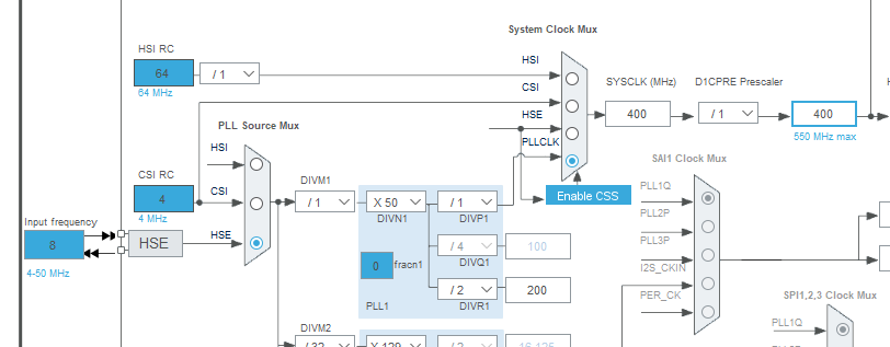
The main clock source is HSE (external 8 MHz resonator) to the PLL which generates a 400 MHz SYSCLK.
So much for code generated by STM32CubeIDE that actually worked and blinked an LED. Focus was on linker script and startup, so I left out the actual blinky stuff.
Discussions
Become a Hackaday.io Member
Create an account to leave a comment. Already have an account? Log In.