Until now we made the QFM (quartz fork) module and we used signal generator to create a sine waveform with specific frequency and measure the output using scope.
Now we want to do it programatically. We would like to have a device that will gnenerate frequency as a command from Arduino board and meassure the output using Arduino.
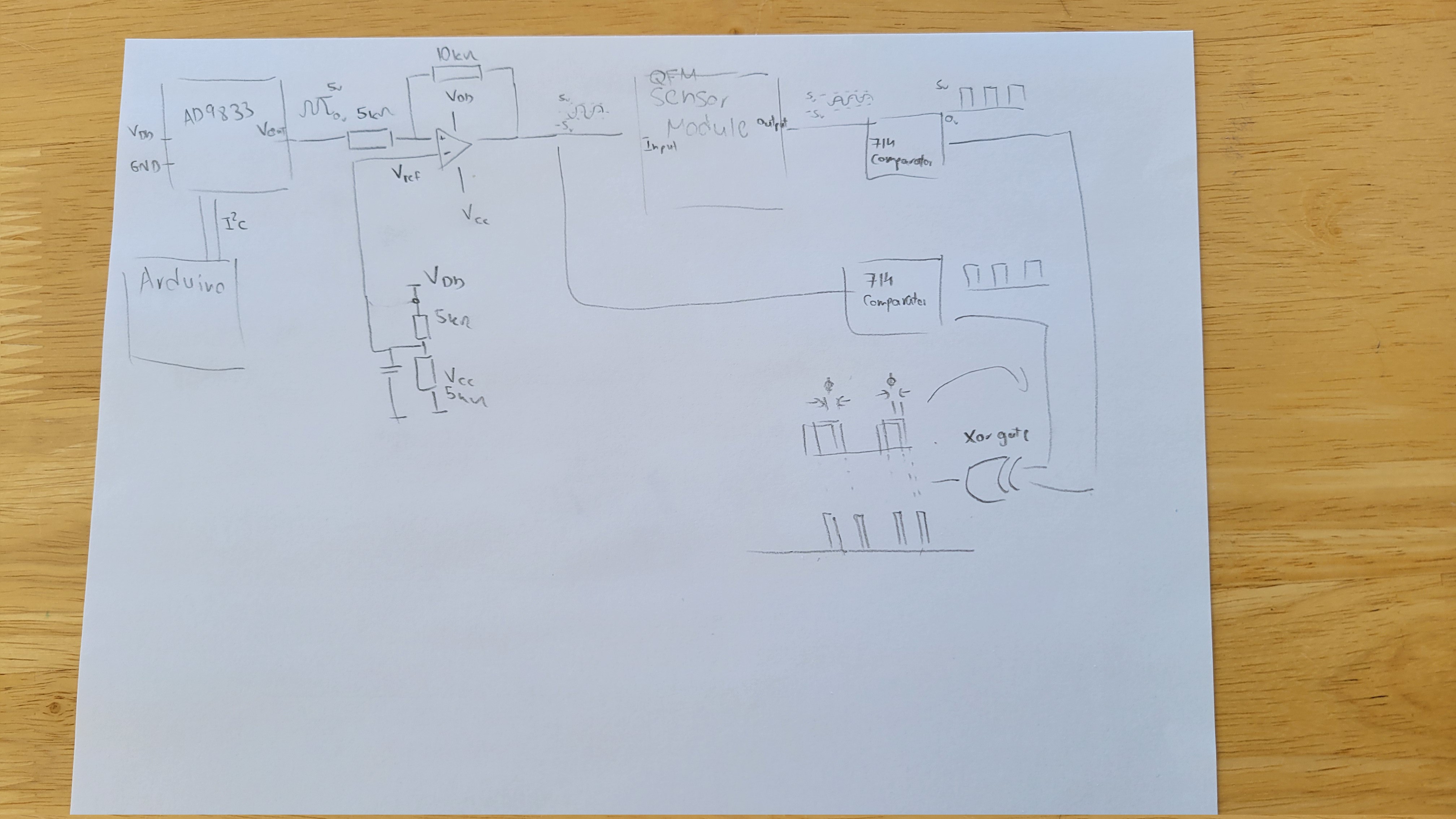
To create a signal we will use AD9833 signal generator board. (For now as a external PCB board with few capacitors and crystal clock). AD9833 can output frequency with 0.1Hz precision. Arduino can provide I2C that will set AD9833 to the desired frequency. For output we wil look for zero phase as this is less error prone (at least it's looks for me now).
The next step would be to add xor and integrator to find the phase difference.
For now we can see it how it changes.
Now, I've added two comarators and XOR gate and got nice two peaks for each half cycle as expected.
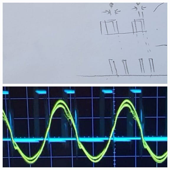
Now we get digital output of the peaks. Since output is digital we can simply sum the time output is high relative to low. The frequency where it's most low is the main frequency.
The last part would be a converter of AD9833 which output is 5-0v to voltage needed by QFM module which is 5-(-5)v.
-----+-------------+------------+--------
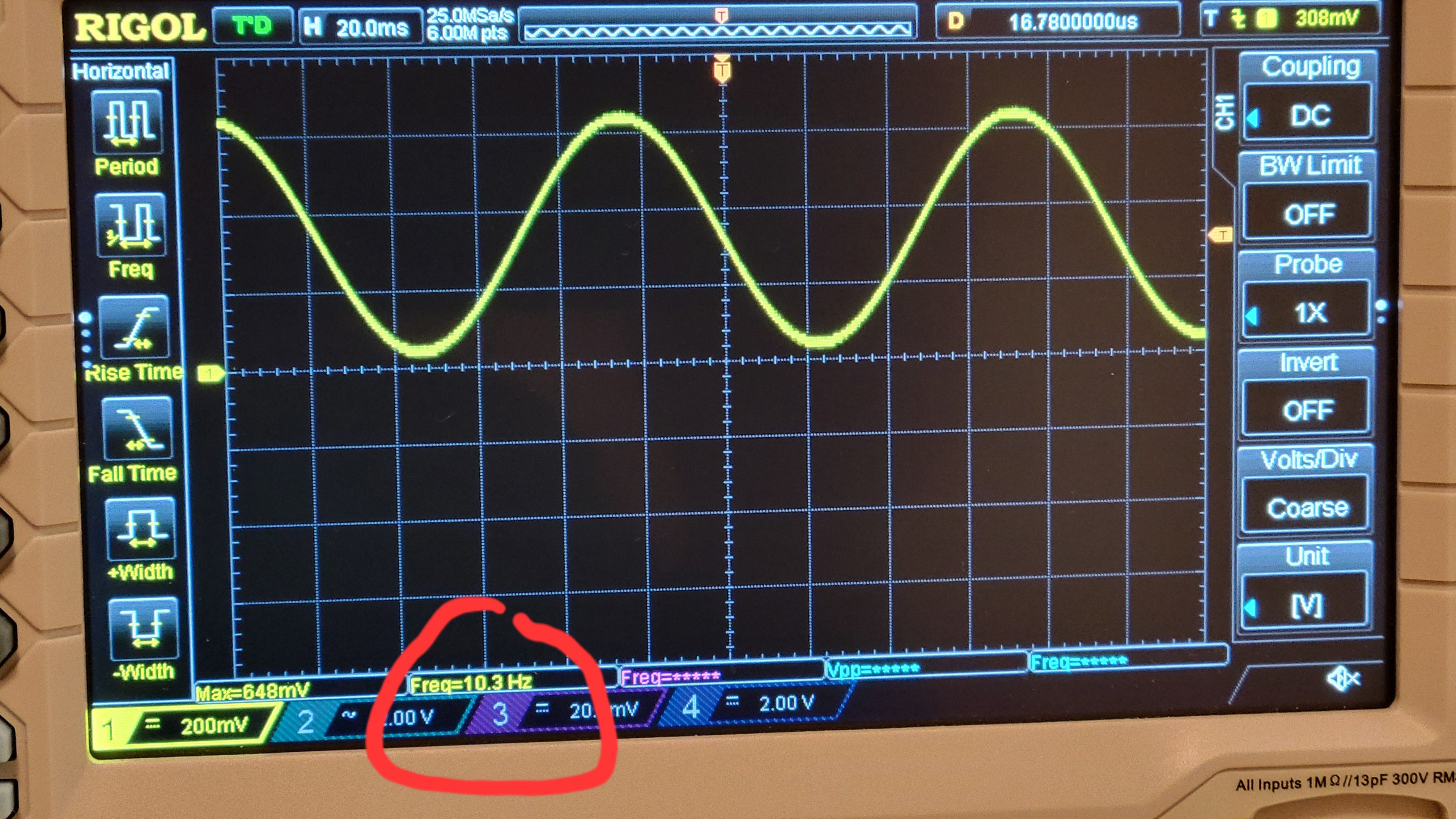
Ok, got AD9833 connected and running. The amazing thing I didn't know previously is that it can get float numbers which means we can set frequency of sub Hertz. For example here I've set 10.3Hz
The last part will the LM324 op amp to convert 0.6v of AD9833 to 5-(-5) volts swing that will be input to QFM.
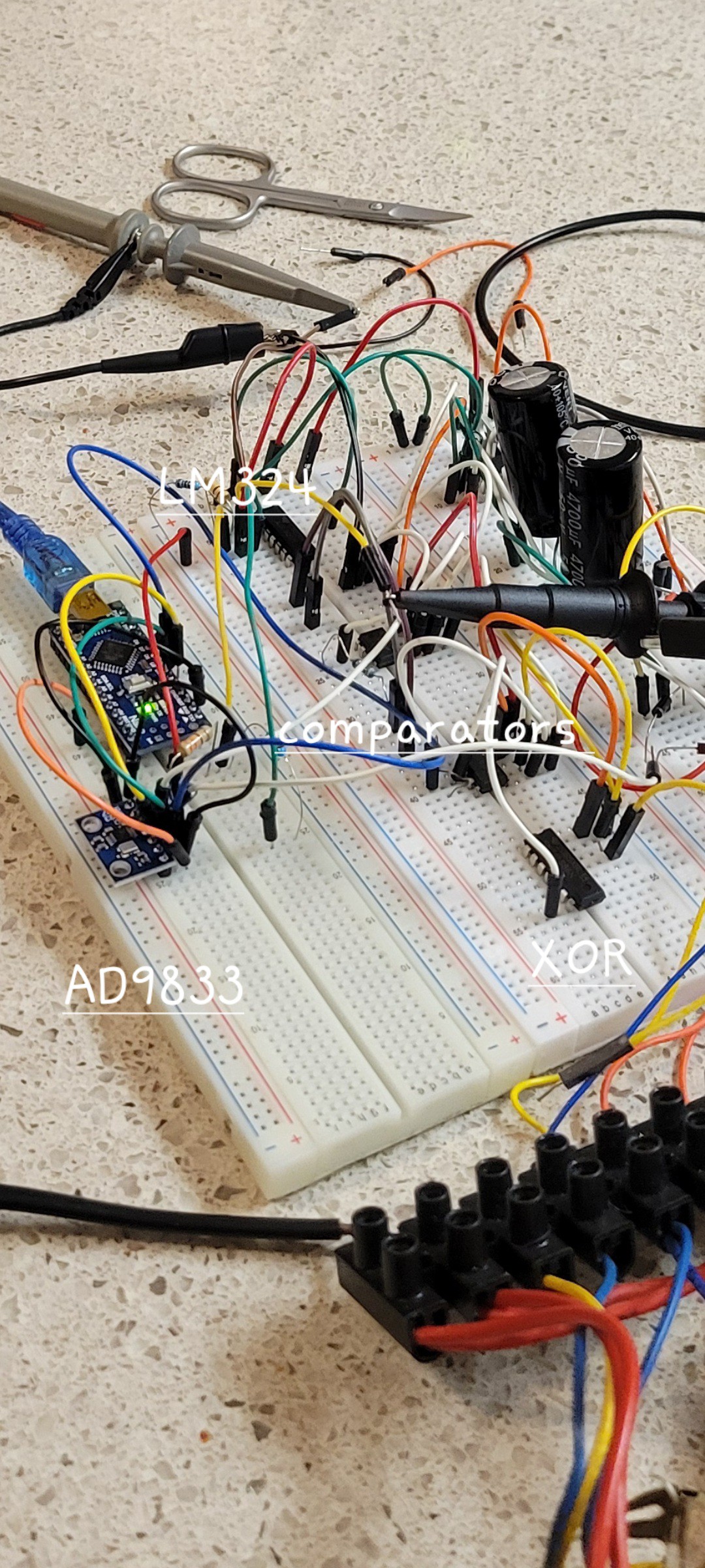
Ok, got all components together working...
The output is bit warped but I think good enough to me. (It should be sine but it looks like triangle)
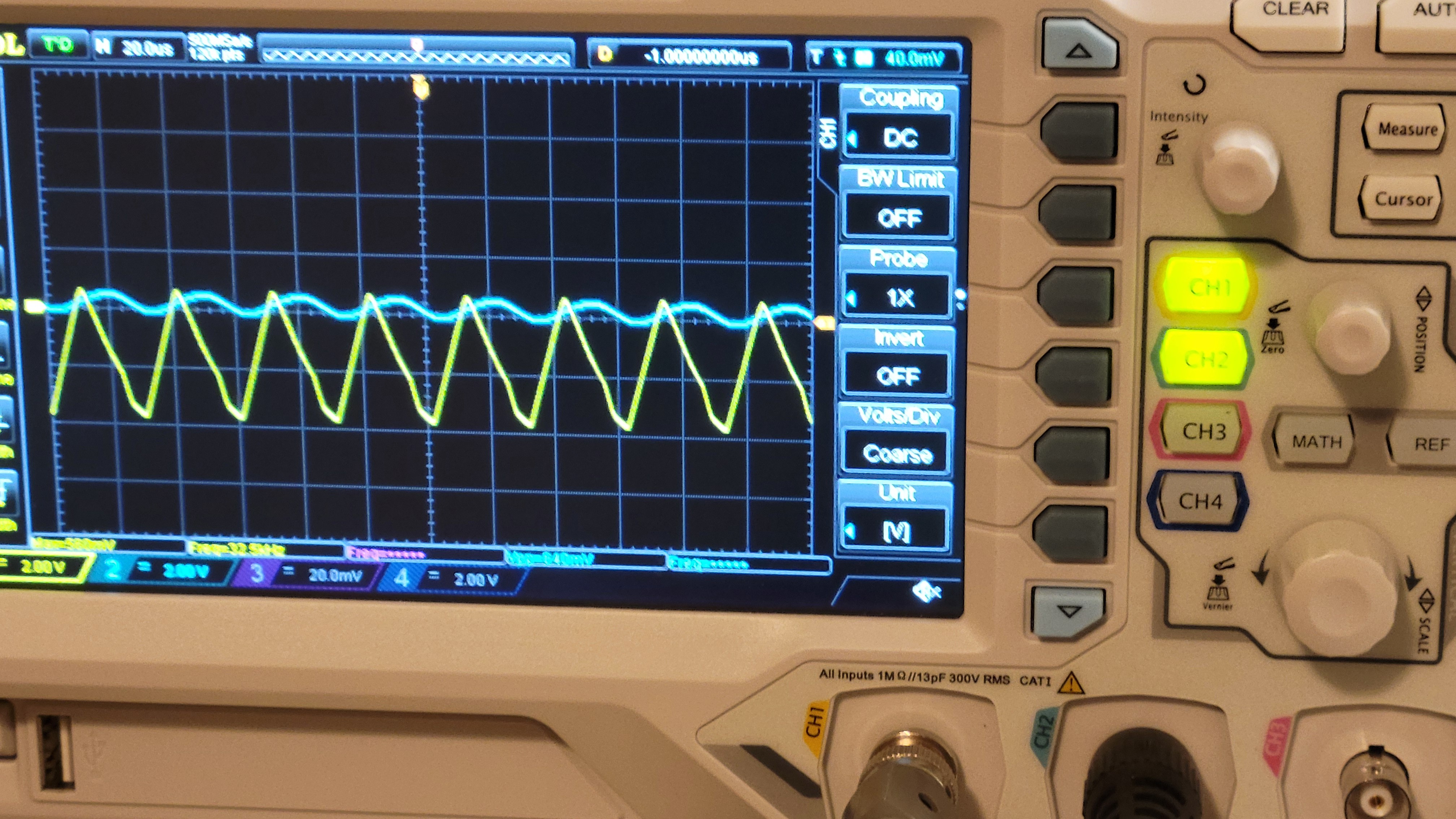
That's all for the electronic part.
Next stage would be to put them on PCBs. Working on breadboard is not convenient
After adding some twicks, I got this out.
When signal alighn (no phase difference) you got almost zero
Now, same setup, different frequency and you got
------------- UPDATE -----------------
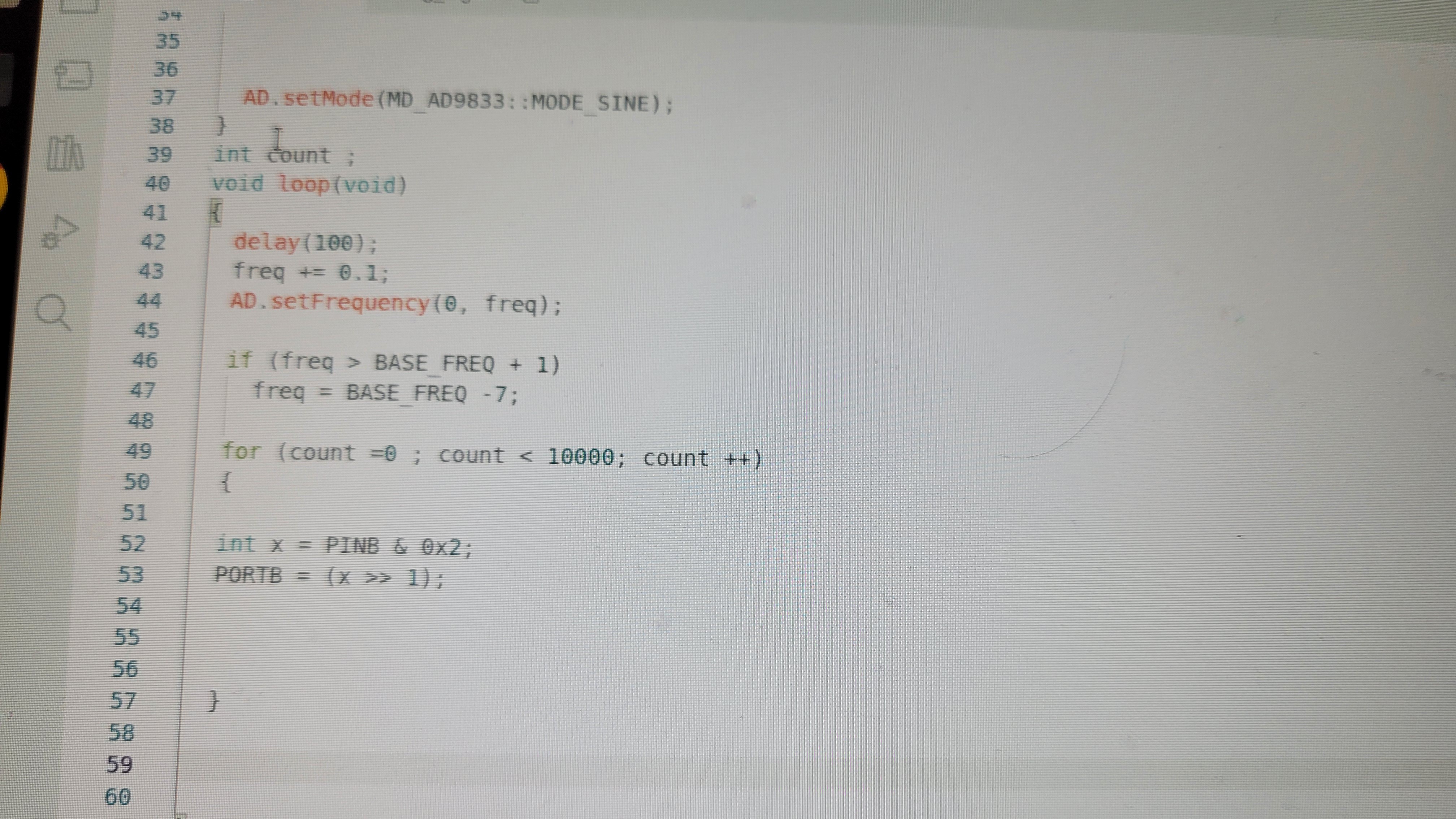
I felt I had to check all the way from clock generator to Arduino. Especially the connection between XOR gate to Arduino. So I've made simple Arduino program that simulates it's input. It's output high when input is high and low in the other case. The result was surprising, simpleReadPin and writePin was too slow. With such low resolution of 5 micro seconds Arduino could not differentiate between match and mismatch. For me it was OMG moment since changing Arduino to FPGA means serious delay. Luckily I know it's only implementation issue. Arduino runs on 16MHz clock and output read/write are two clocks. Which leaves enough time to be sub micro second measurement.
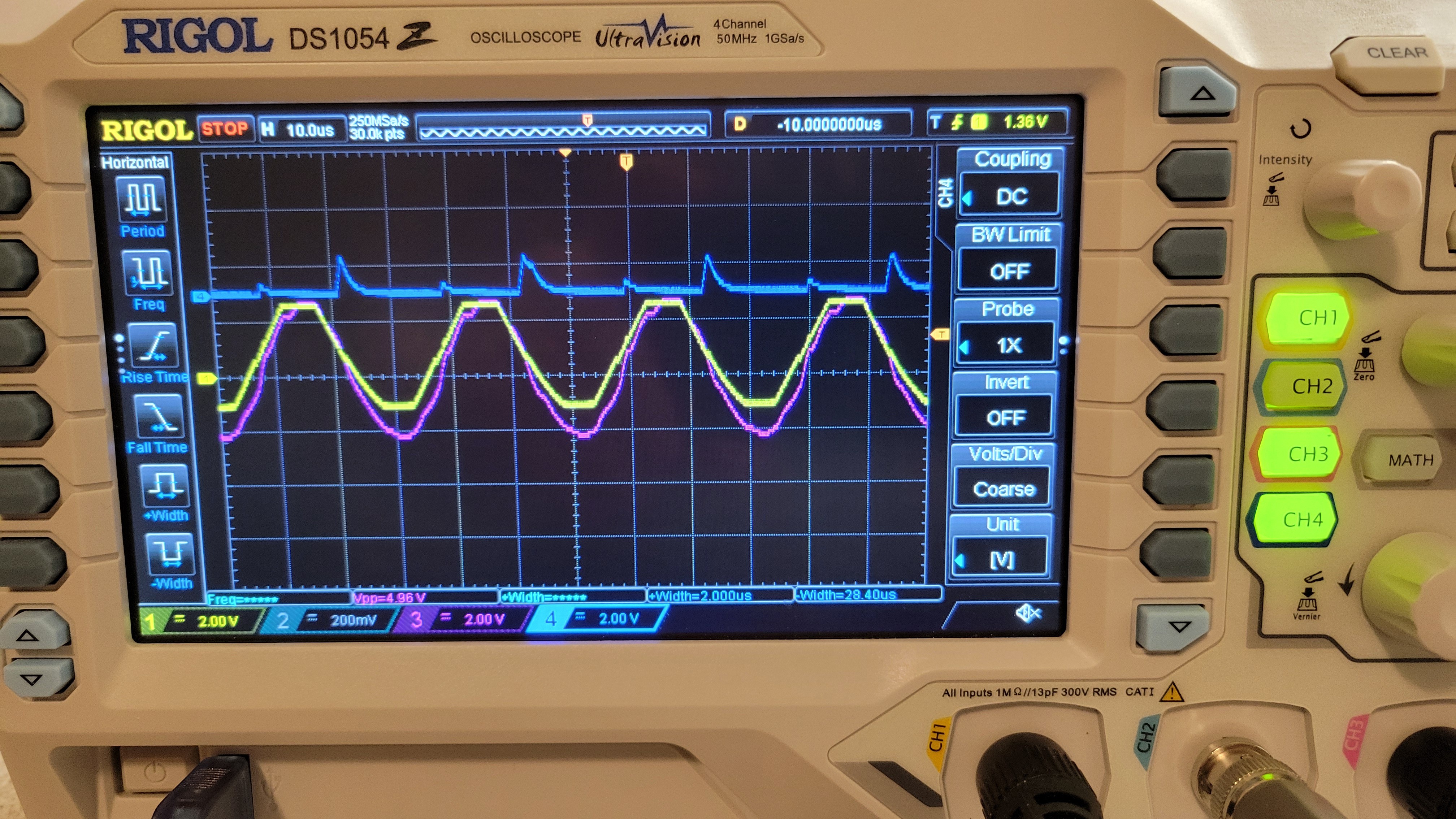
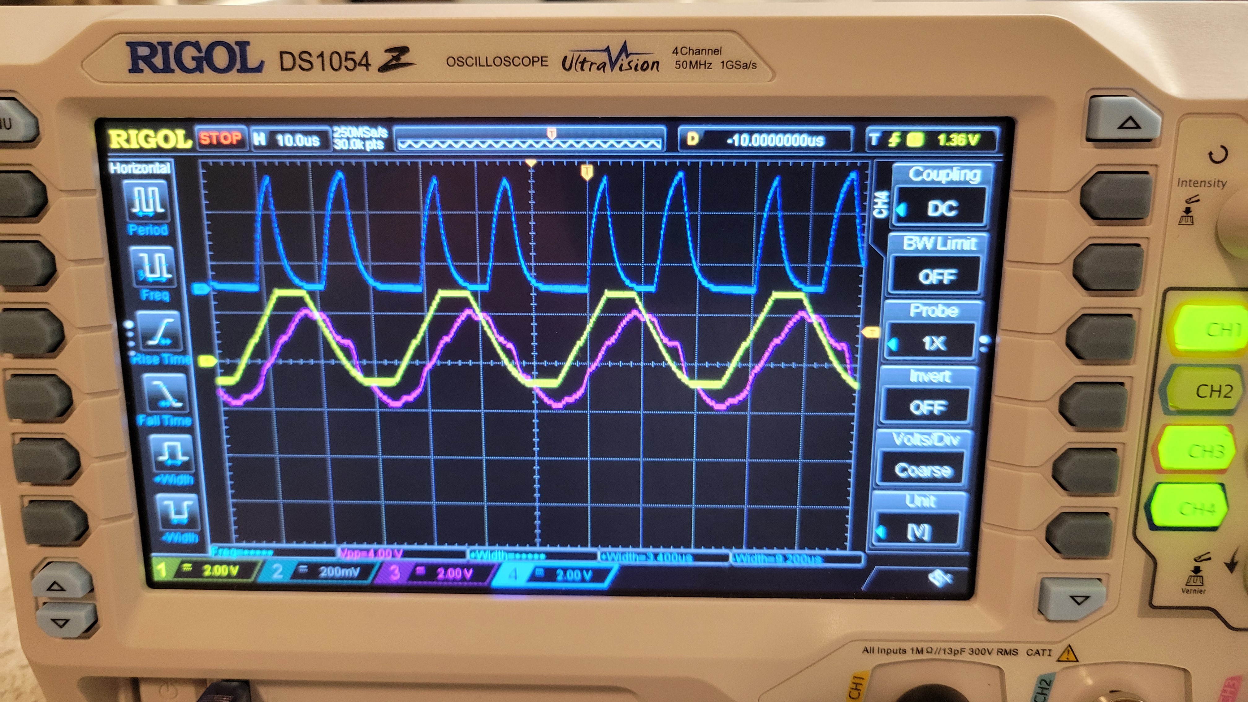
So going to assembly level with PORTB and PINB commands
Gives us nice results of
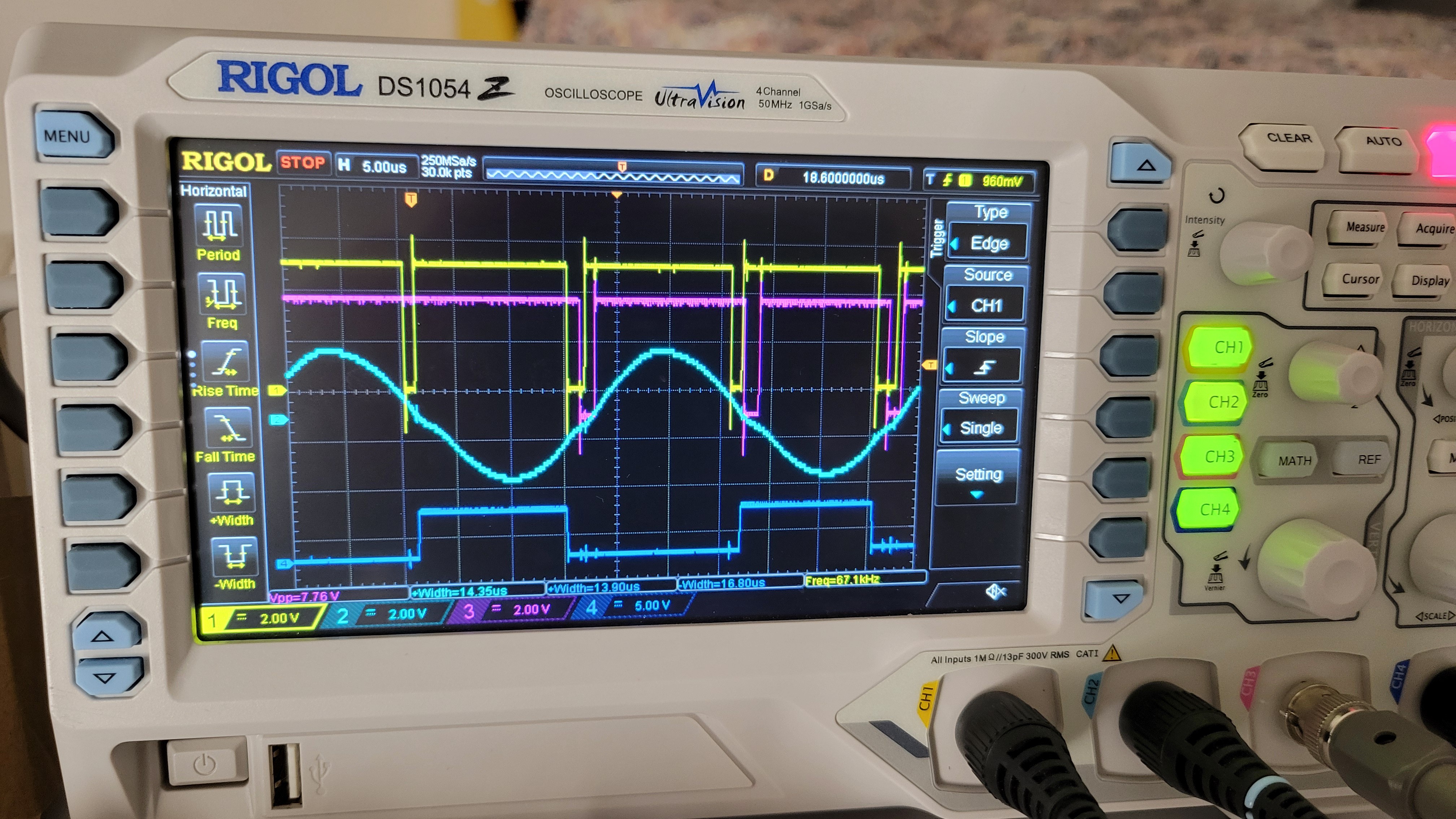
The yellow is XOR gate output and pink one is Arduino output. We can see that Arduino is following most of the changes. (Actually the real measurements would be faster since instead of PORTB command it, of two cycles, it will be simple add command of one cycle.) Anyways, it's good enough and we can continue to building PCBs reassured that electronic part is working and communicating with Arduino level correctly.
Discussions
Become a Hackaday.io Member
Create an account to leave a comment. Already have an account? Log In.