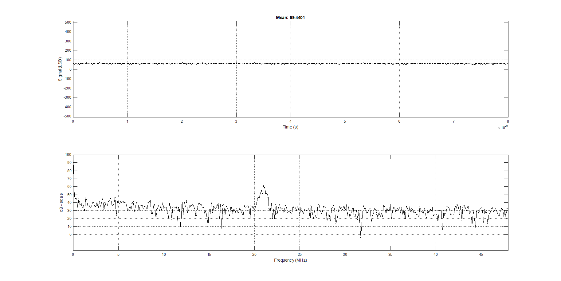
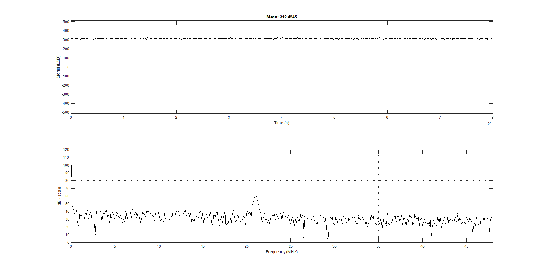
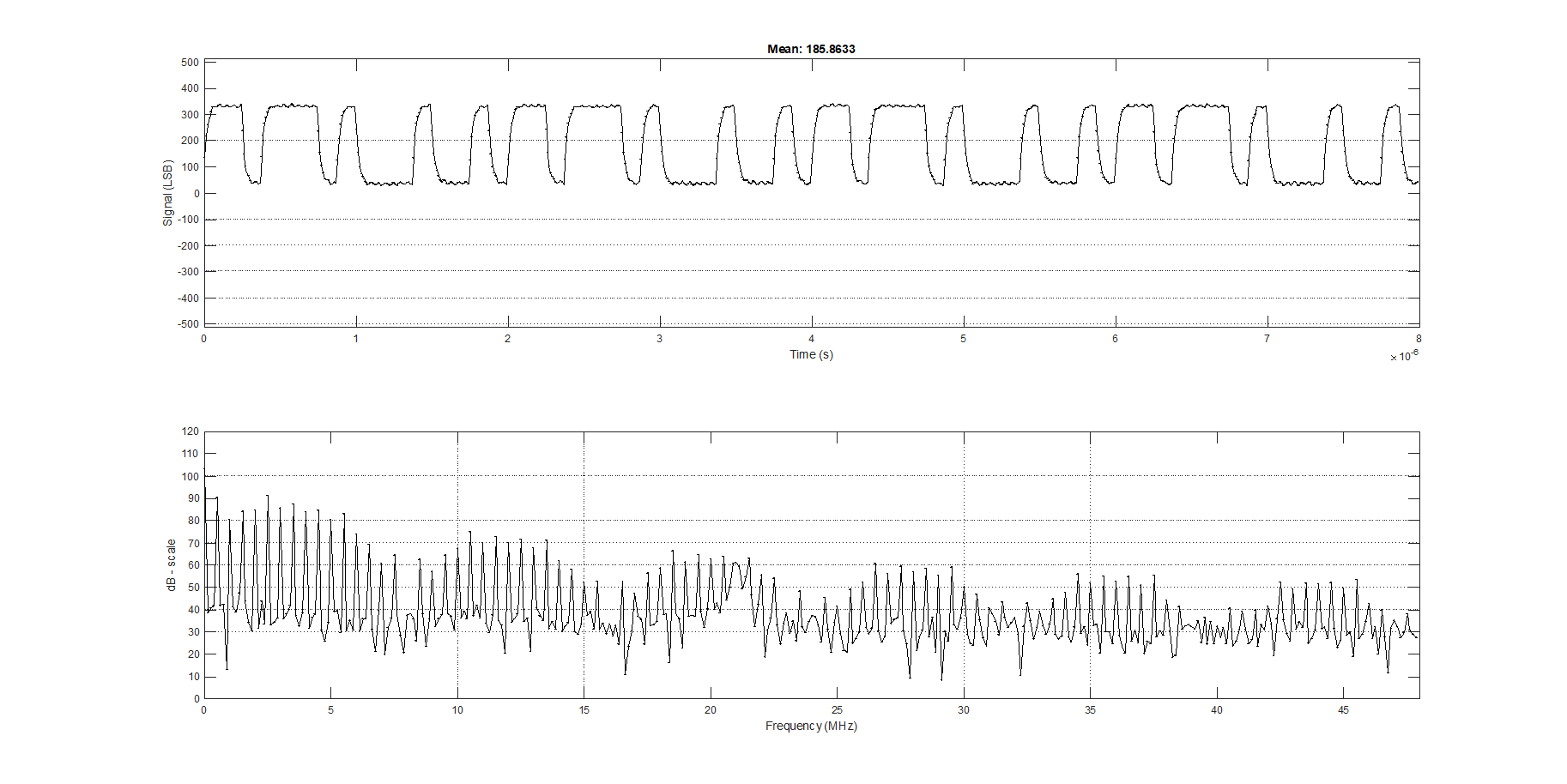
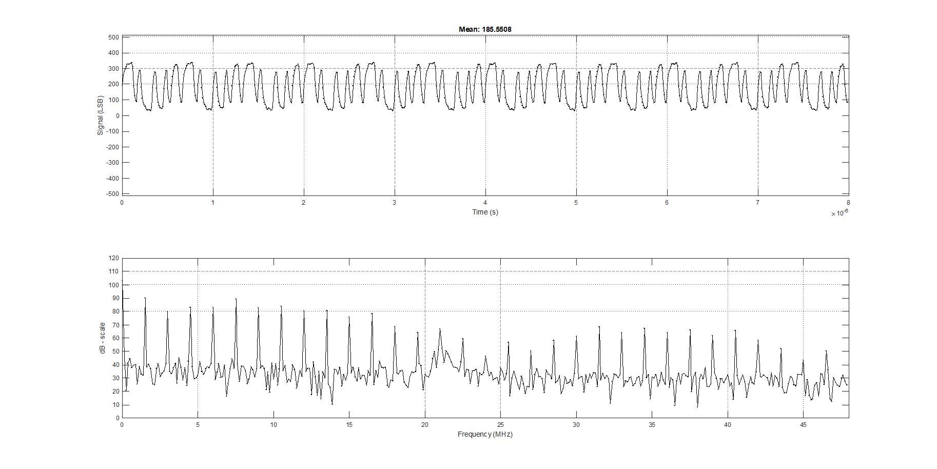
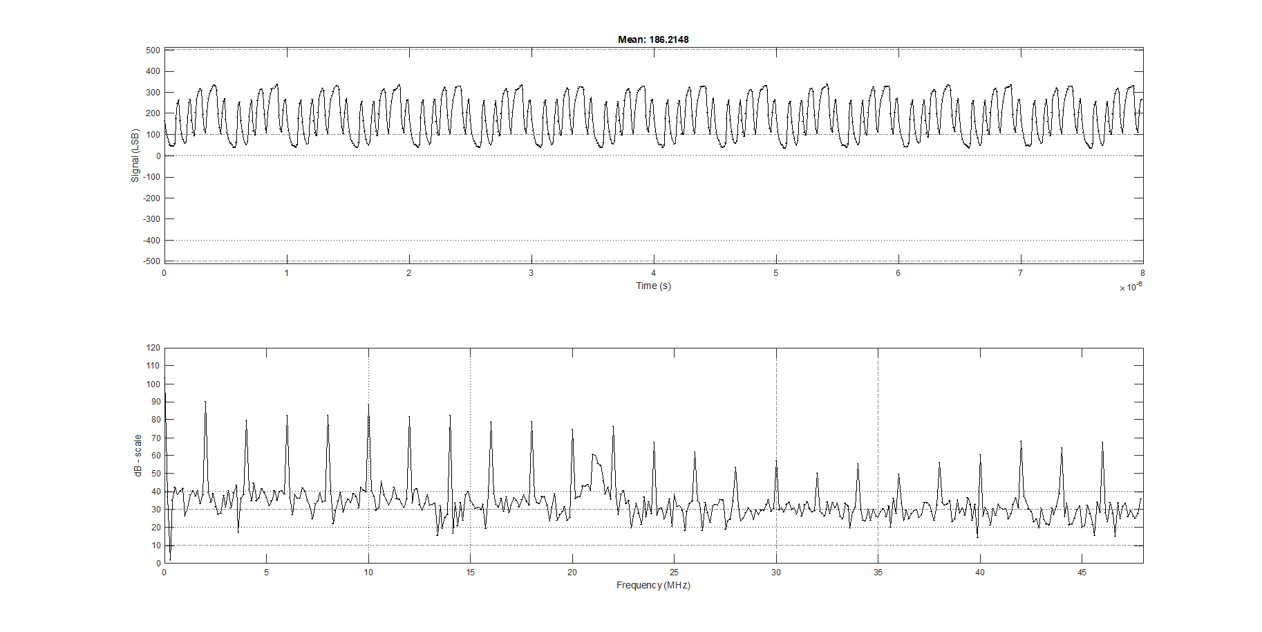
I wanted to build a very simple oscilloscope using the raspberry pi pico. The input stage is very simple - no changing scaling, no trigger, just grabs the samples from the ADC10080 and saves them. Then, you can post process.
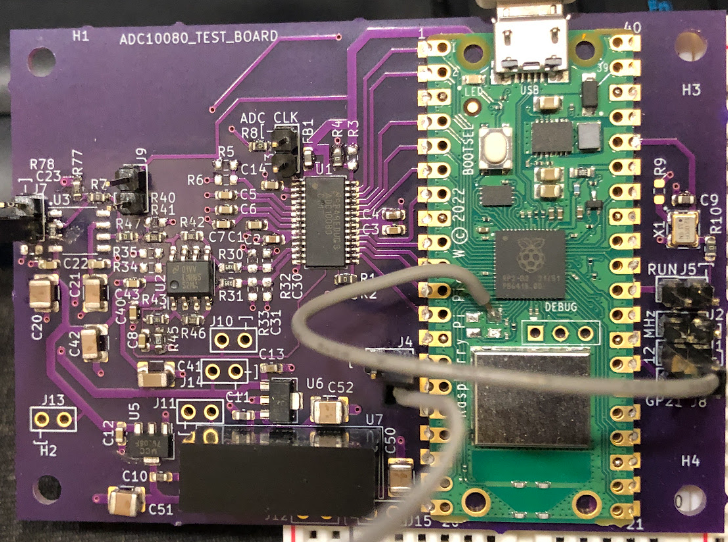
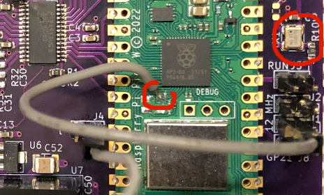
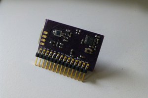
Here is the circuit board. First thing - I treated the raspberry pico W as a surface mount component, so it is mounted directly on the pcb I made. Second thing - there is only one high speed op-amp. The input resistor was set to 100 k, and I wanted about ~300 LSB when the input voltage was 3.3 V.
Here is the schematic for the op-amp lifted from the LMH6552 datasheet:
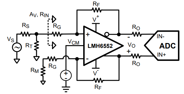
In this case, RS is 100k, RT is 20k, RG is 15 k, RF is 20k, and RM comes out as 16.666 k (16 k is what I had on-hand), so the circuit is a touch imbalanced. The value of RF is a touch high, so it probably hurts the noise and bandwidth a bit. For the datasheet, please see LMH6552 datasheet. I had originally placed a first opamp in the input path, but realized it wasn't needed.
The opamp needs +/- 6 V, so I used a +/- 9 V supply (the large black brick at the bottom), and then used linear regulators to get +/- 6 V. The ADC10080 has a common mode voltage source, so that is connected to the LMH6552.
I ran the statemachine for the ADC10080 at 192 MHz (i.e., 12 MHz x 16). Integer clock rates seem to give better jitter out of the raspberry pi pico. Since the code generates the clock with the "sideset", and then samples on the low part of the clock, this gives 96 MSps (yes, a touch fast for the ADC10080).

 doctek
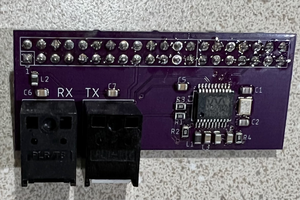
 Nick Sayer
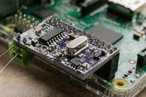
 Bud Bennett
You are welcome. All of the code is on github. If you need anything, please let me know.