The first step in order to build one is to get some plans, or make some plans. As I've not seen any available plans for a stock ticker, this project is to document my efforts to create plans for a stock ticker, and maybe even building one.
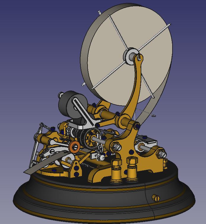
Unfortunately there is no example of a ticker near me so I have been forced to do my reverse engineering from online photos and old patent drawings. Fortunately there are quite a few very nice photos available from the tickers that went on auction over the years. After studying the photos and researching the various patents I have a pretty good understanding of how the ticker functioned. Using that understanding, the photos and some educated guess work has allowed me to create a 3D model of a ticker in FreeCAD.
I figured out most of how the tickers worked and how they were adjusted (most but not all, but I will get to that in a little bit). The adjustments built in to the tickers is very extensive. There are adjustments for striker travel (both up and down limits), paper travel stop position, magnetic coil gaps, and capstans for adjusting spring tension for both the magnetic return strokes.

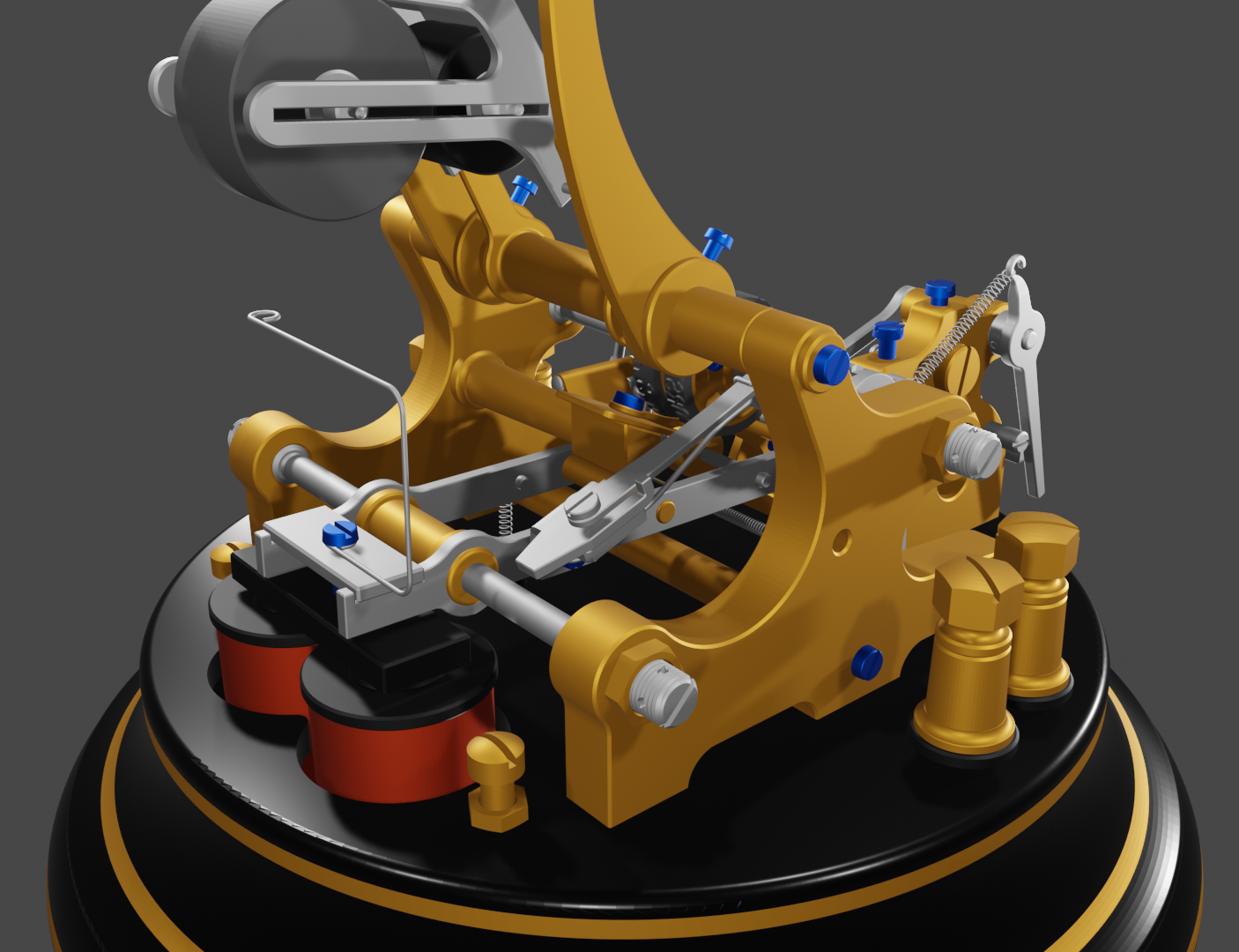

There is also adjustments for the reset/sync stop. The addition of the sync stop arm and its associated screw is a beautiful bit of engineering. In simple terms it allows the various ticker connected to the same loop to be synchronized by the simple expedient of advancing the letter and number wheel ratchet more than approximately 75 steps (2 1/2 full turns) with out striking a character.

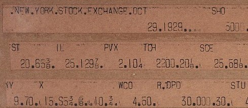
The letter and number wheels required quite a bit of work. I ended up recreating the font in order to get the characters sizes and glyphs just right. The required characters for the number wheel are a bit of a guess as I was not able to find a complete character list. So I based the wheel on preserved ticker tapes from the 1929 stock market crash. More on that in a bit.

Another neat innovation of the tickers is the mechanism to switch which character wheel is struck by the hammer wheel on the striker. The mechanism uses pins in the character wheel axle. The pins are located at specific positions so that the act of striking character at that location will force the "manta" rocker to pivot to one side or the other. Pivoting the rocker will shift the hammer wheel to be below one or the other character wheel. The pins provide 2 opportunities per revolution to select either character wheel. Working out the dimensions for the manta rocker and the pins was a fun little challenge.
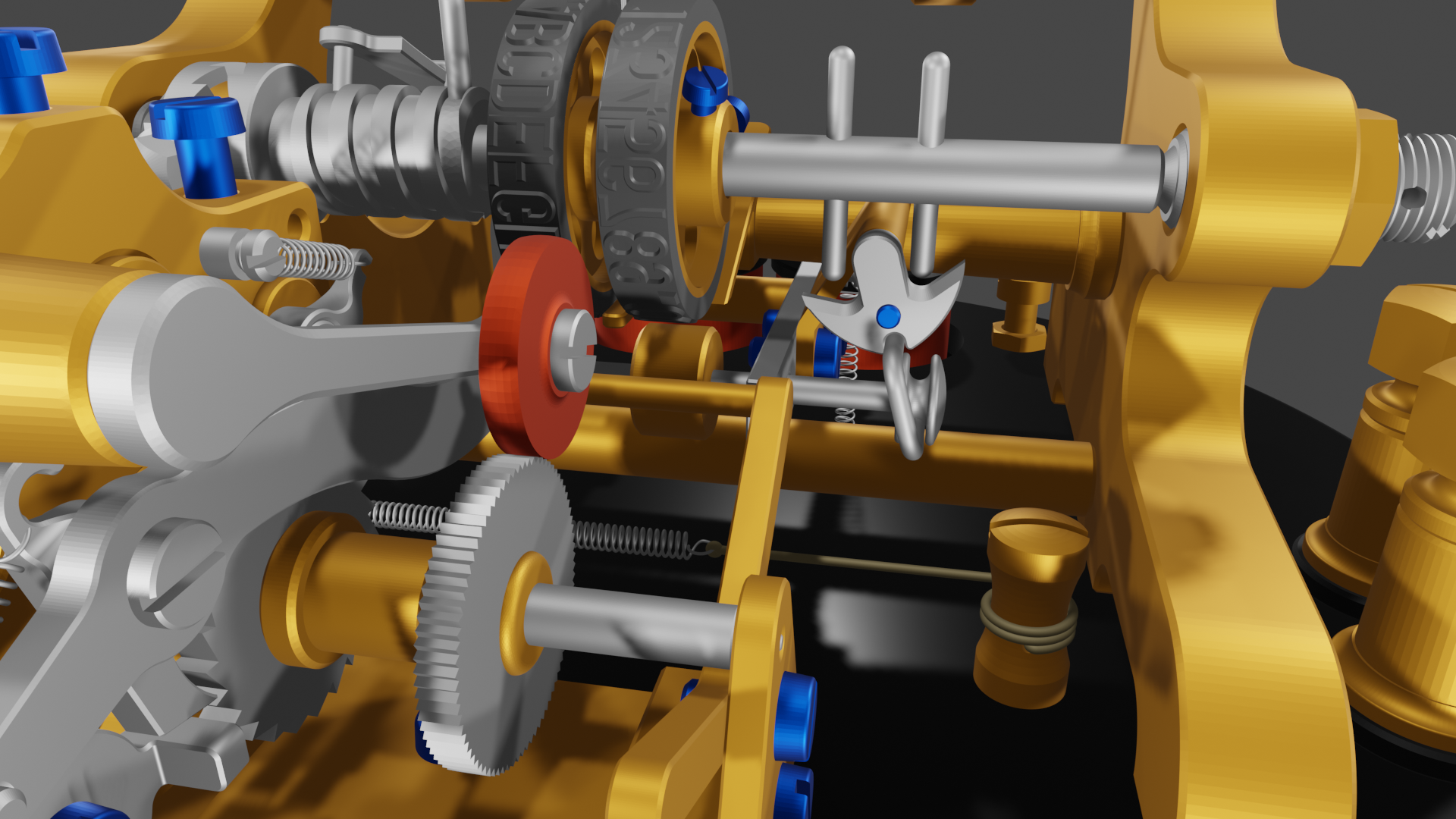
And now come one of my quandaries. As I understand the mechanism I could setup the rocker so that hammer is shifted back and forth without striking a character and not advancing the paper, or it will strike the character selected on the target wheel (which from the pictures that I found is a small square on both wheels) and advance the paper.

That means that selecting a wheel will either always print the square on the selected wheel, or that the square on the letter wheel will never be printed as the square is only located at the positions that will select the letter wheel.
The problem I have is that the exemplar ticker tape from 1929 shows both squares printed from the letter wheel and transitions from letter to number wheel and back without a square being printed and without advancing the paper. So I must be missing something and I'm hoping someone out there can enlighten me as to what that is. (I found source image for the following at the "Museum of American Finance")
Another question that I have is with regards to the pivot screw for the letter/number wheels, striker and the character advance ratchet drive arm. From the pictures that I found the it looks like the are convex and the axles are concaved, I would have expected it to be the other way around. Also there are two cross drilled holes in the slotted end of the screws which I think are for oiling the pivot joint. The fact that the holes seem to be drill completely through the screws would make...
Read more »


 Daren Schwenke
 Maximiliano Palay
 zapwizard
The 1920s Universal Stock Ticker revolutionized financial markets, paving the way for modern trading. Its impact echoes through history, shaping the way we perceive and engage with stocks. Today, https://meyka.com/ harnesses data analytics to empower traders with insightful analysis. Meyka stands as a beacon of innovation, offering a comprehensive toolset for navigating the complexities of stock trading in the digital age.