 Josh
JoshThe project is simple... but made to grow!
Overview
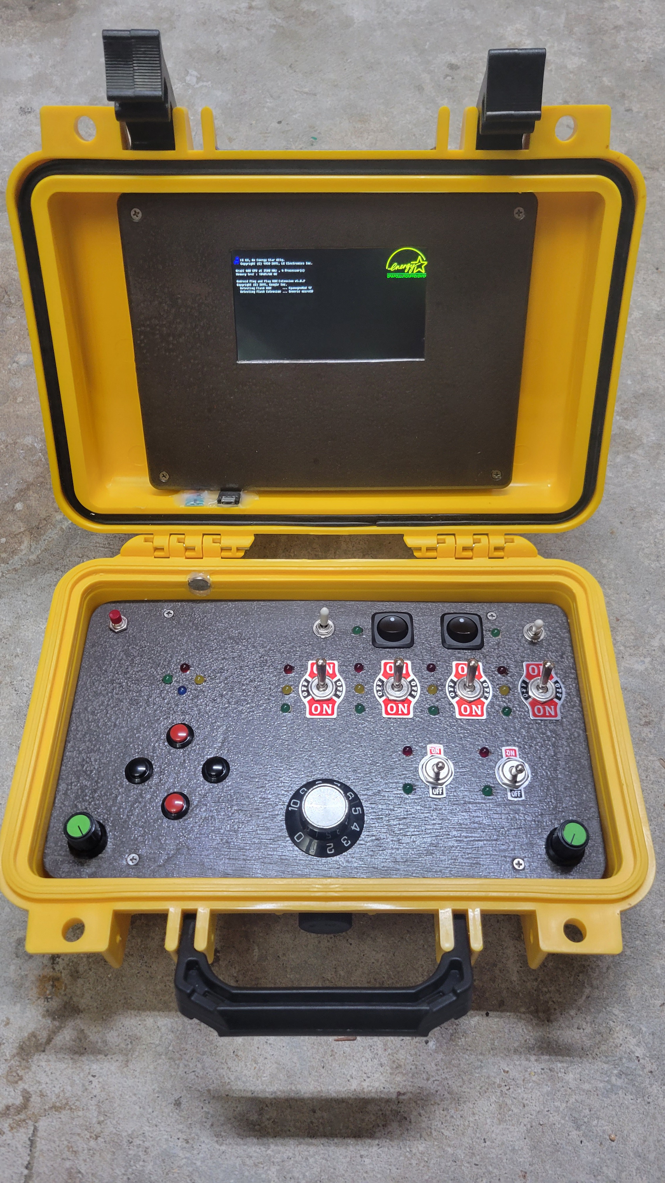
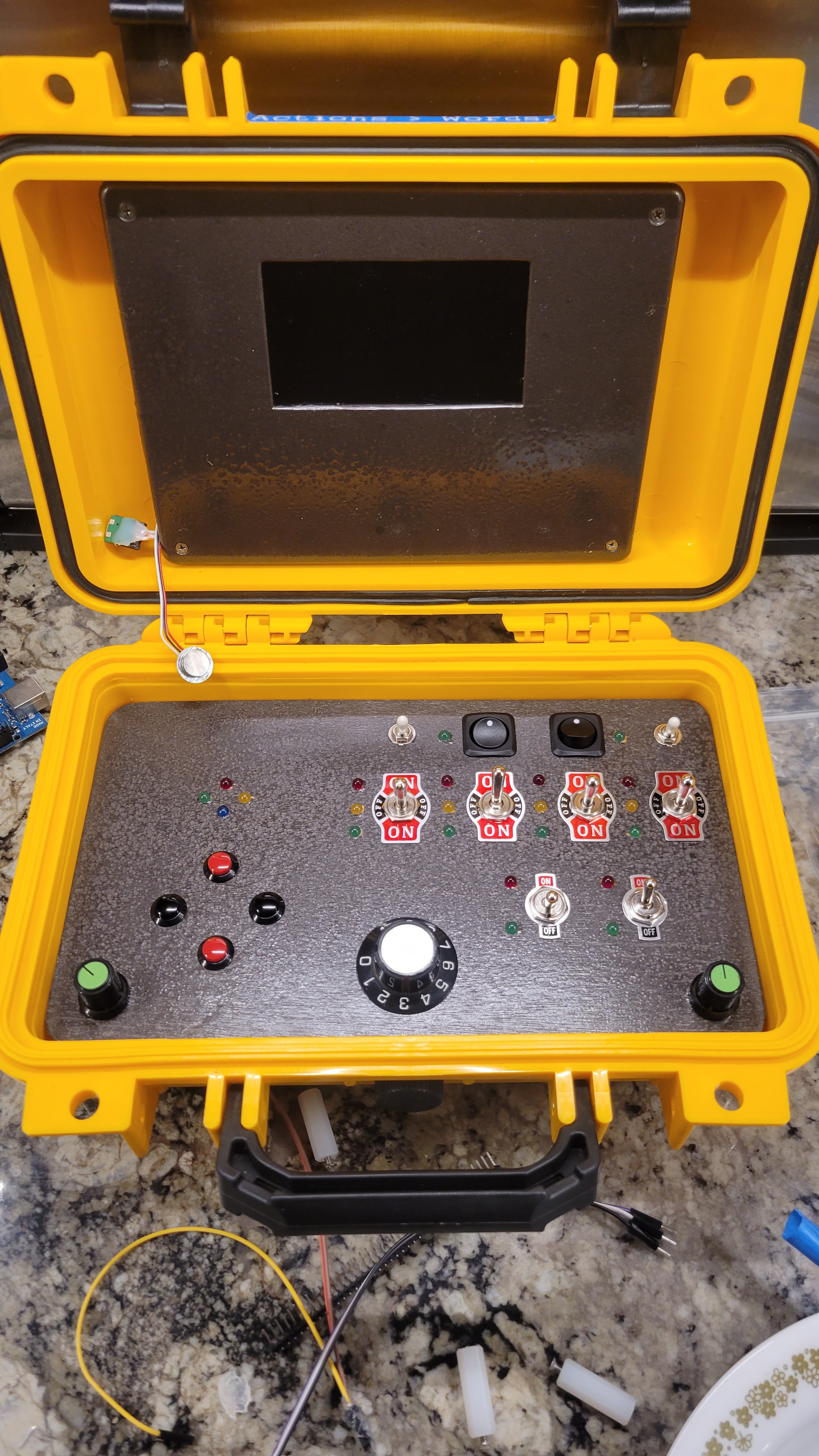
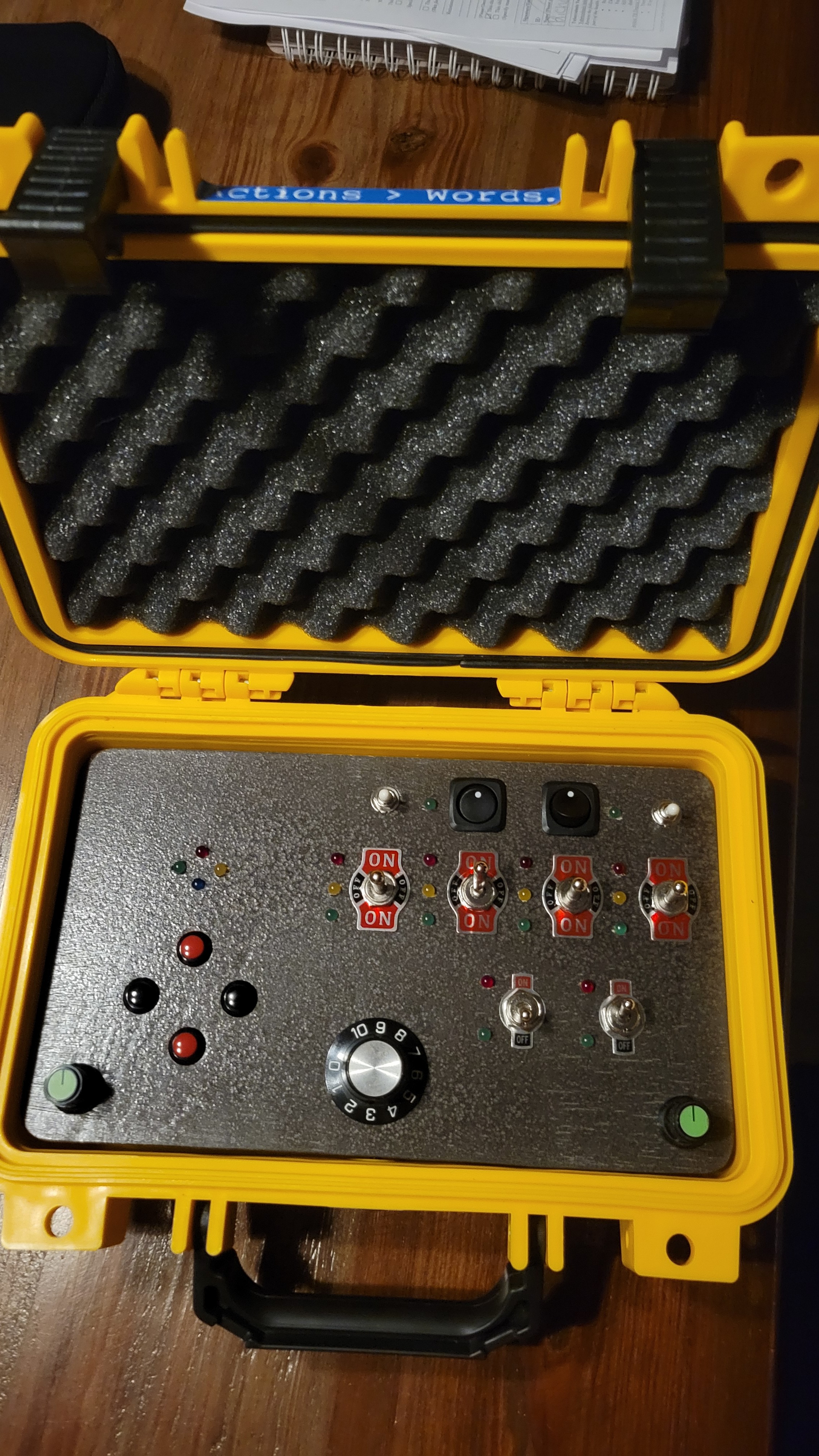
There are two main parts to this project: The lid is a simple media player "up-cycled" to be a foux-display for the "cyberdeck". The base is the real interactive portion, with switches, knobs, buttons and LEDs.

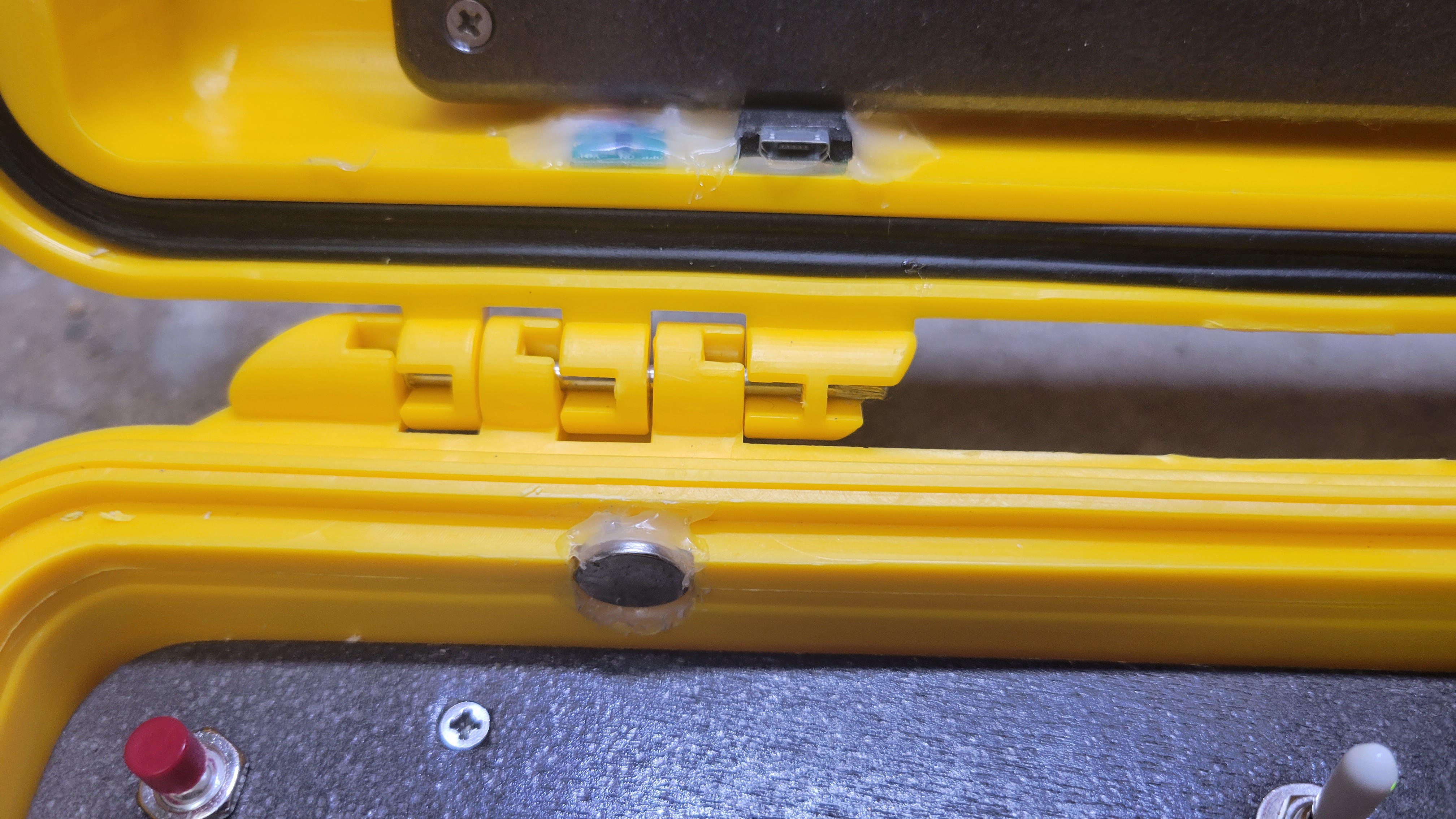
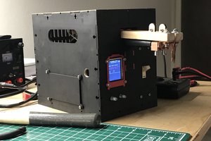
The Lid:
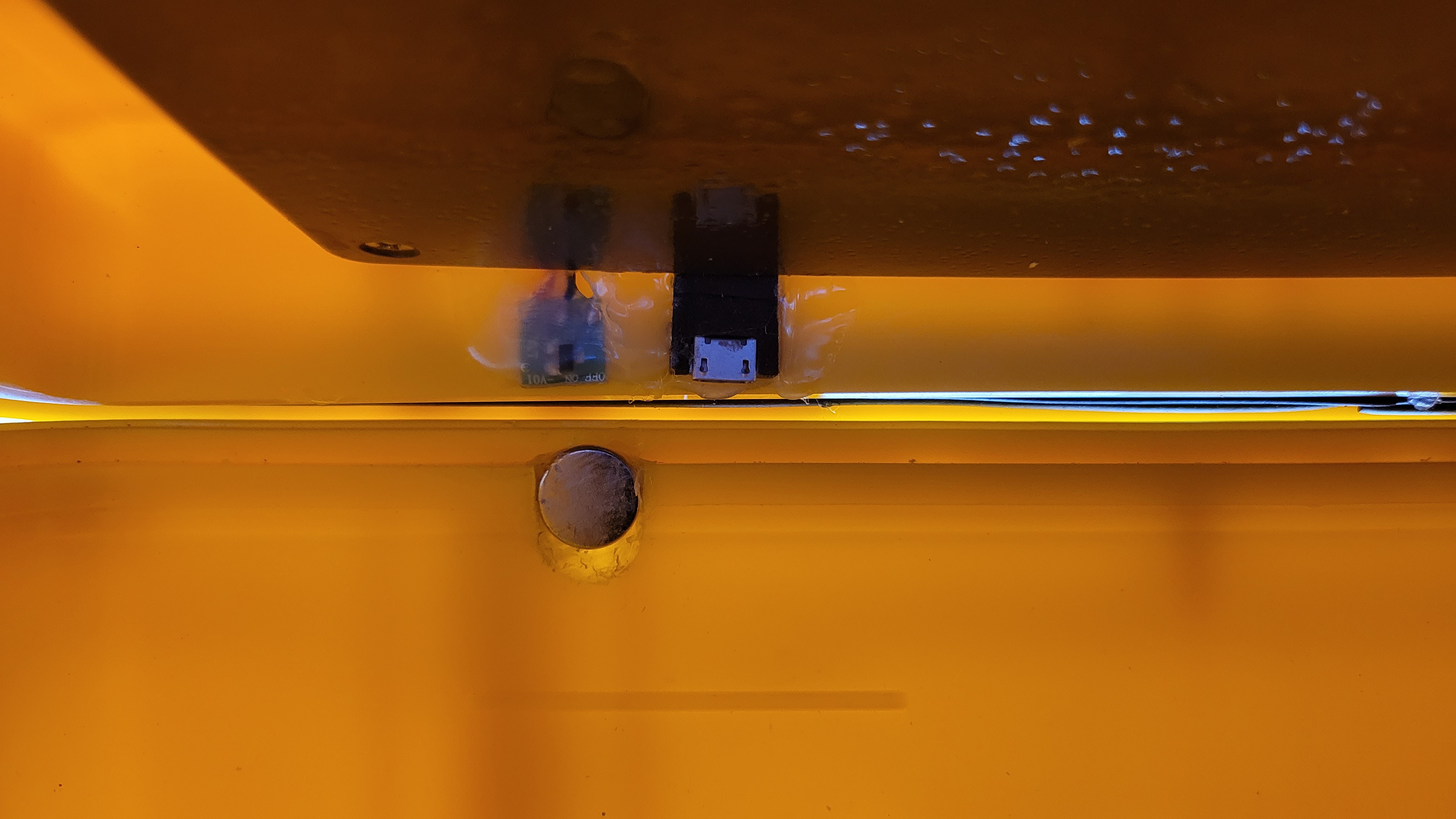
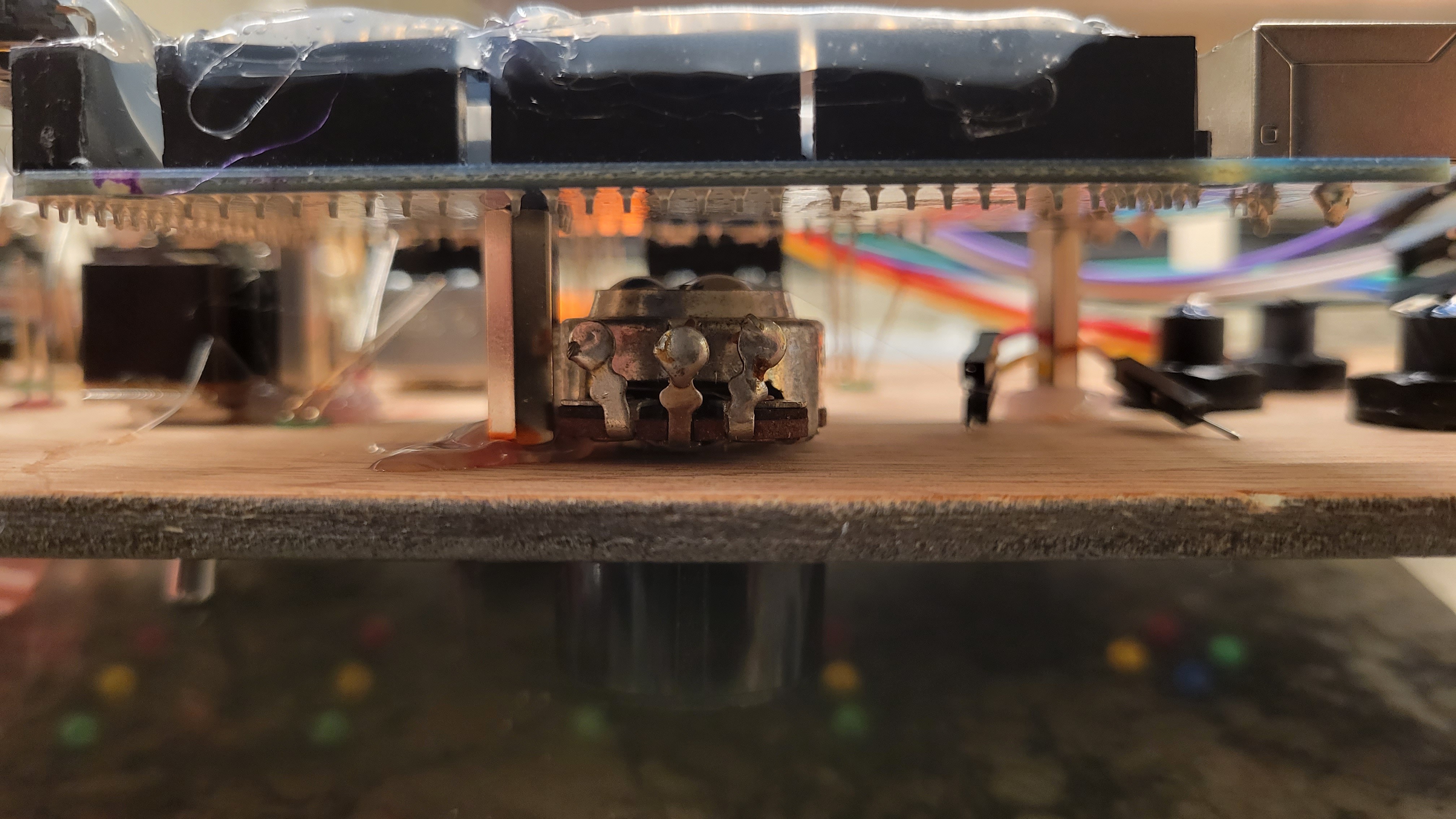
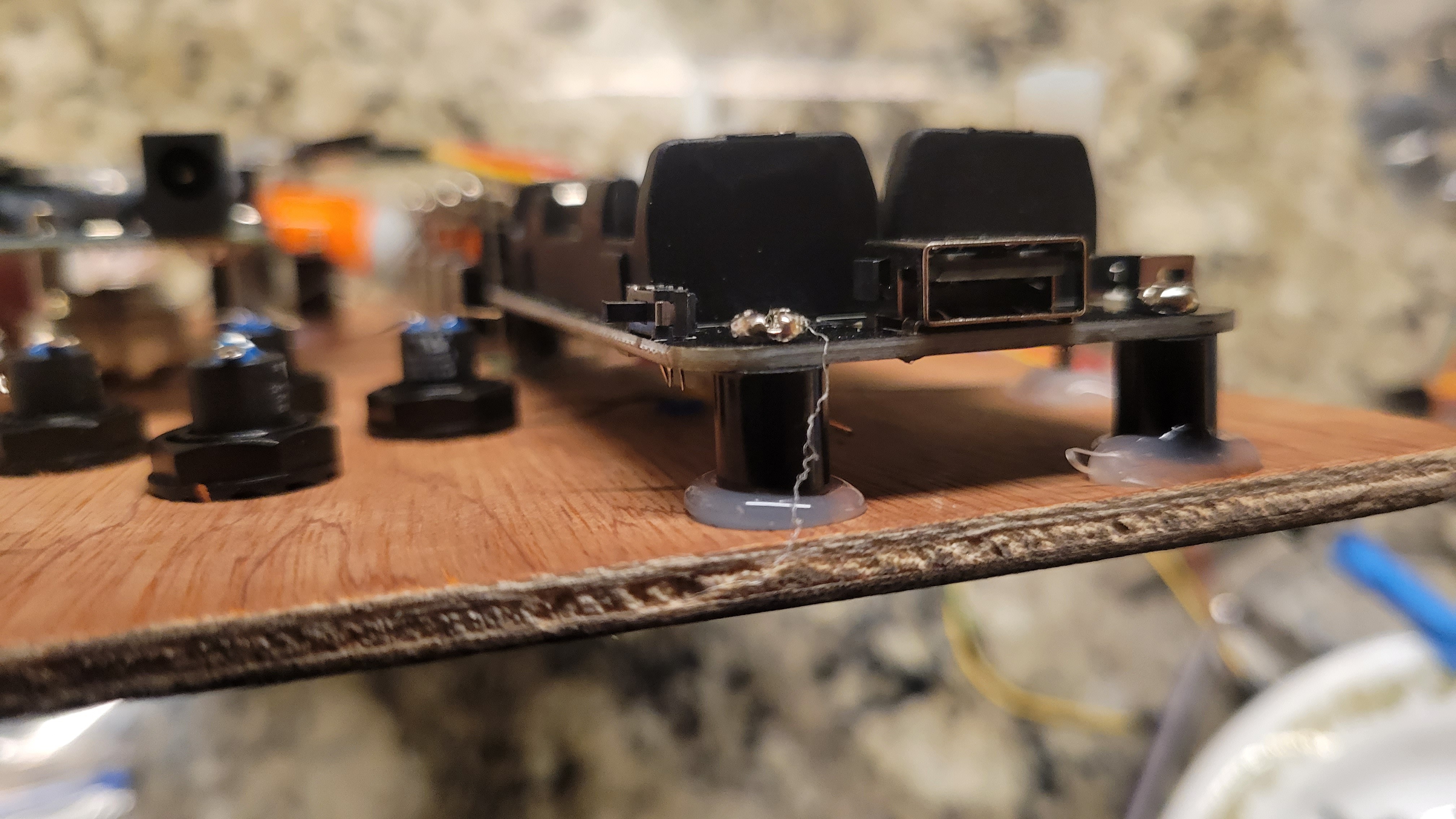
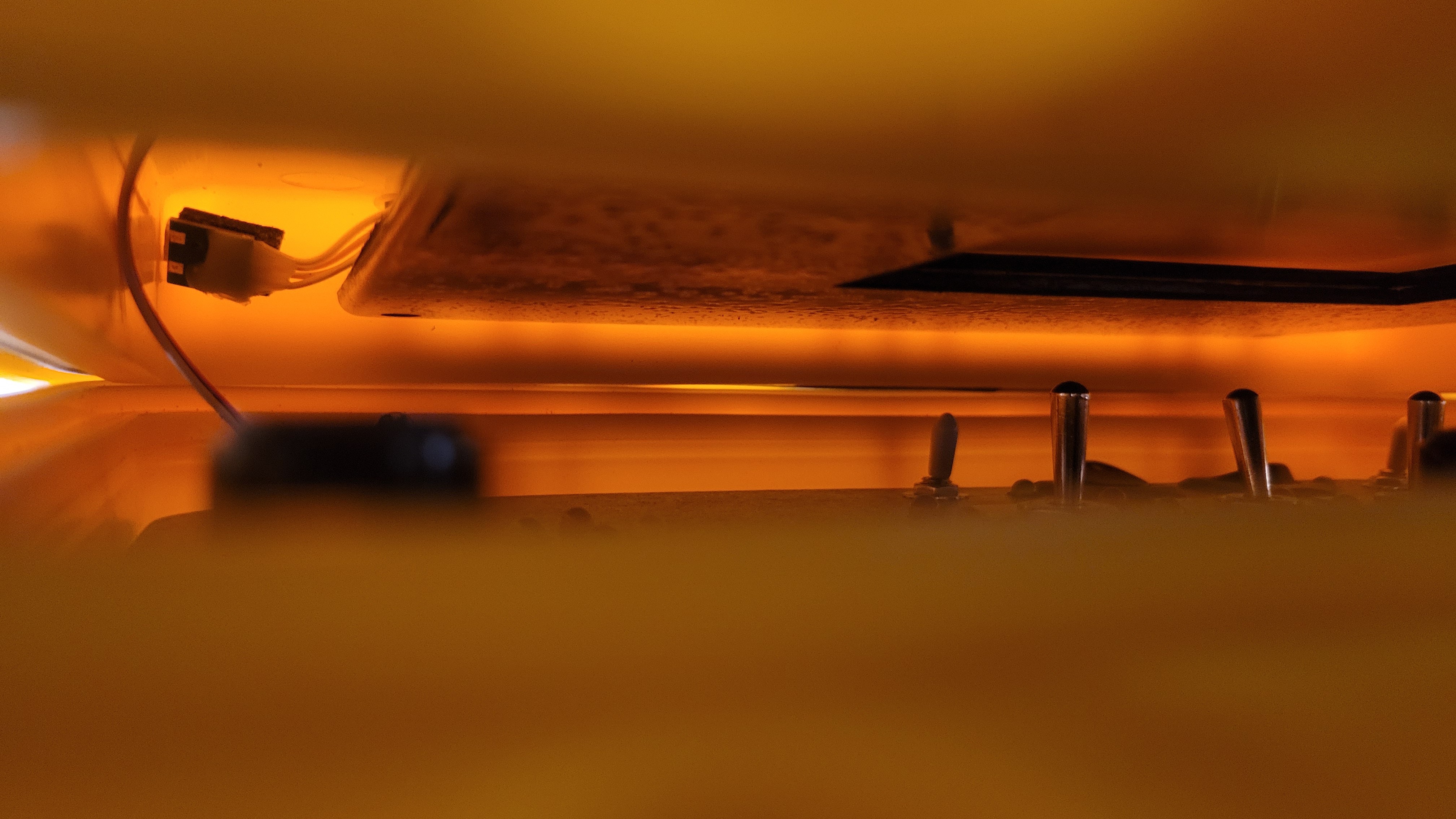
The lid contains the up-cycled guts of a video promotional card that I got in the mail. It's a V100-based SBC with 128M flash, low-res LCD, attached LIPO cell, and 3 buttons for play, next, and previous, as well as a magnetic sensor to turn it on when the lid is open and off when shut. The usb port is hot-glued next to the magnetic sensor at the bottom left in order to charge it and load different videos if I want. For now, the buttons are just hot-glued on the back and inaccessible.
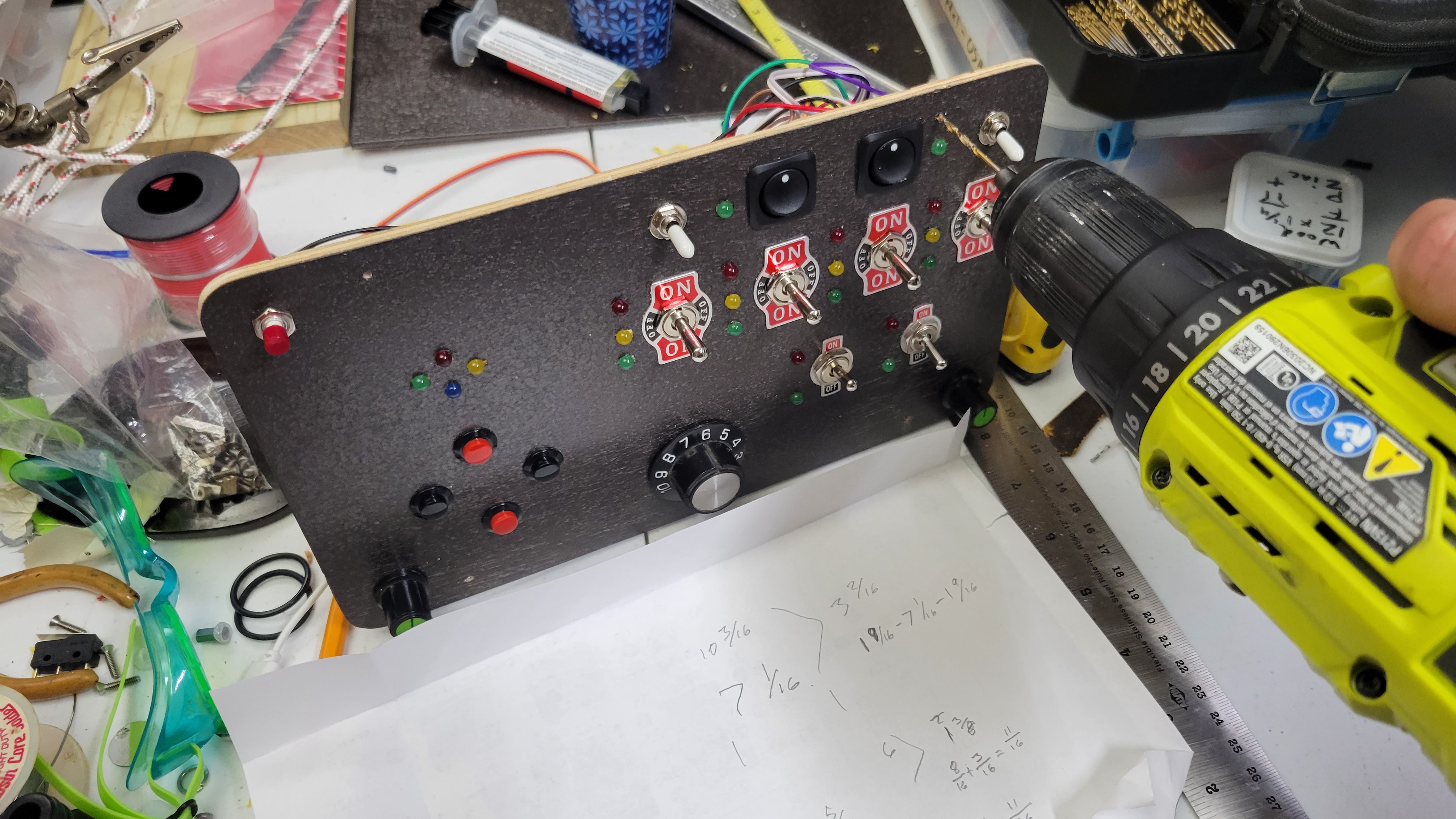
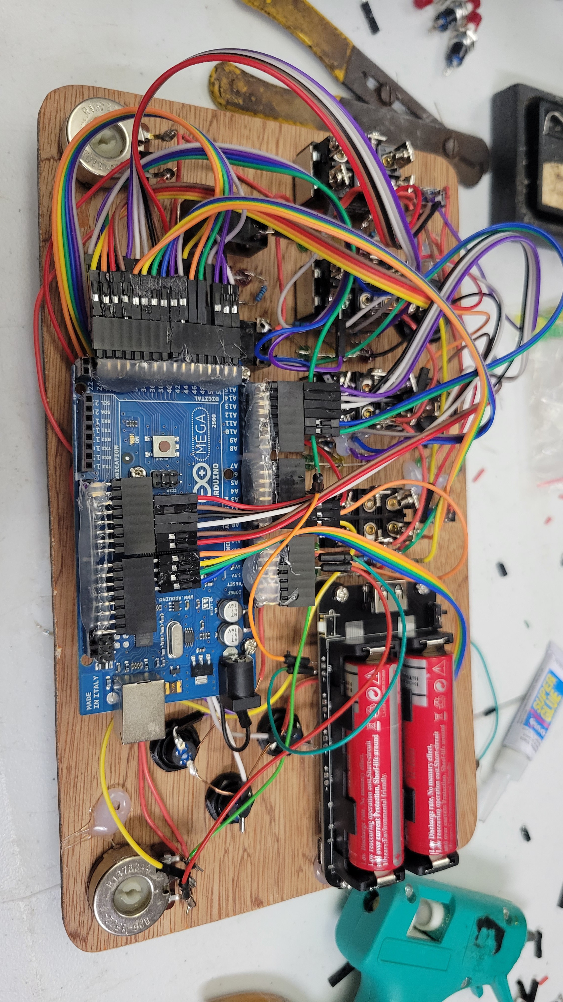
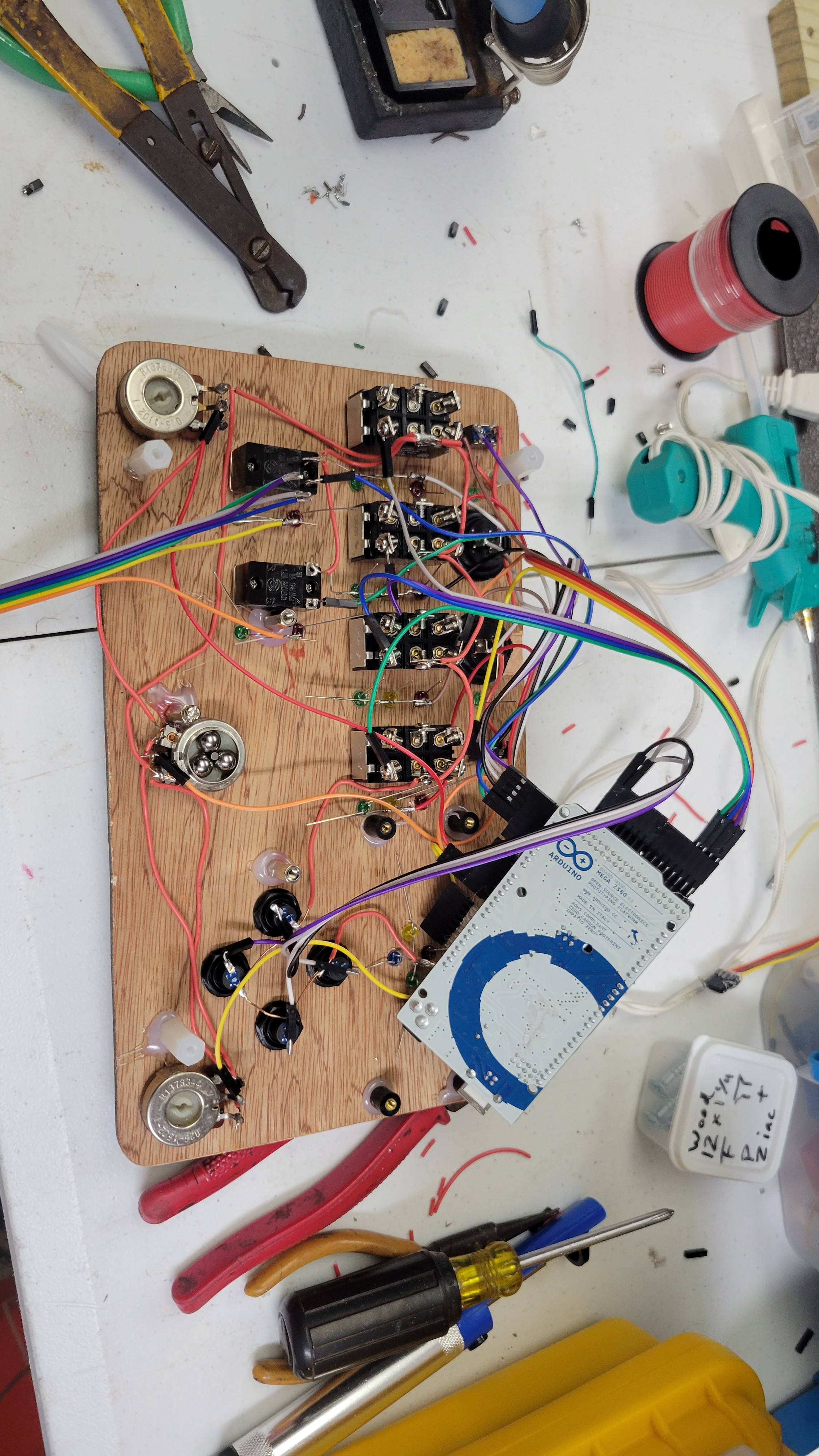
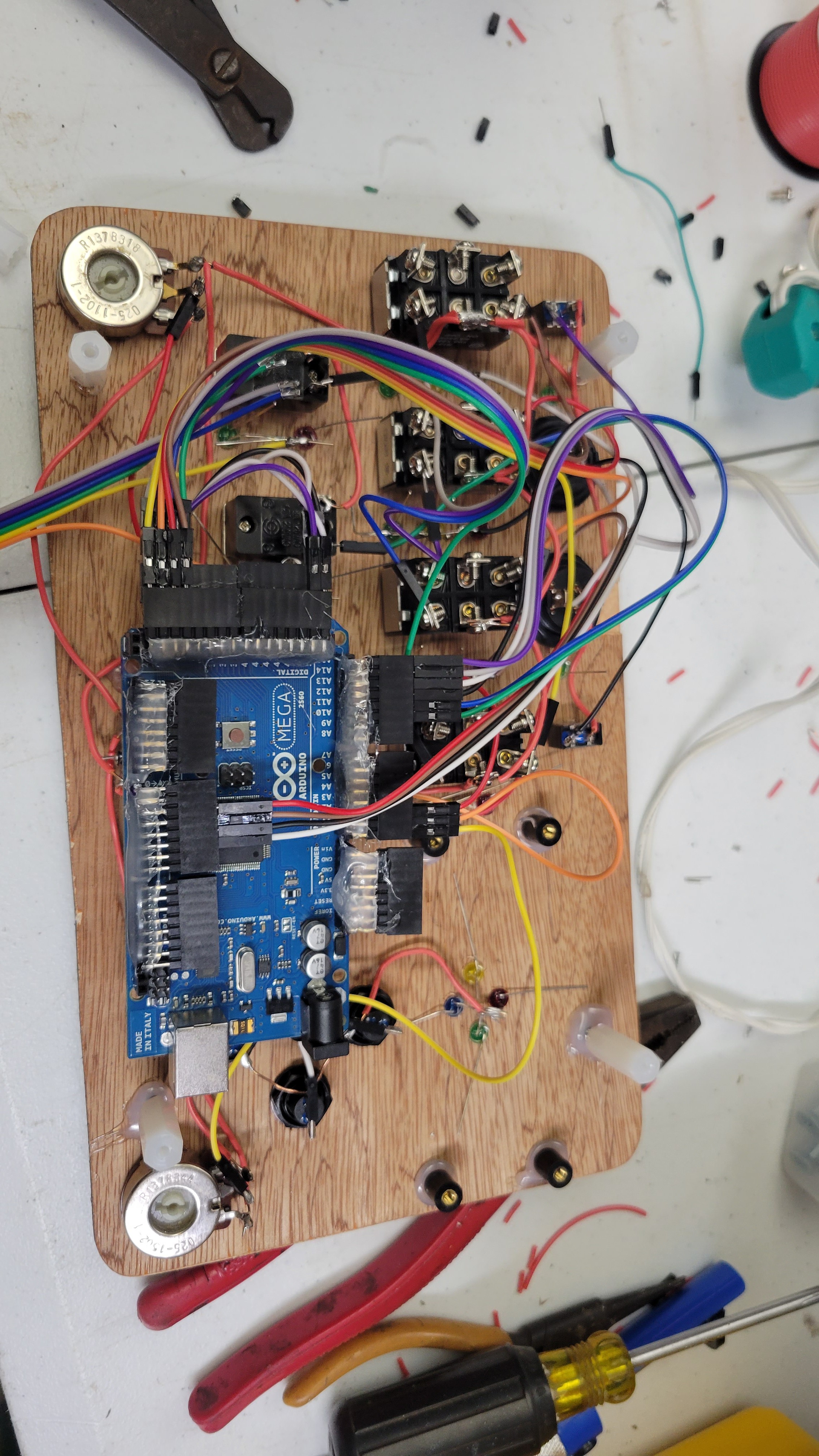
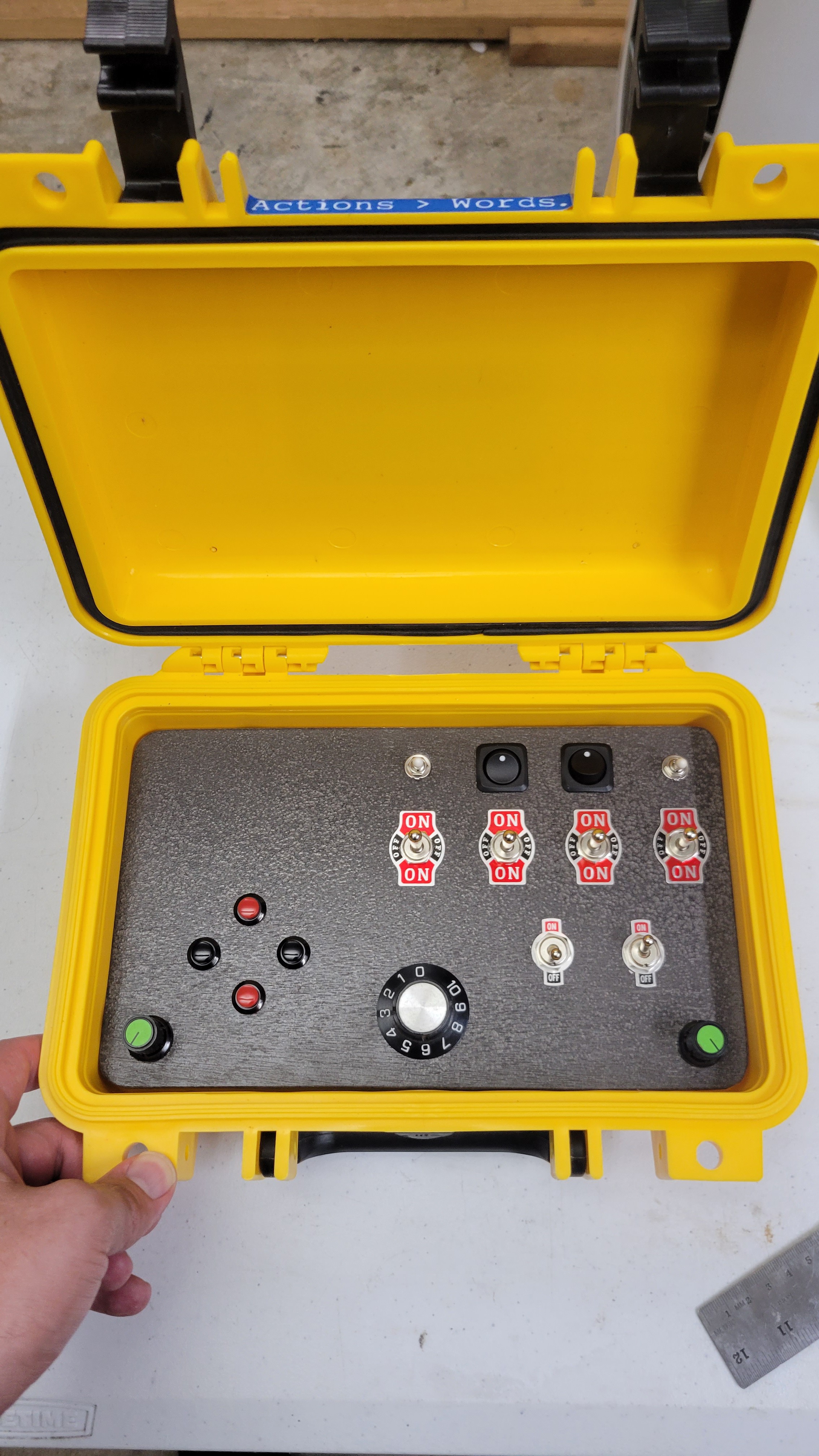
The Base:
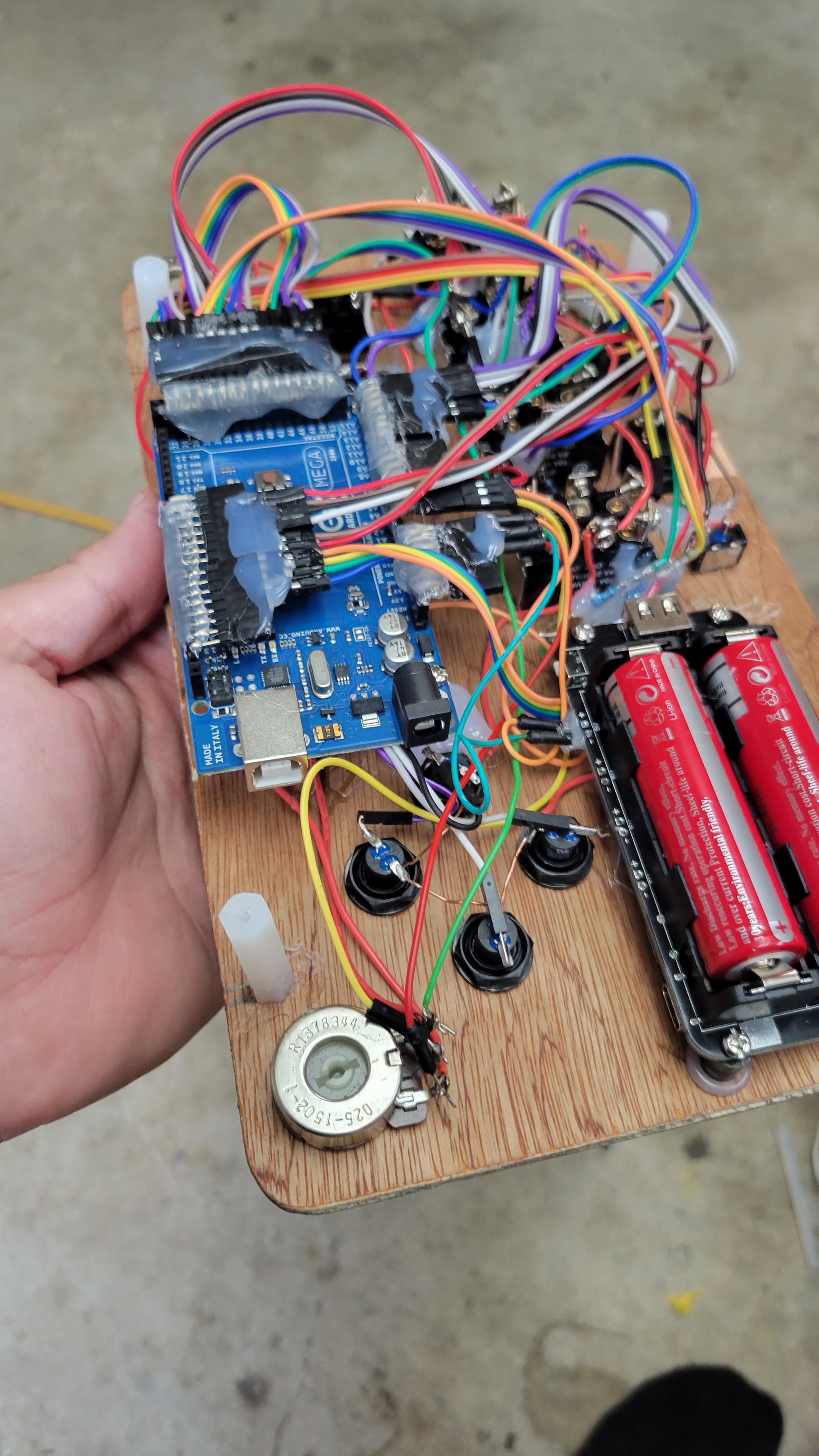
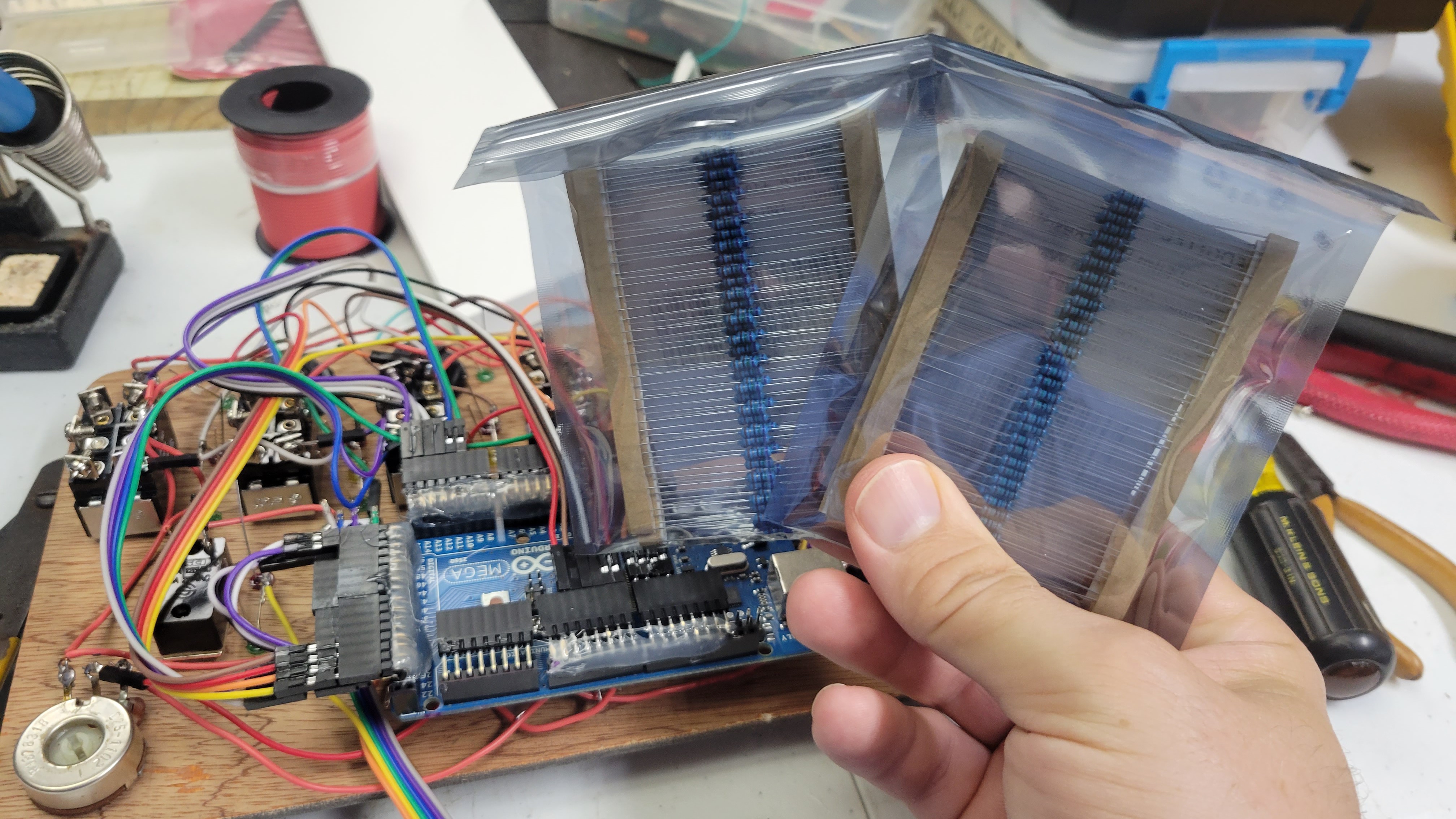
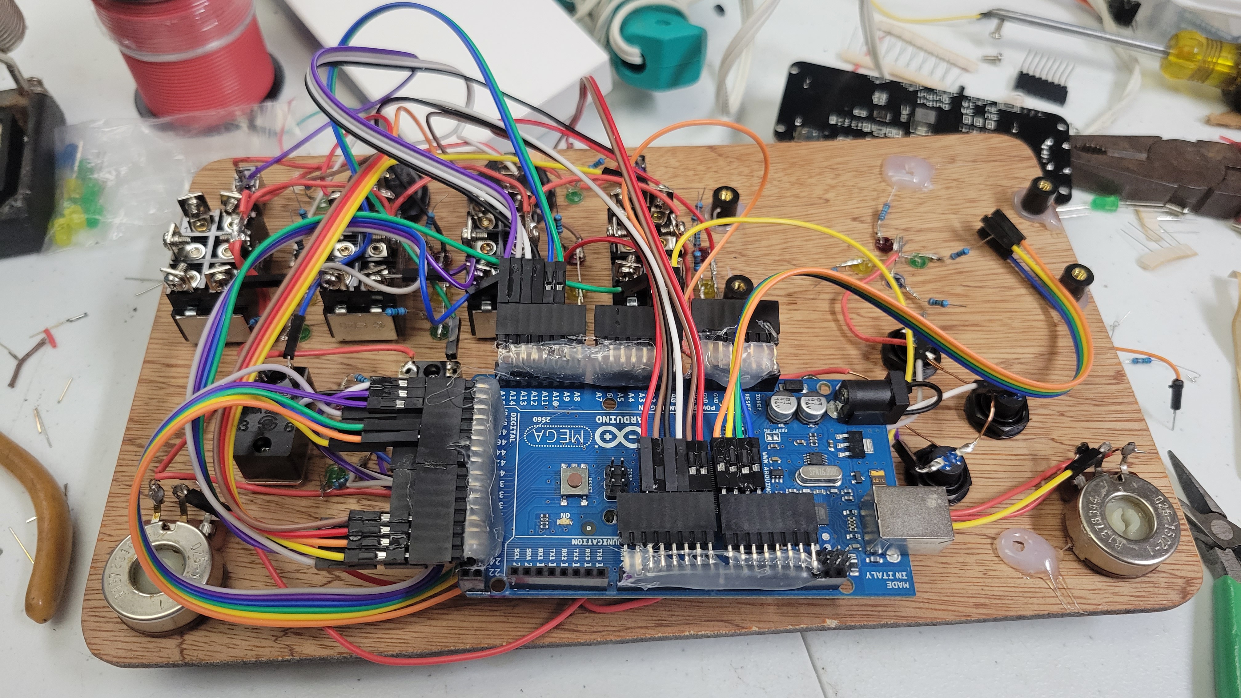
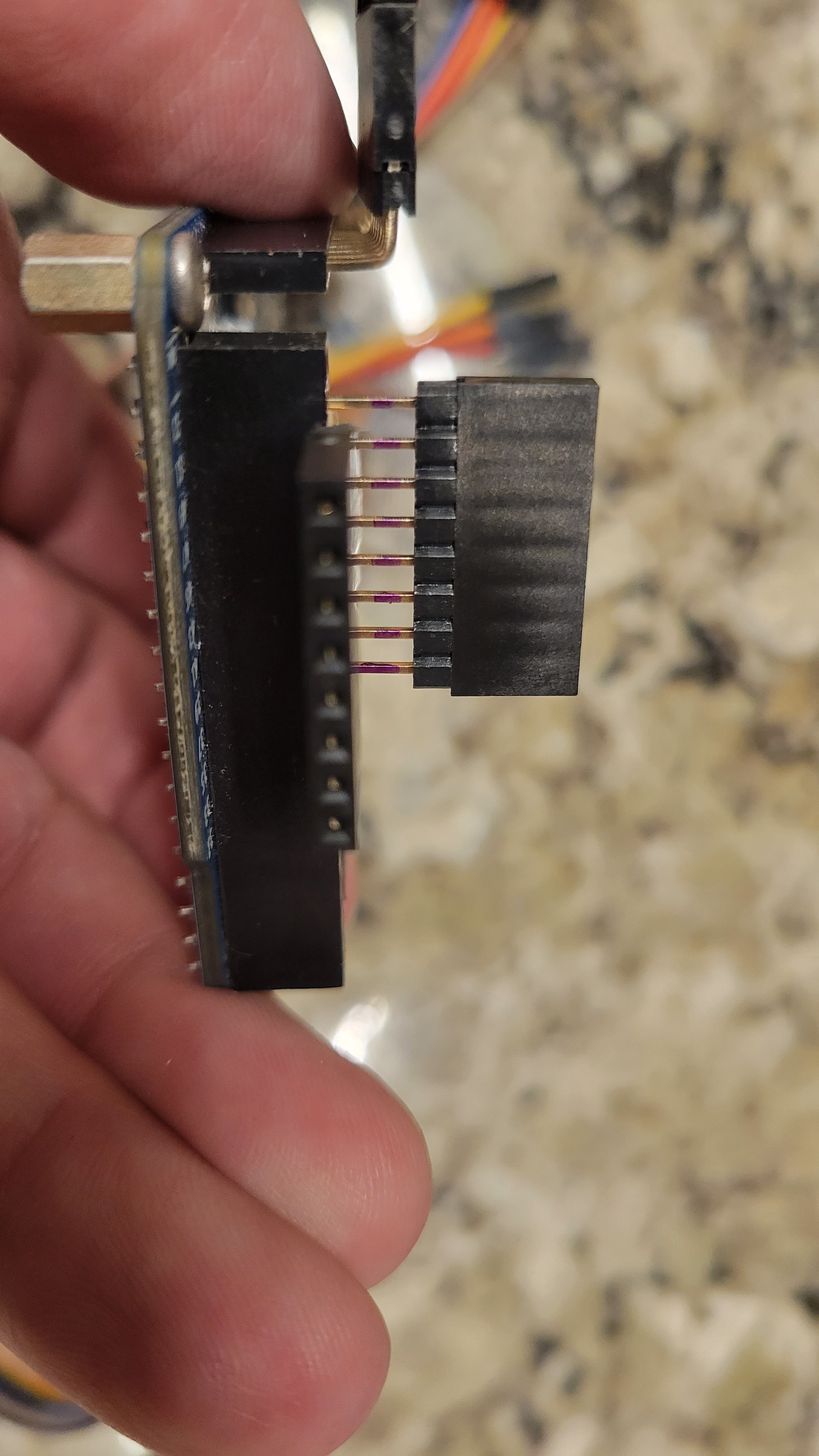
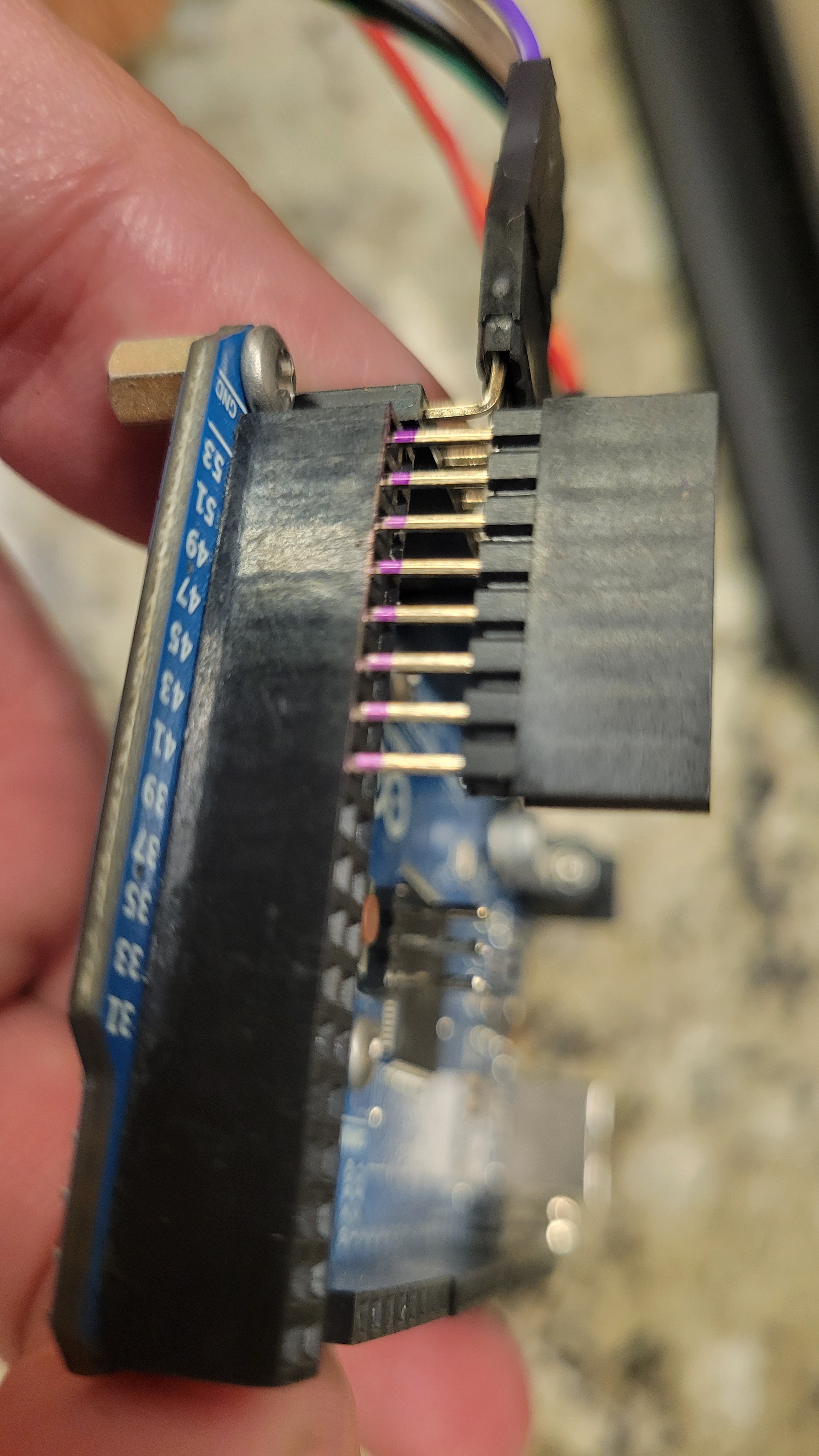
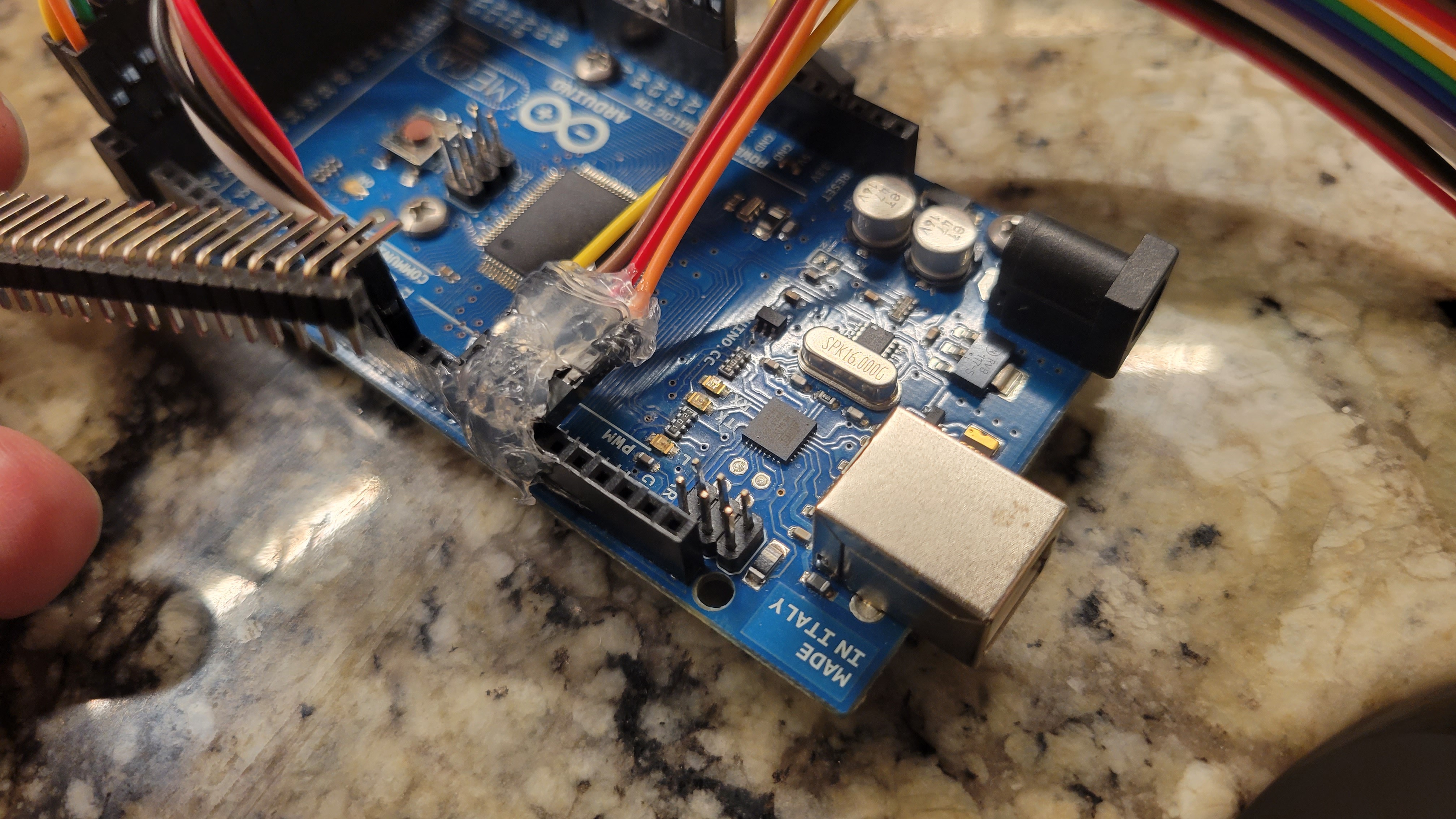
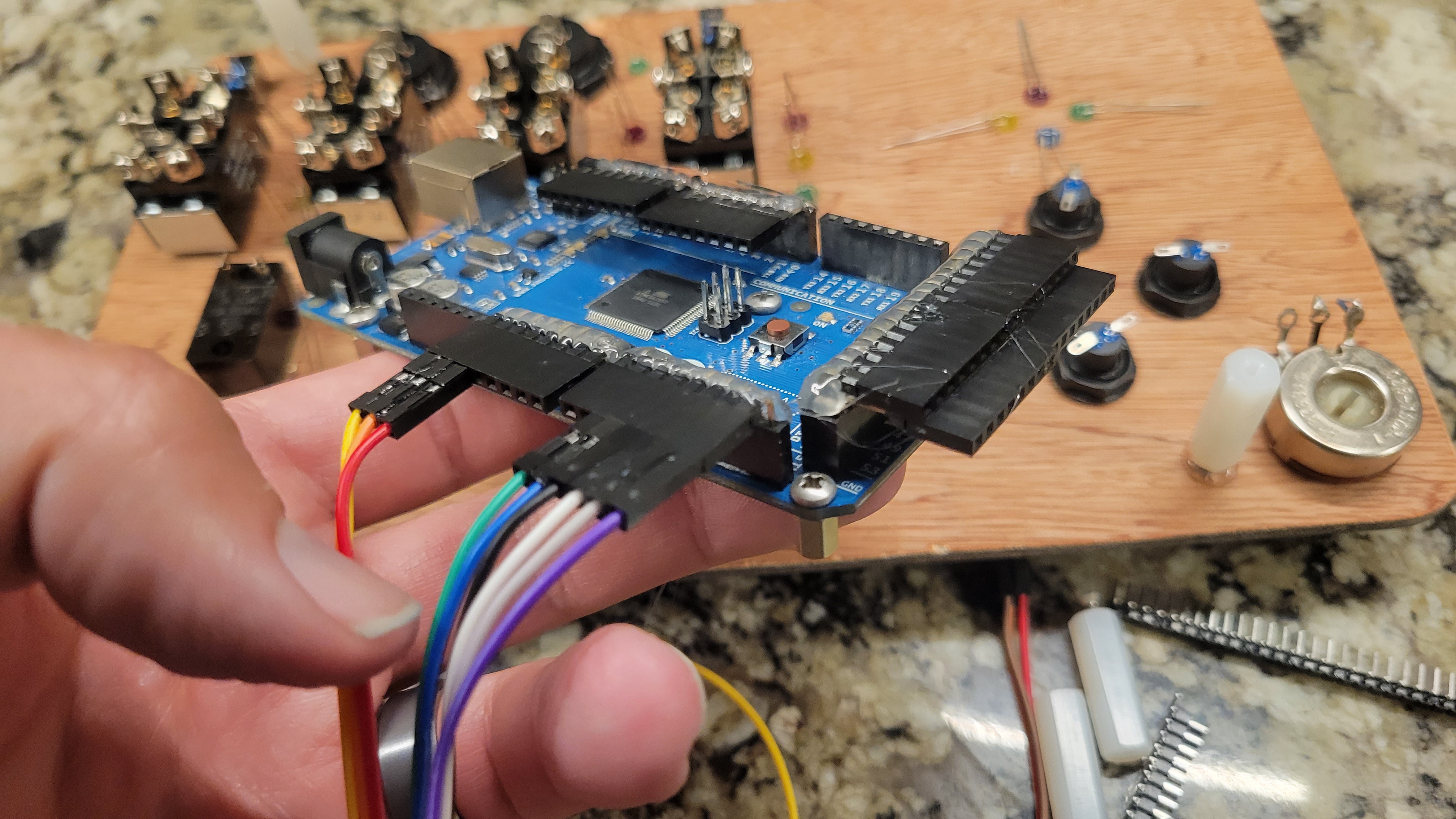
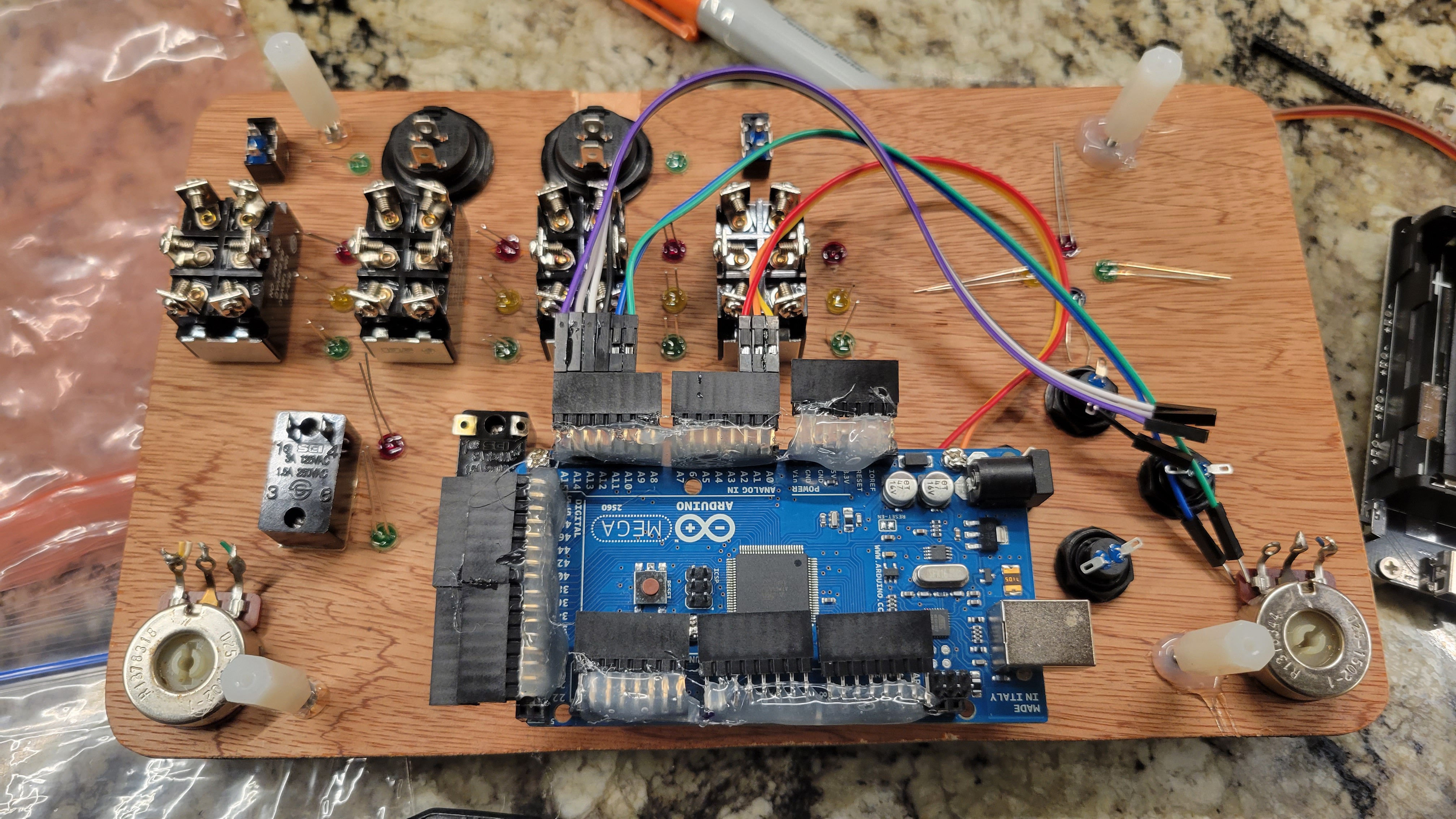
The main interactive portion is all contained in the base. It houses an Arduino Mega 2560, as well as a power supply that holds 2x 18650 cells in parallel, with built in charge circuit, and 3.3v and 5v boost regulated outputs. I am only using the 5v output. The power supply has a low current sleep-mode that is currently not being utilized, but even if this thing stays on, those cells will take a long time to discharge.
Interactive and Upgradeable
Hardware Design Basics

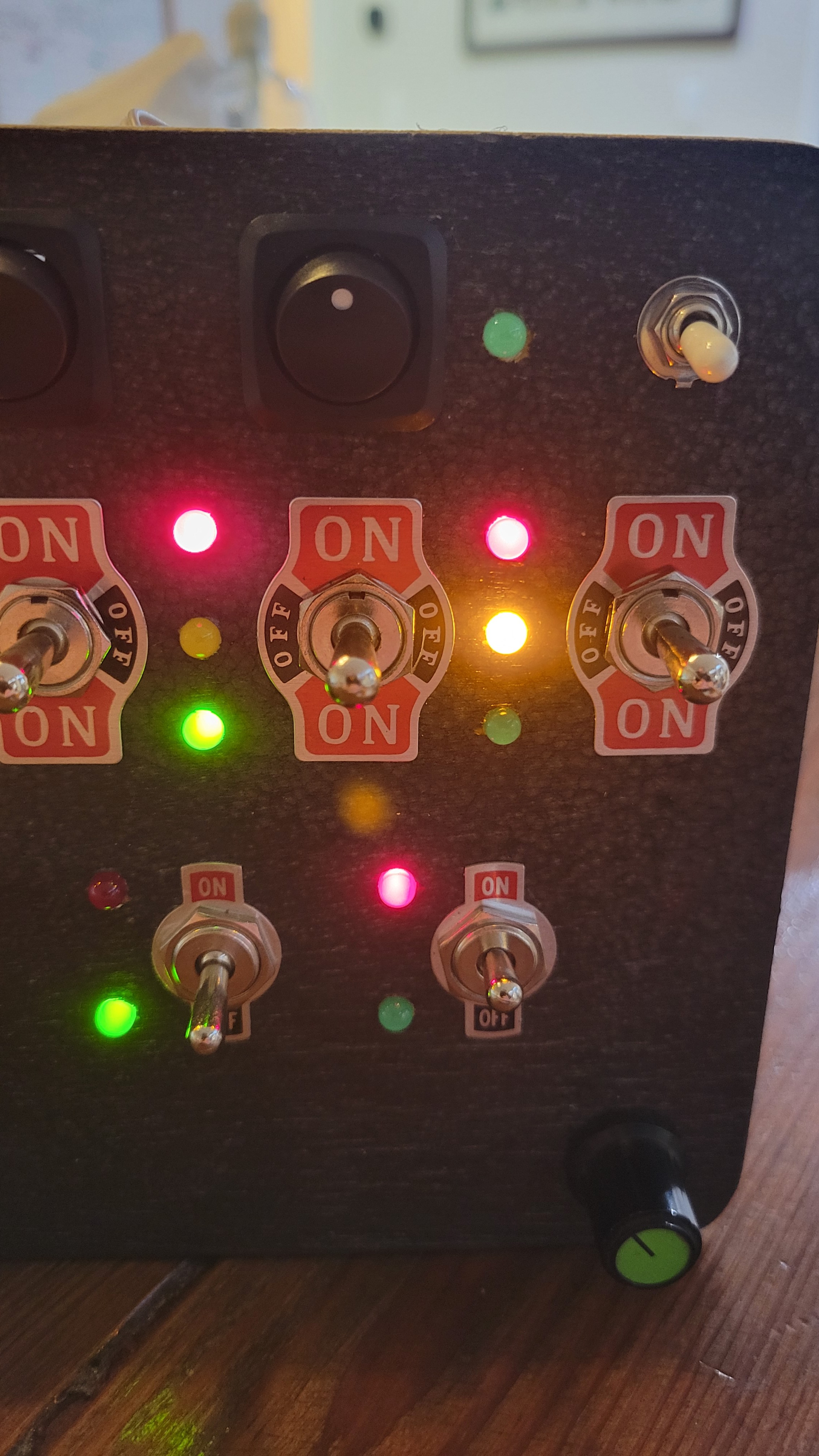
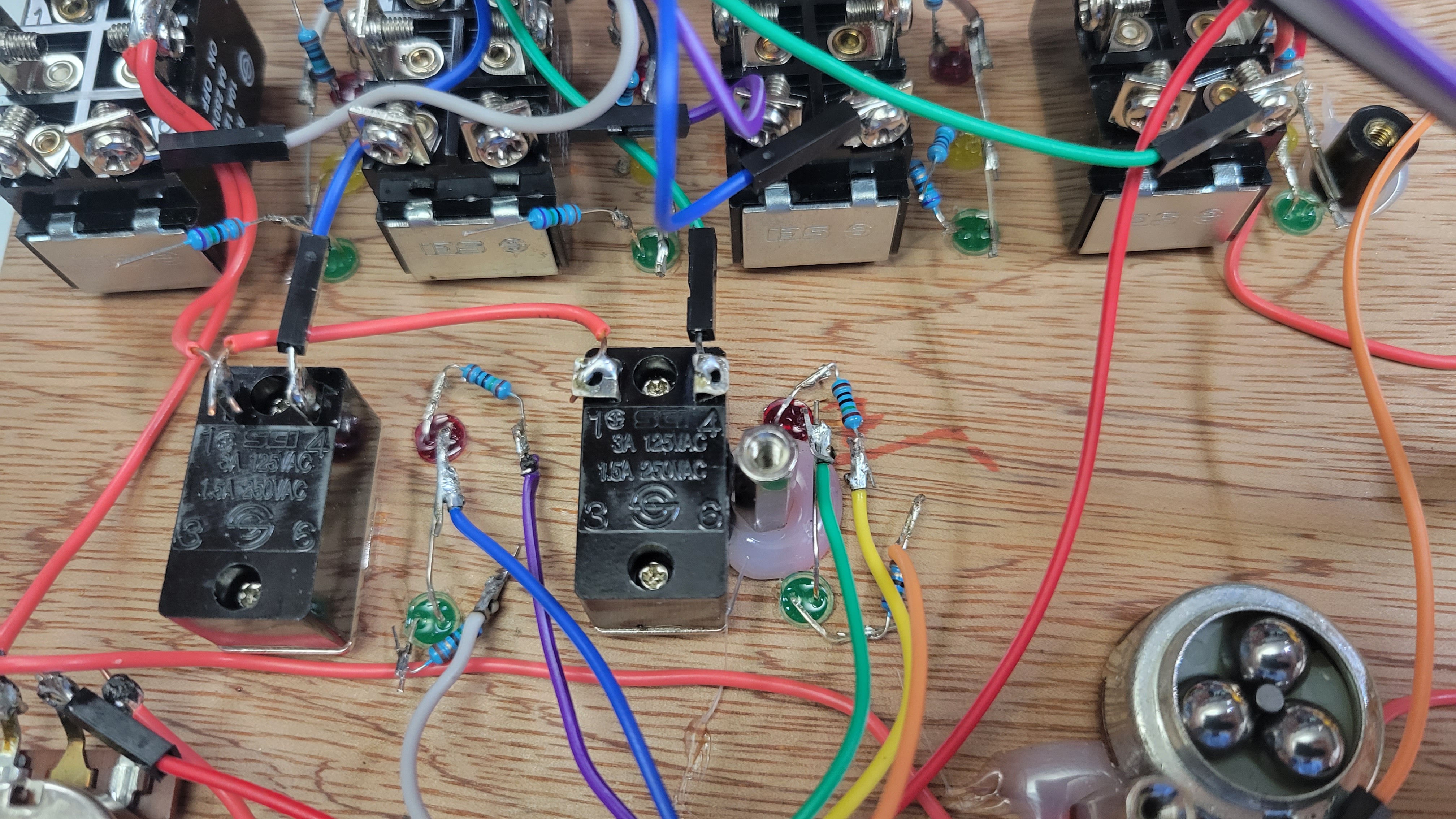
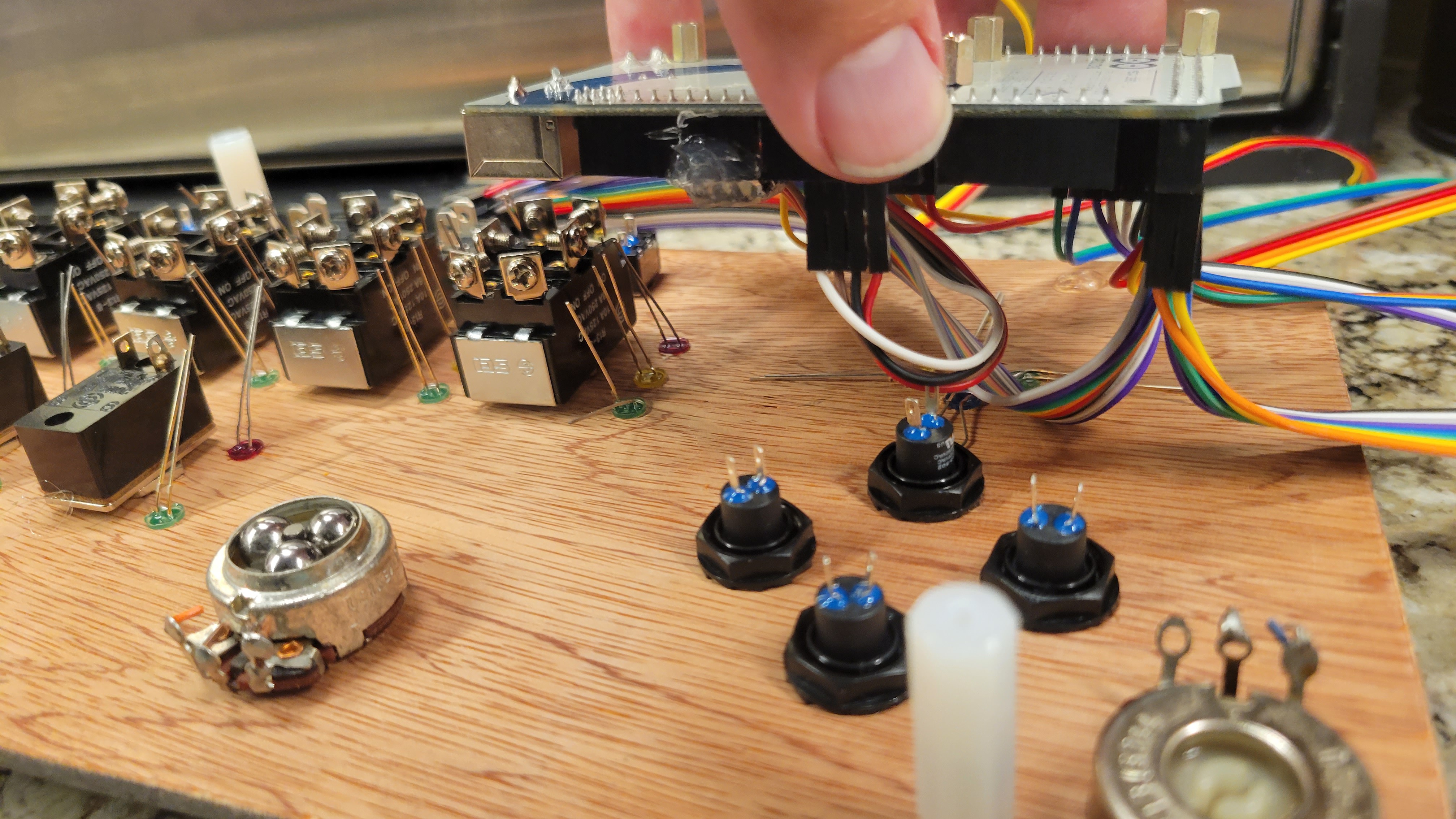
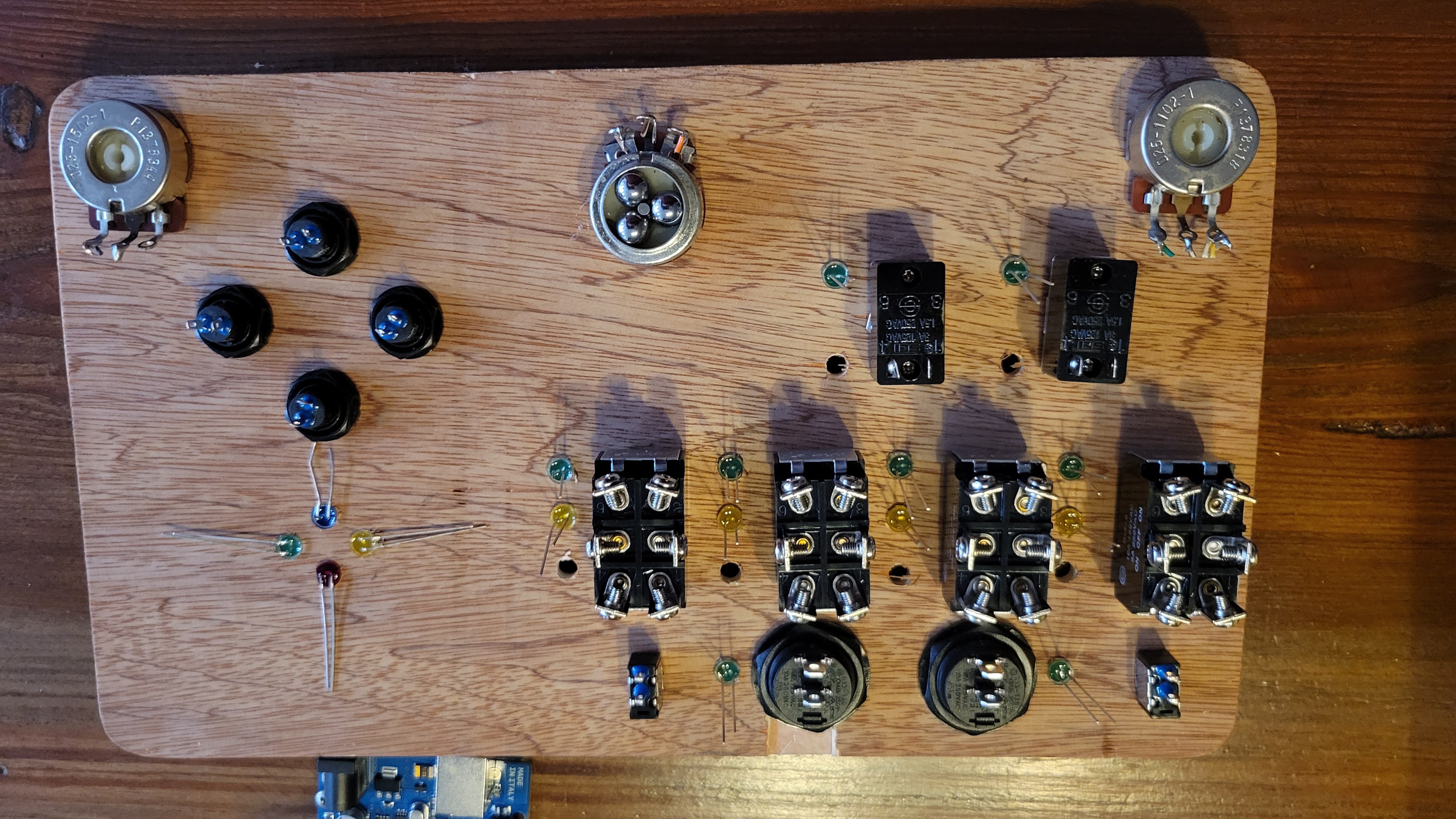
I designed the base portion to be highly flexible. Each switch has a dedicated input on the Mega, and I grouped the LEDs by switch. For the LEDs next to the switches, the Anodes are powered by an analog output for PWM control of the group, and the cathodes terminate to a Digital output through a current-limit resistor. This allows me to control dimming for each group of LEDs next to a switch as well as which LED is on, and I can turn on all or none. For the LEDs that are by themselves, they each use their own analog output (because I had plenty with the MEGA!) so I can dim them.
Programming Basics
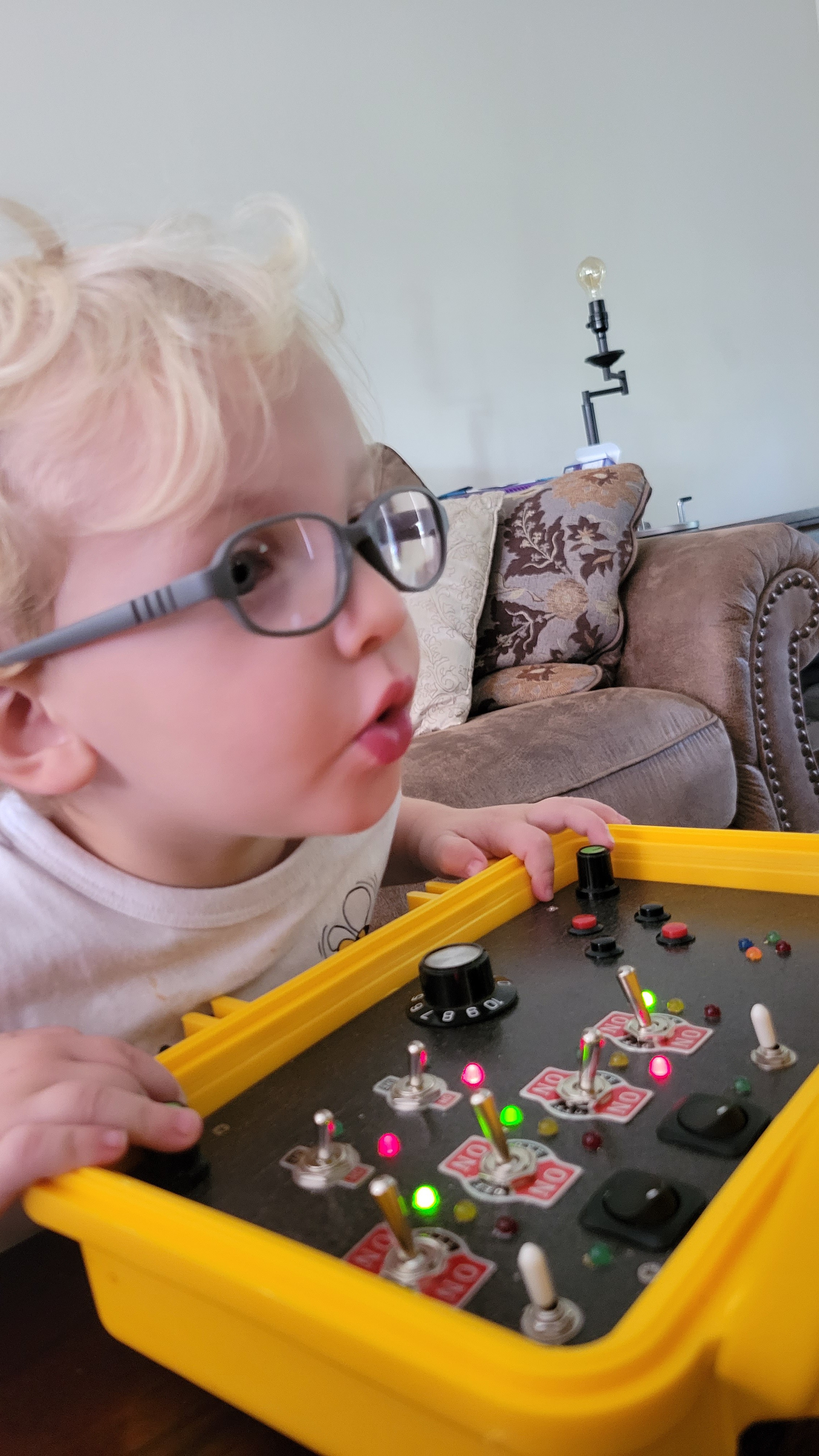
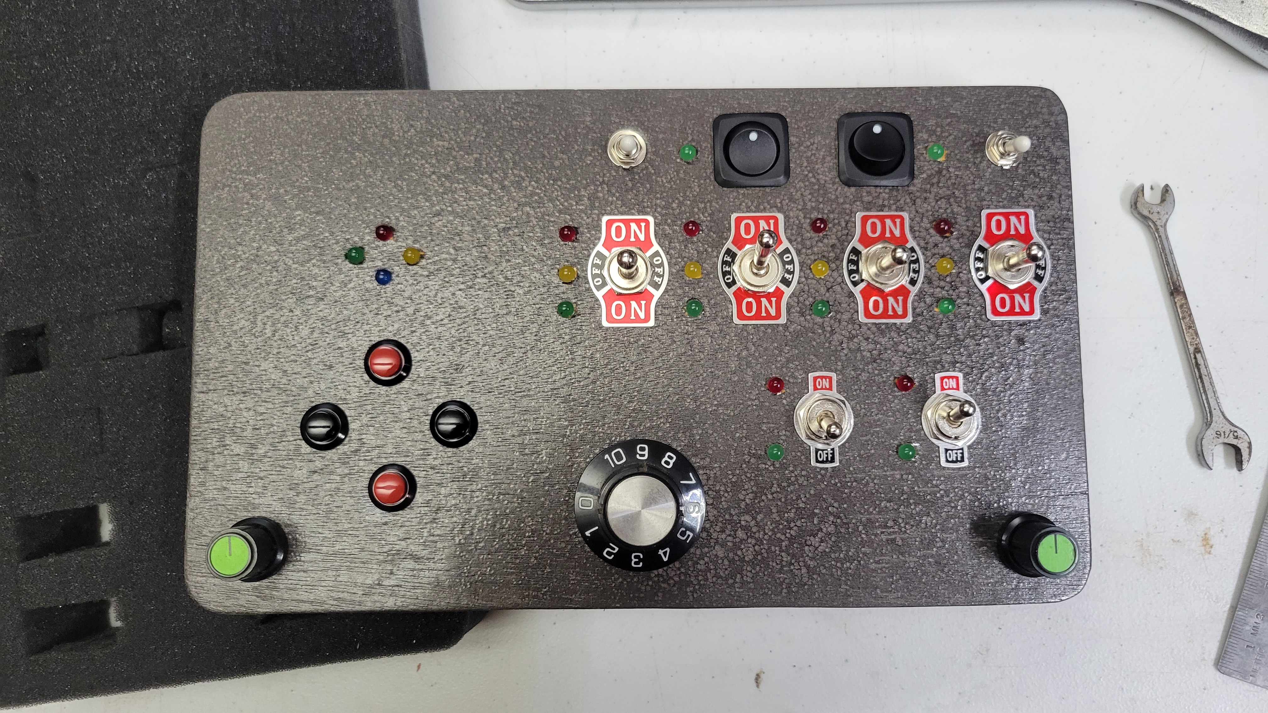
For the moment, Each LED simply displays the status of the switch next to it. This is to start by teaching simple cause-effect behavior. The "simon-says" buttons and LEDs simply light up for 1 second when the associated button is pressed. The potentiometers dim arbitrary sections of LEDs, and I have a floor at 10% so they don't turn off with the pots. Despite my desire to add more features, I made sure it just worked with the basic program.
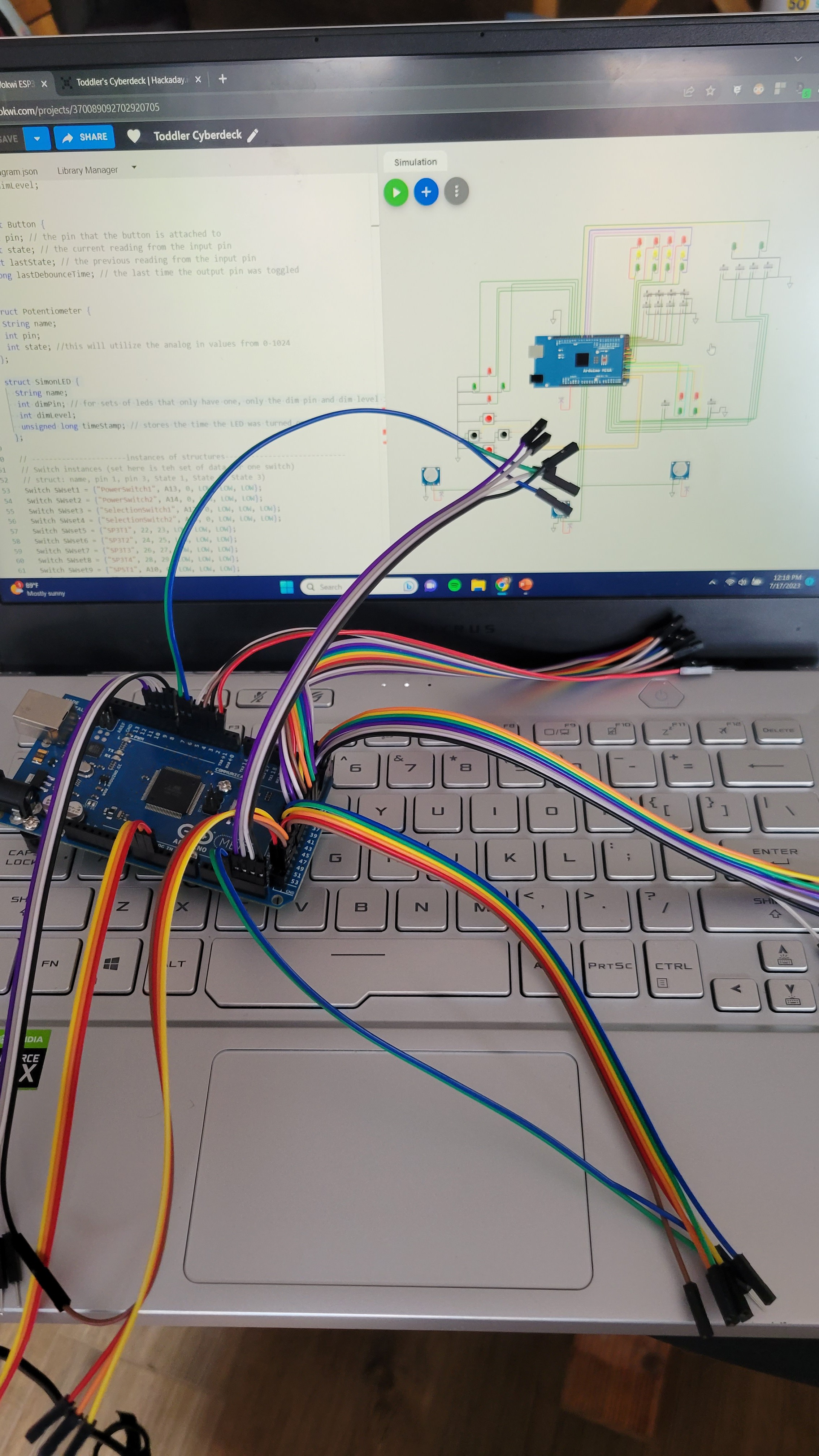
I utilized ChatGPT to write the majority of the code, as well as help troubleshoot when I had issues. You can find my conversation with ChatGPT HERE.
I created the schematic and simulated the code on wokwi.com prior to loading it on the arduino in the real world. You can access the simulation HERE. You can also copy it and modify it for your specific needs and switch configurations. I think this is much more useful than me posting my final code, as I have several pin assignment changes due to accidental wiring issues (fix it in software they say...).

Future Upgrades
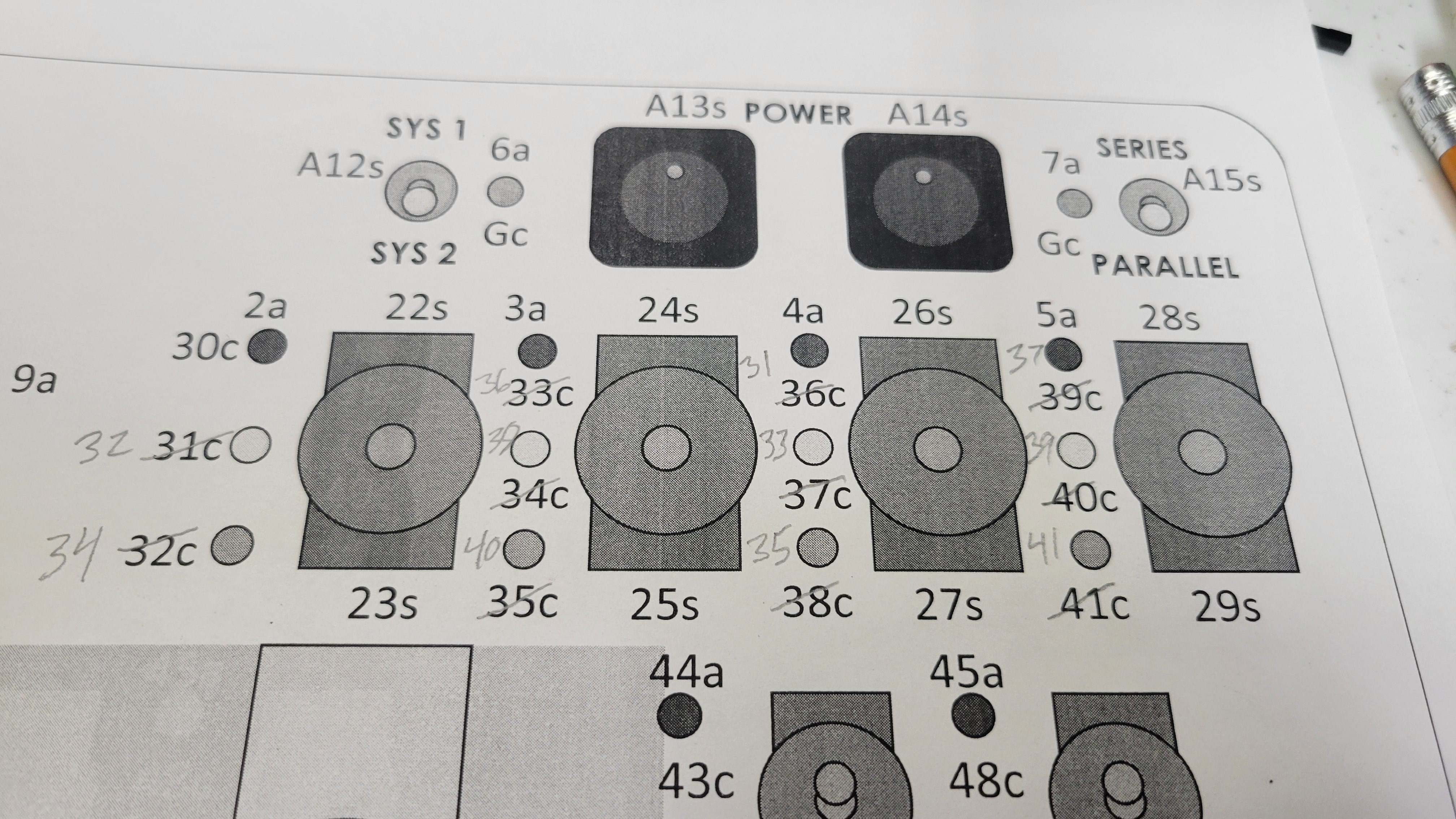
When I designed the switch layout, I had it in mind to create some simple logic puzzles for the next version. Here are my list of updates for V2 of the software, when I make it:
- White toggle switches will activate different modes. Top right will activate puzzle mode (up) or blinky mode (down) on the switches; top left will activate the simon-says game.
- Switch puzzle game: The LEDs by the switches will all turn off except for the top left switch. An LED next to that switch will flash until the switch is set to match. Each time a switch is set to the same position as the flashing LED, the next switch will activate, leading through all 6 switches.
- Blinky mode: Instead of the POTs controlling random dimming, I'm going to change the LEDs to blink/pulse. The middle pot will control the direction (pulse left to right or right to left, with center all at the same time), the left pot will control the frequency of the on/off cycle, and the right pot will control...

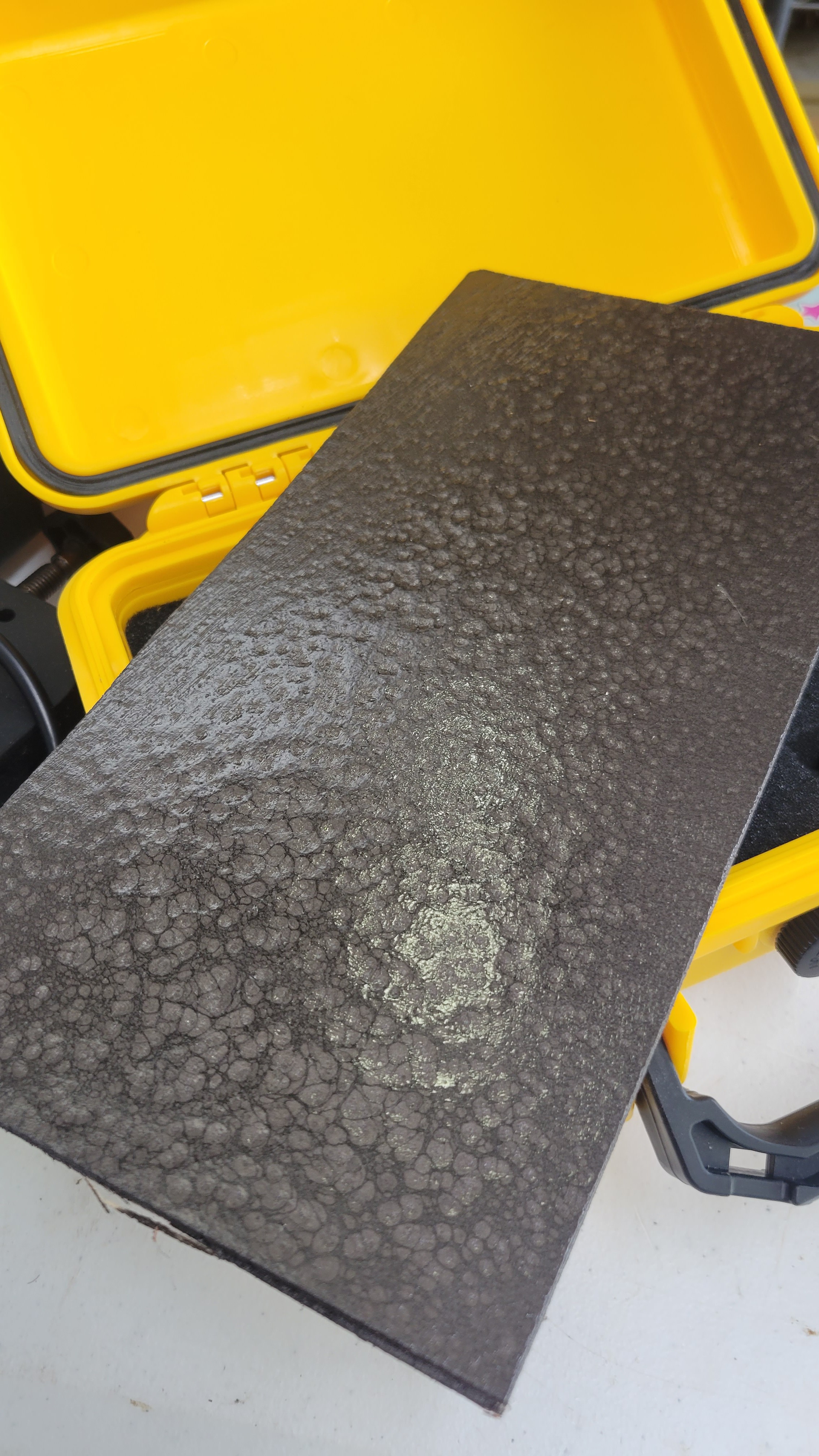
 Time to pick the paint (with Daughter 2)! She chose the hammer tone paint:
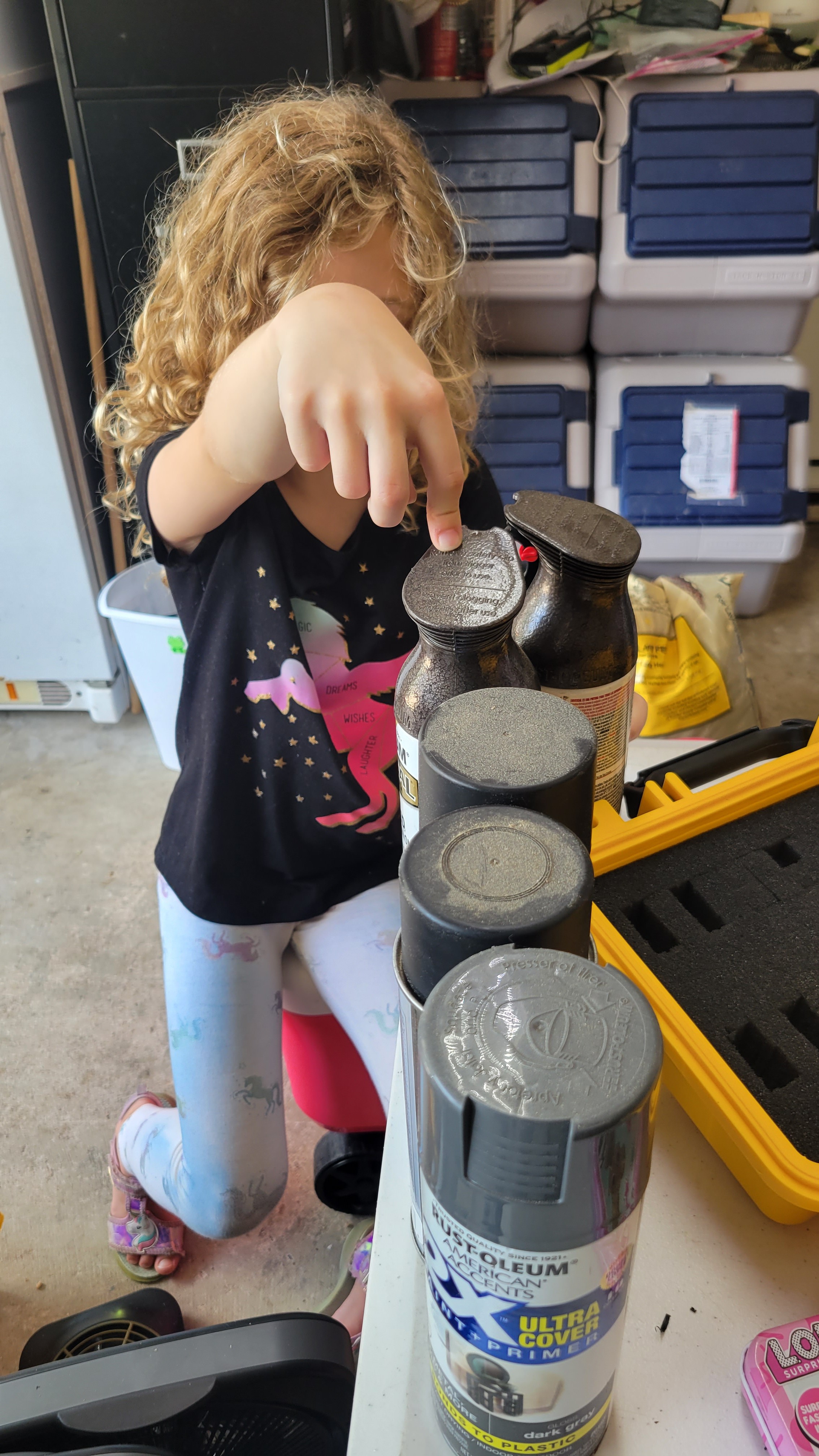
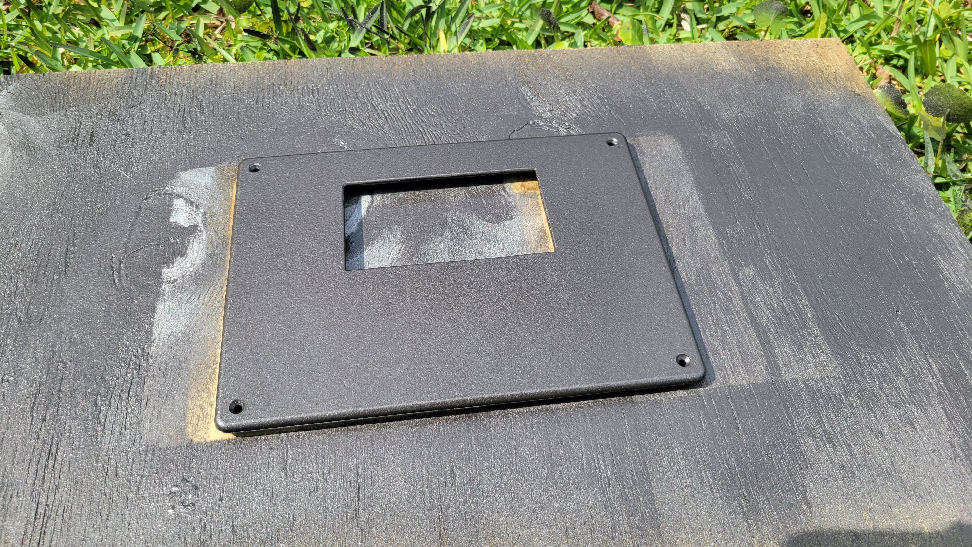
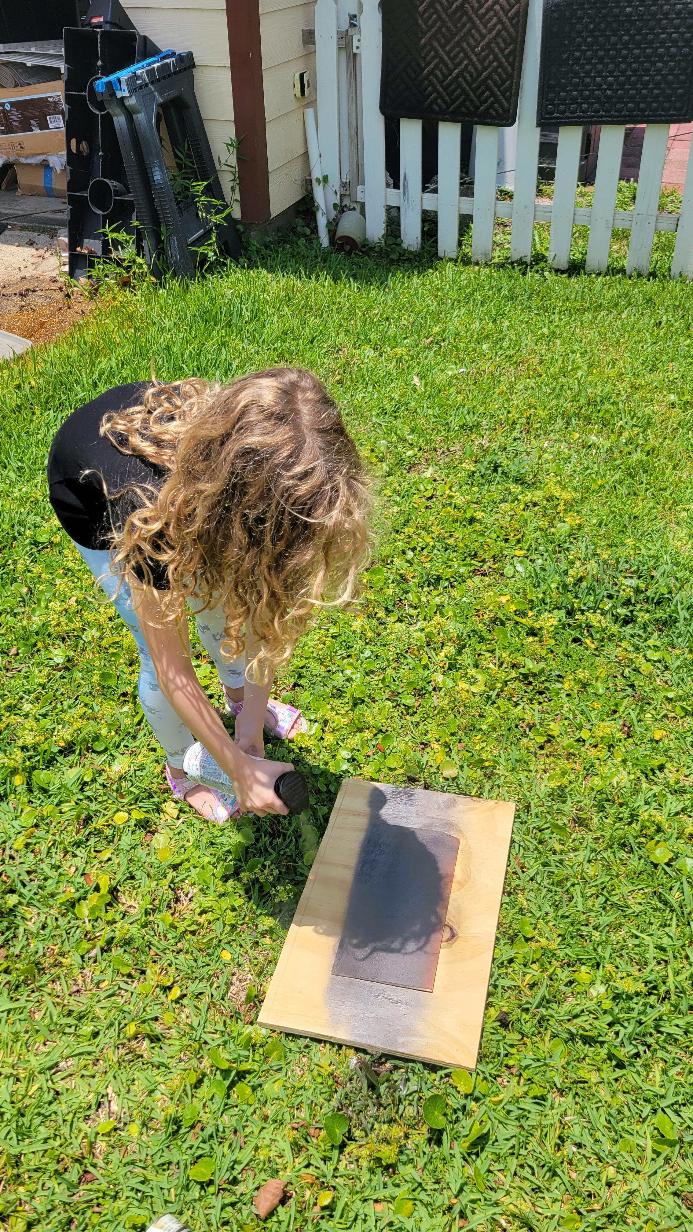 Spraying the display bezel:
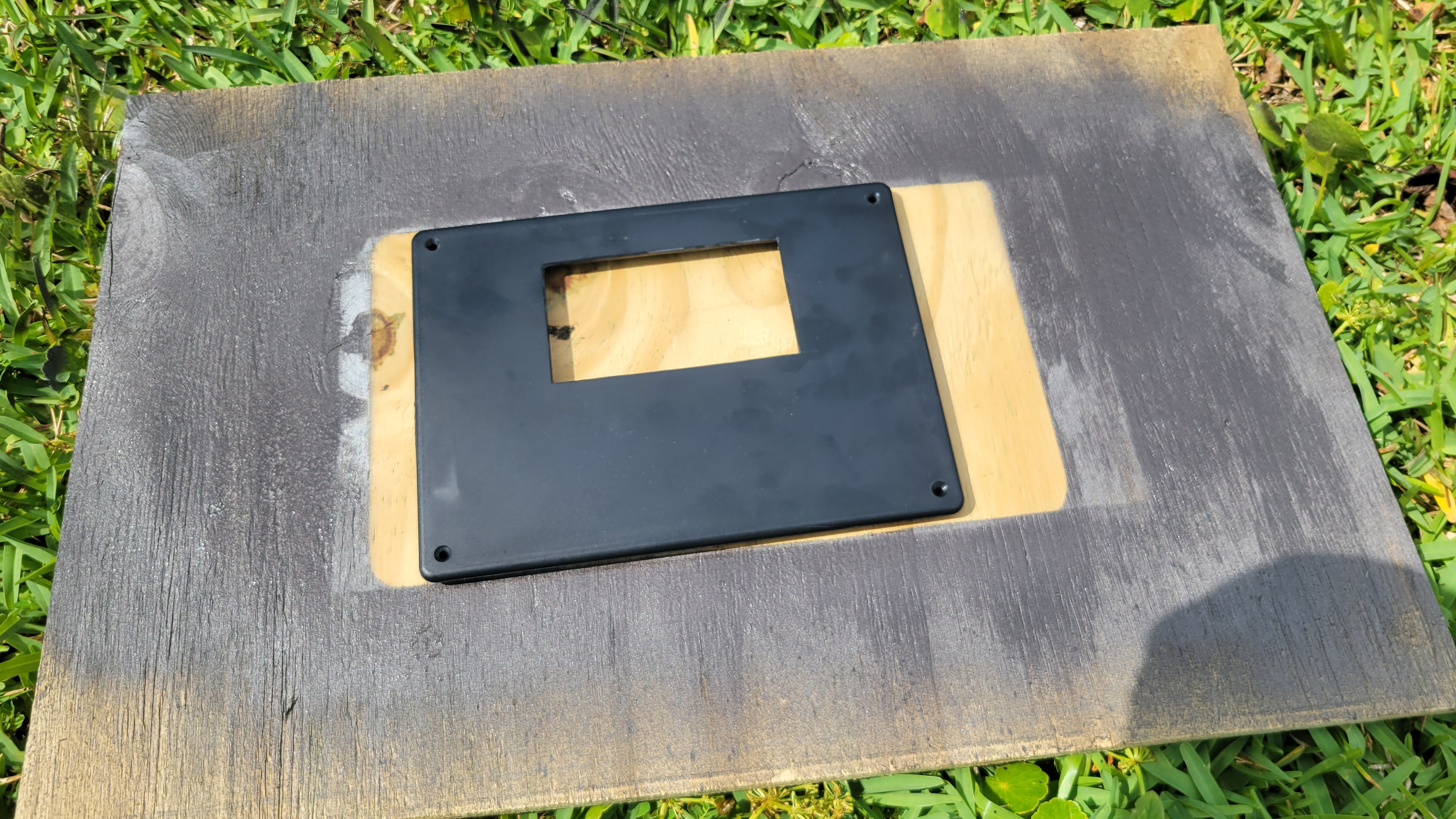
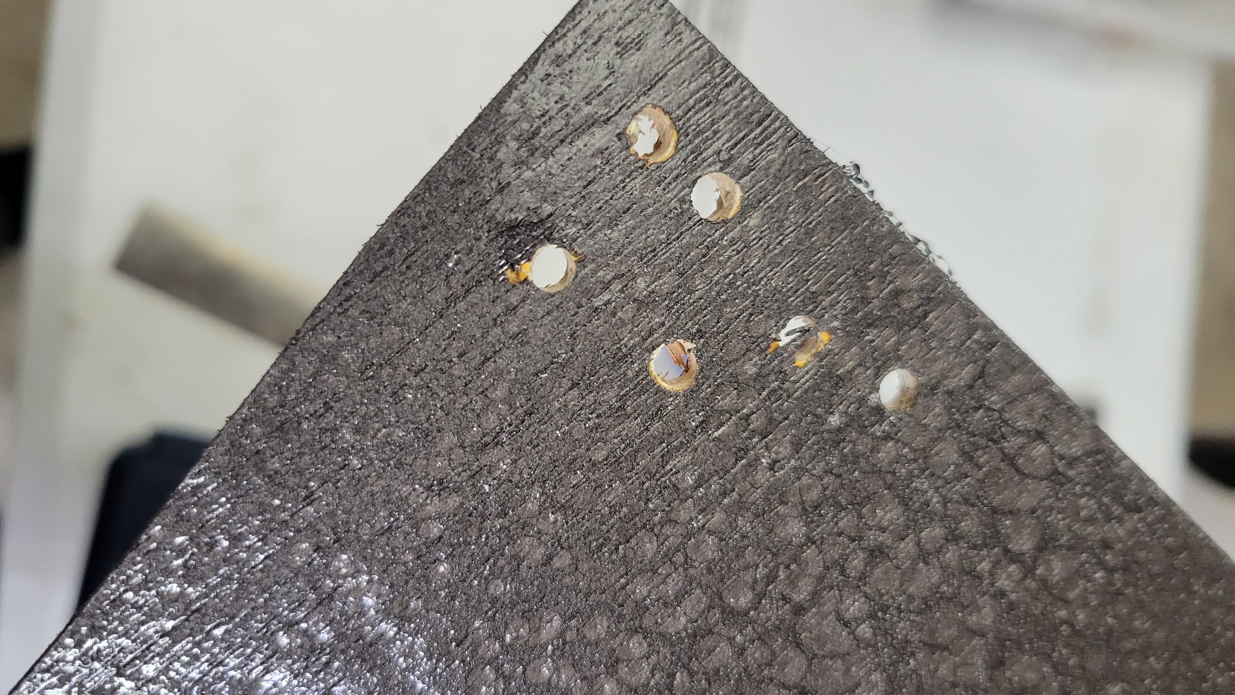
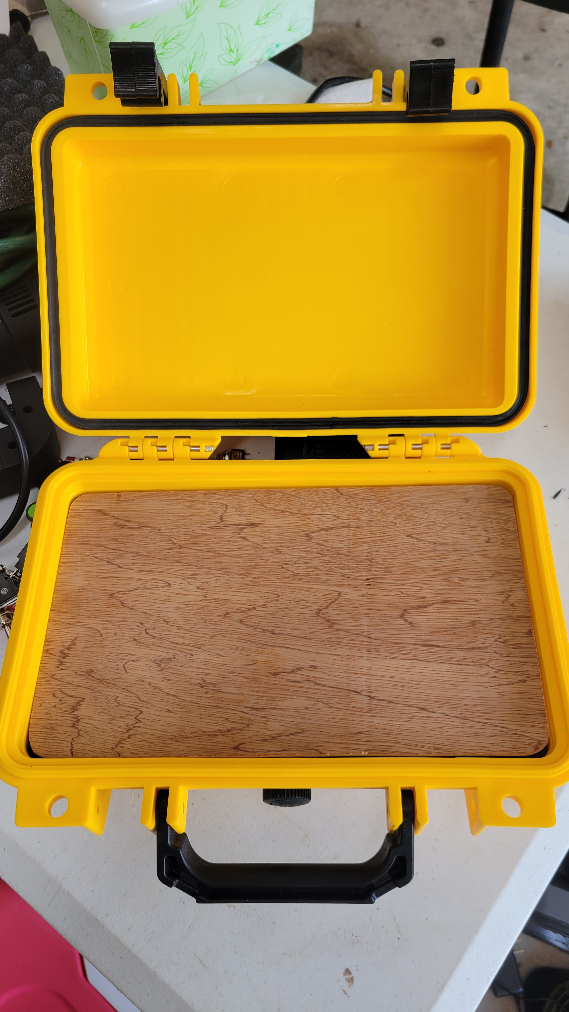
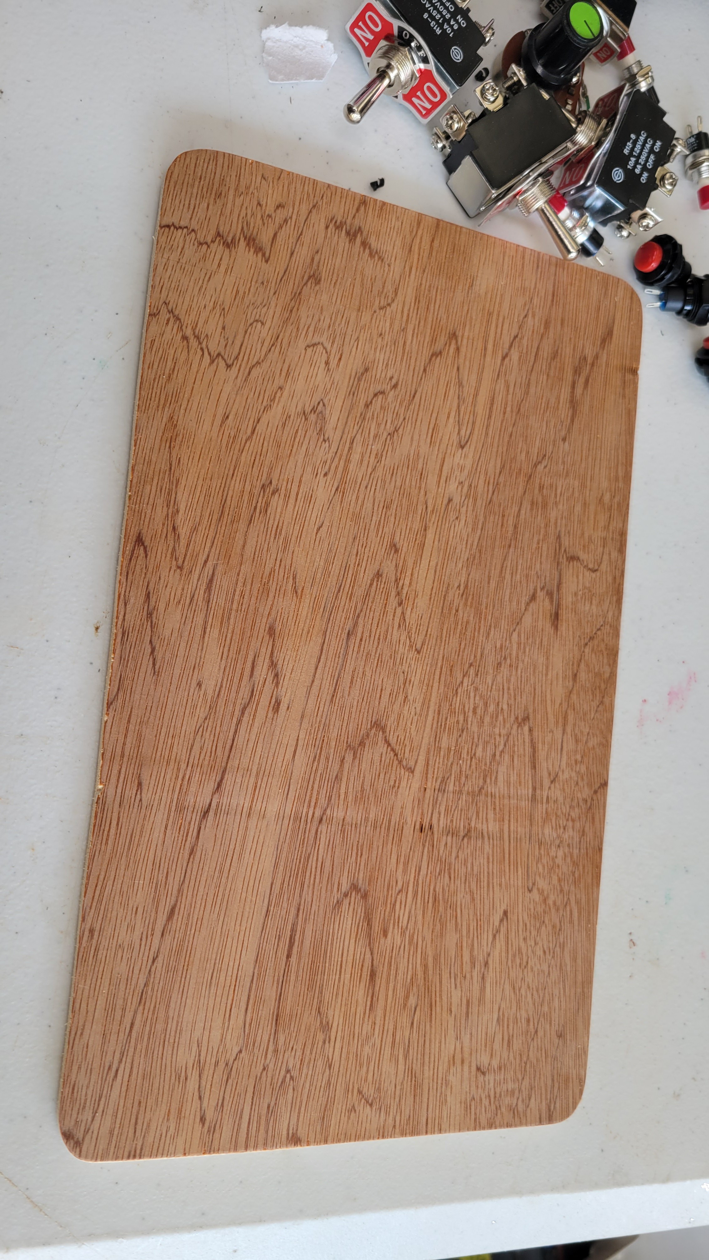
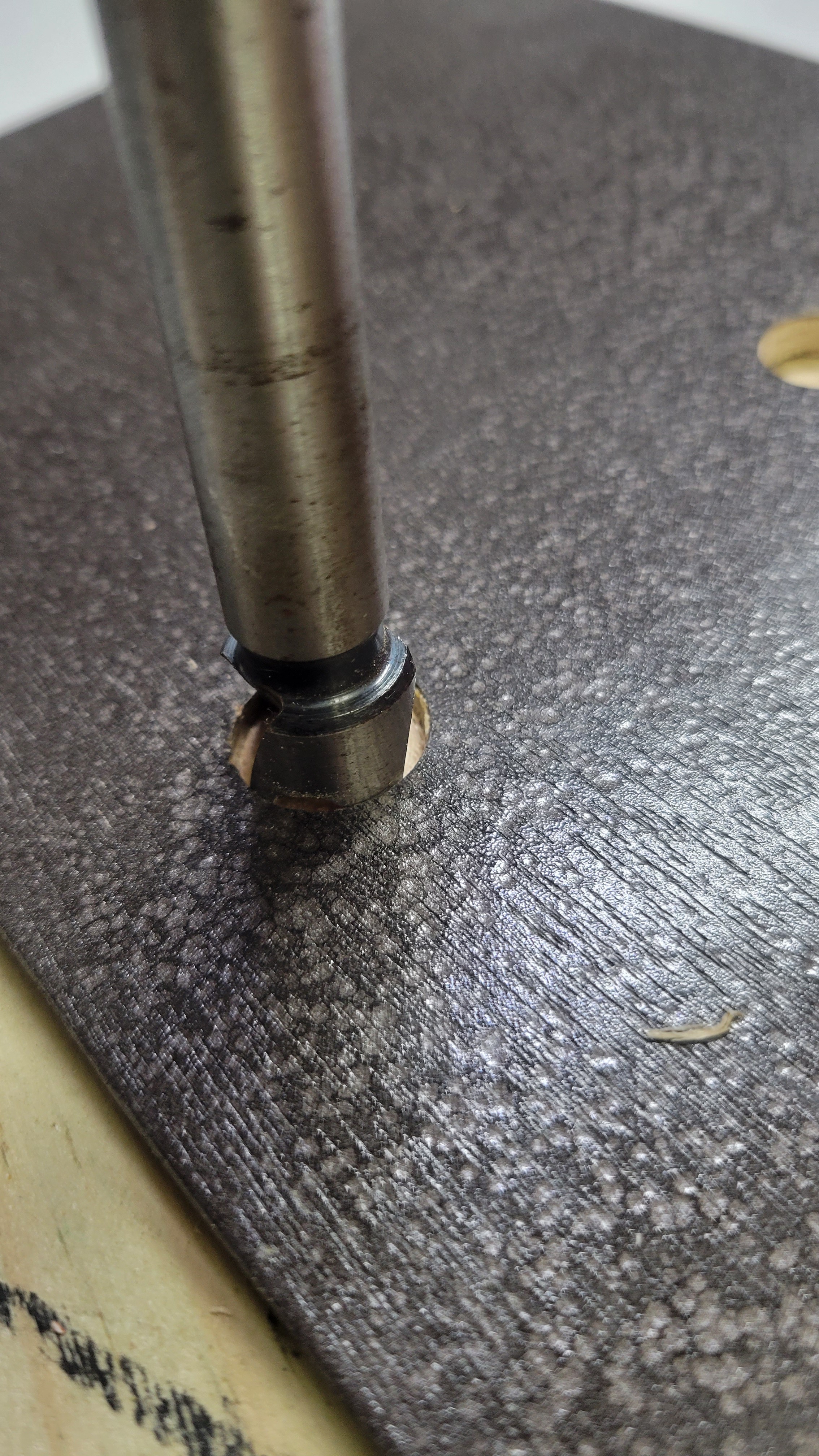
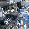
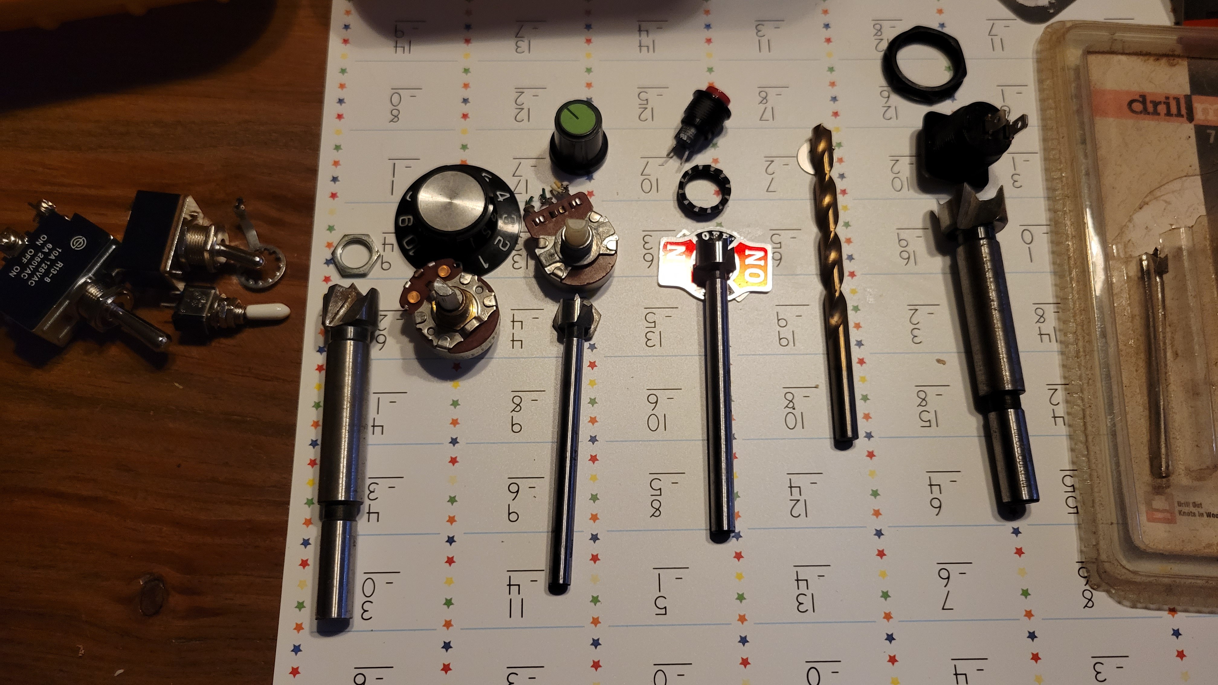 Board is marked out and one hole drilled for test fit.
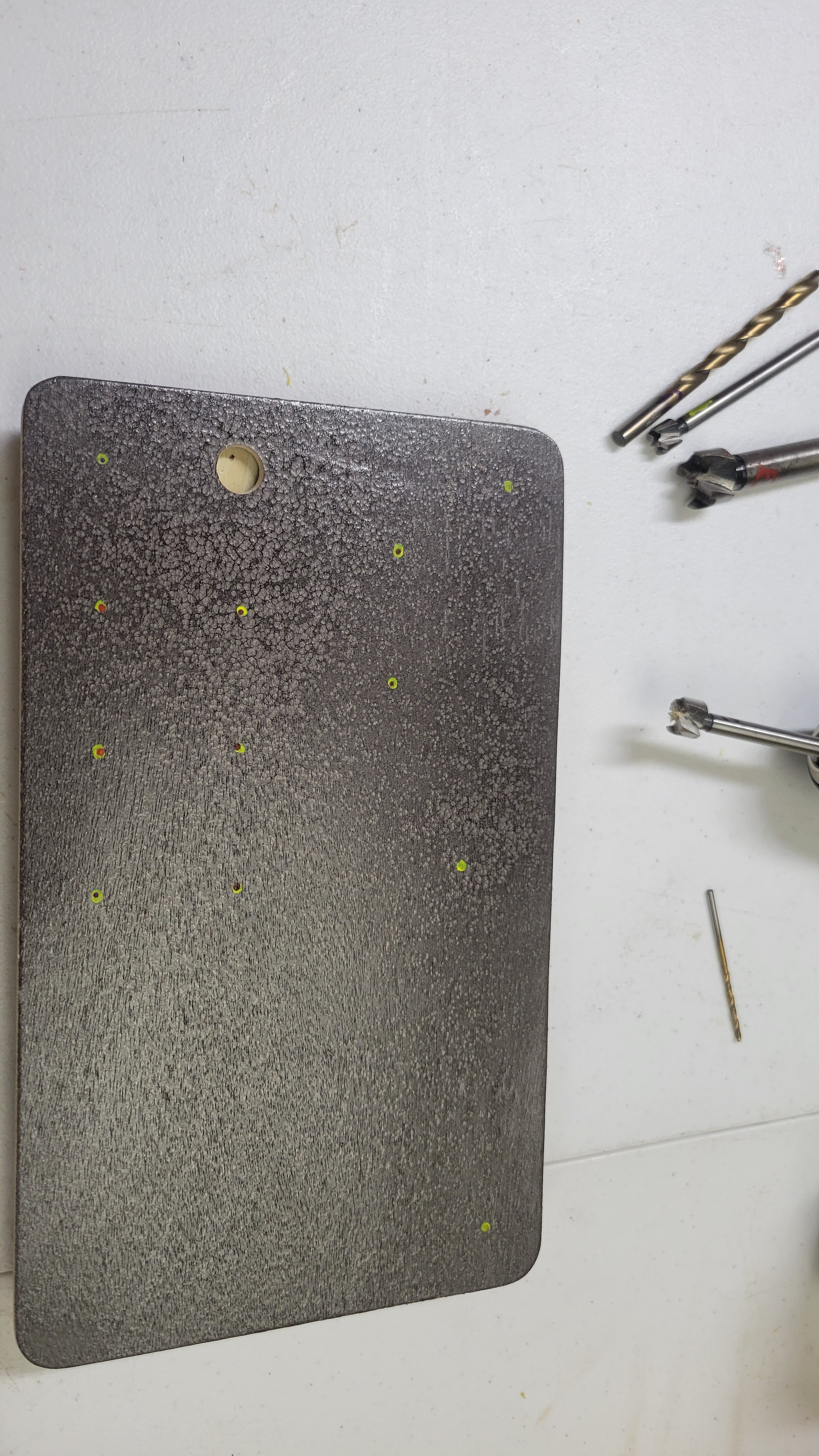
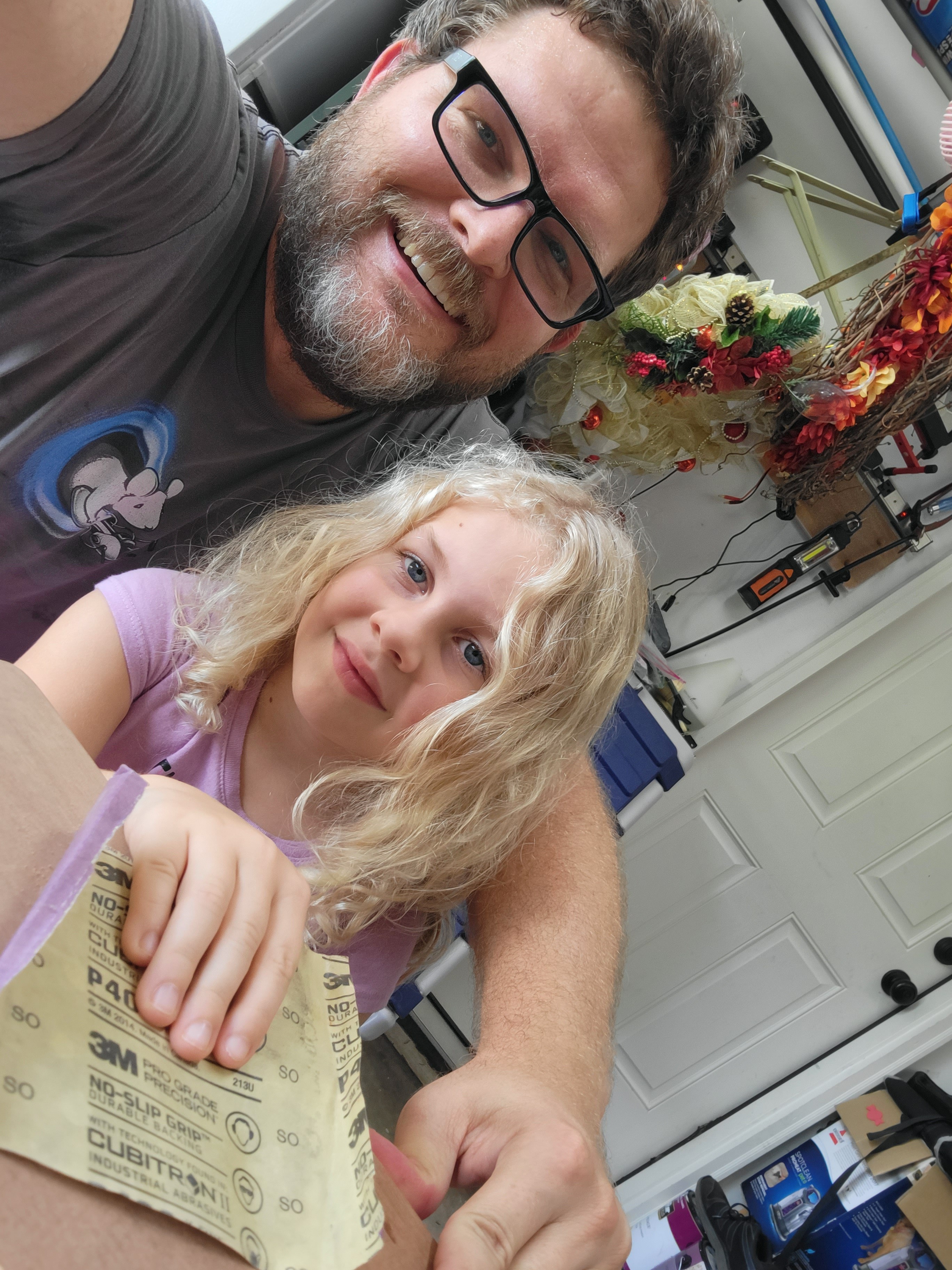
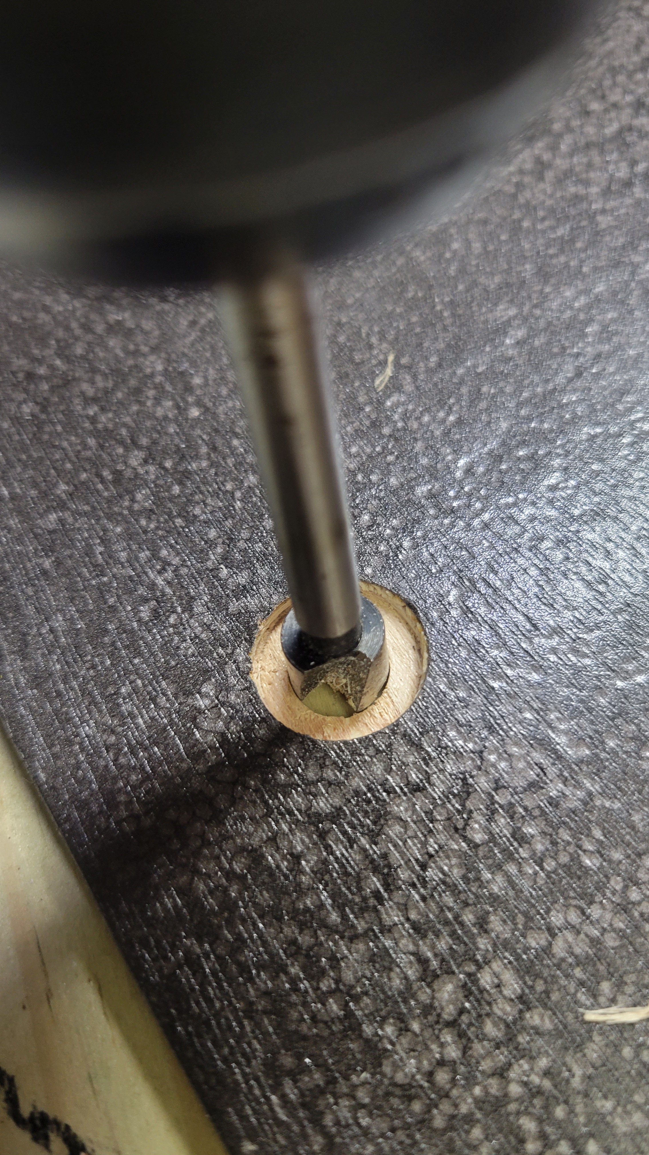
 Drilling holes with Daughter 1!
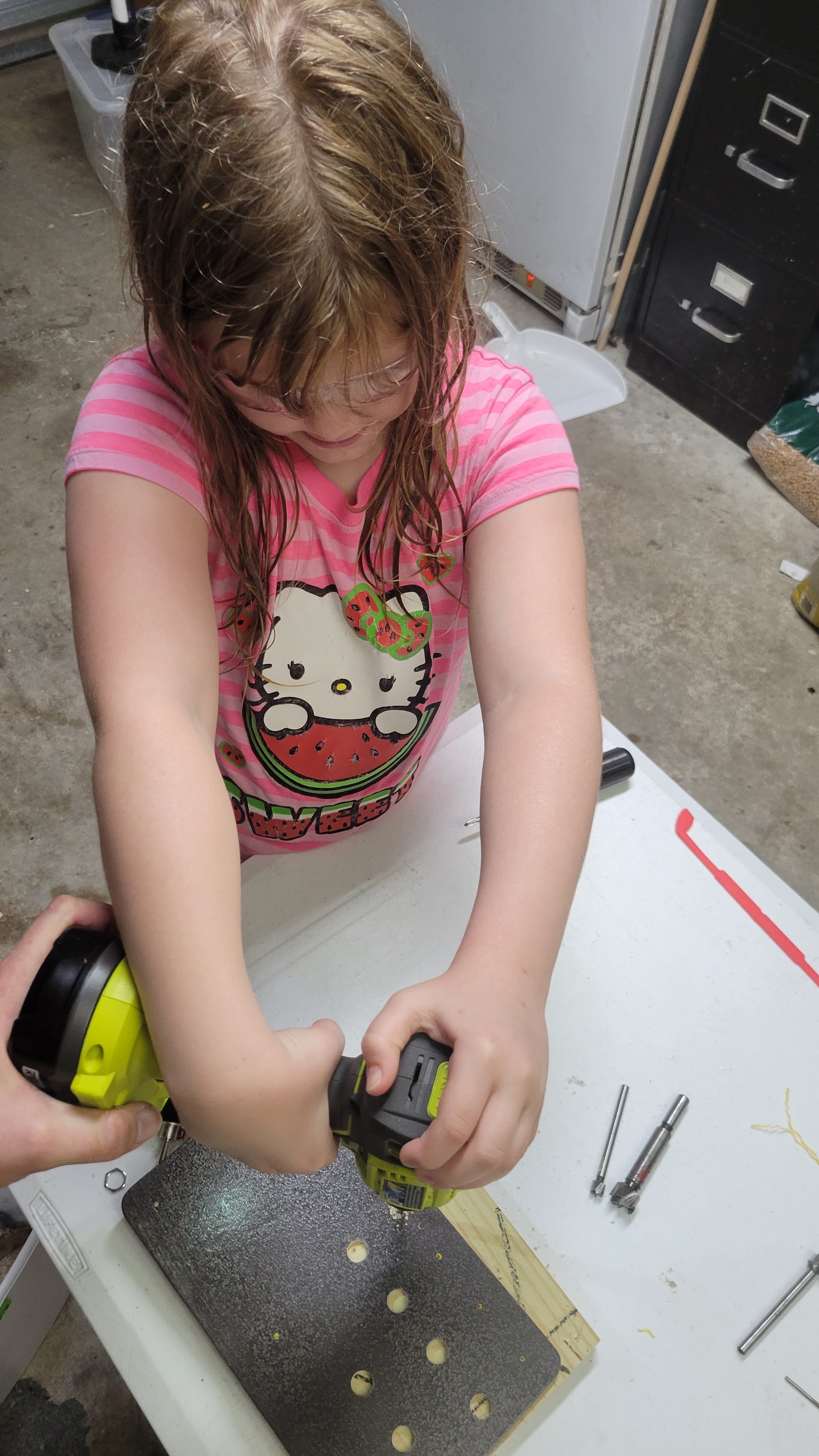
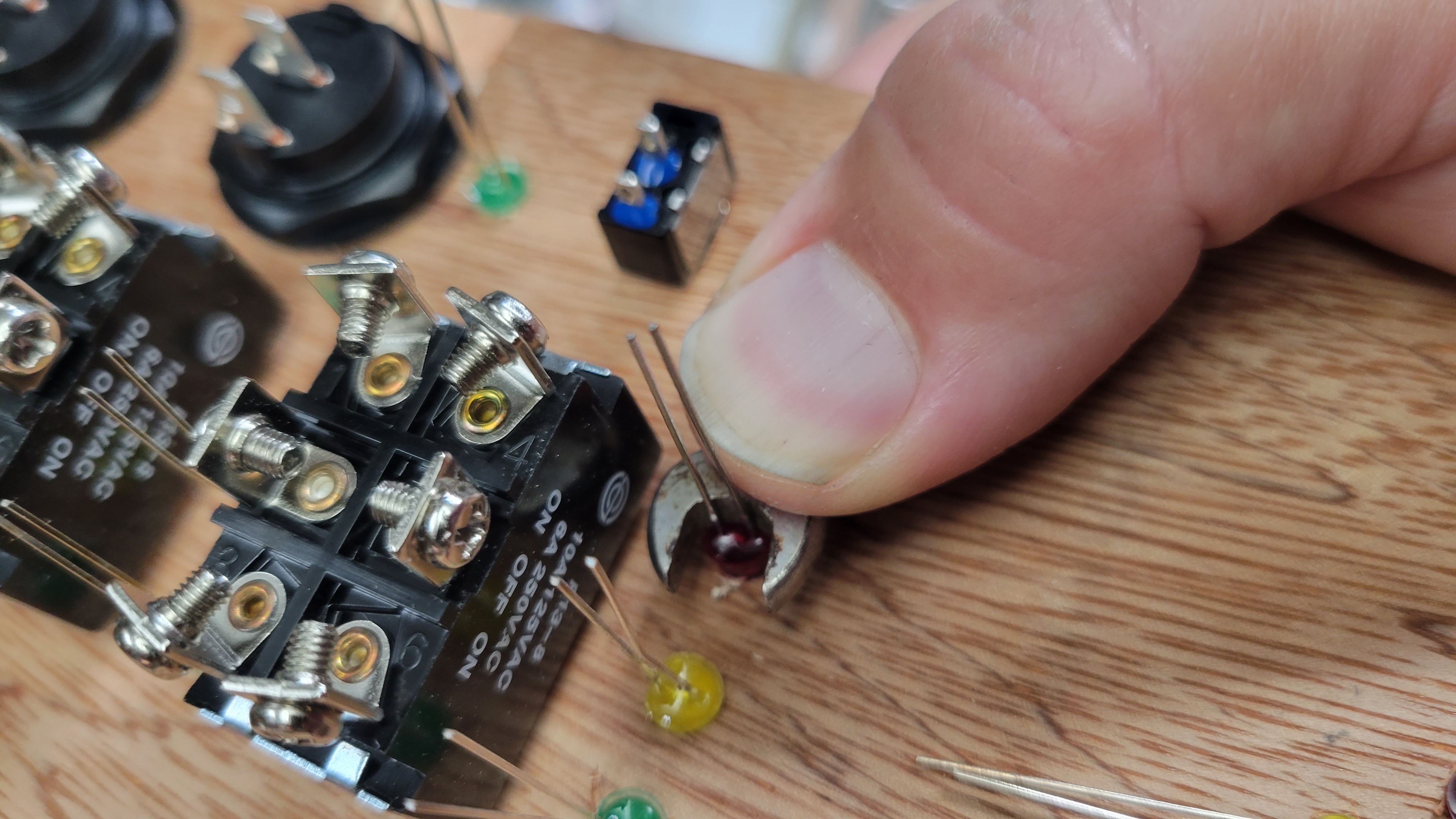
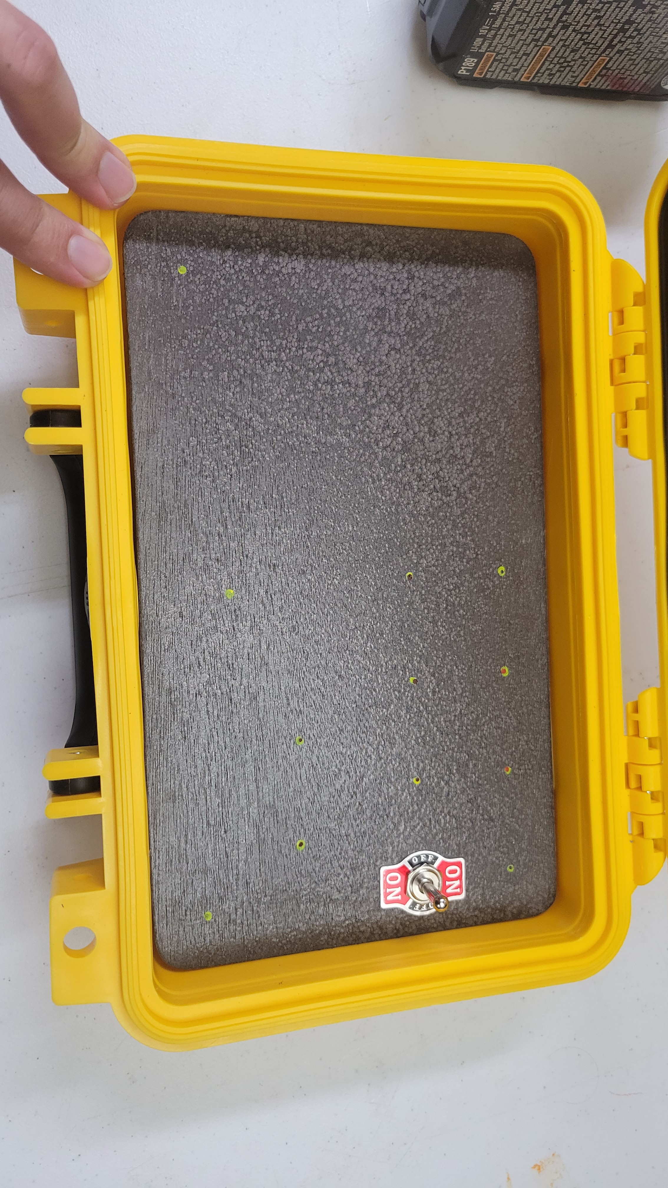
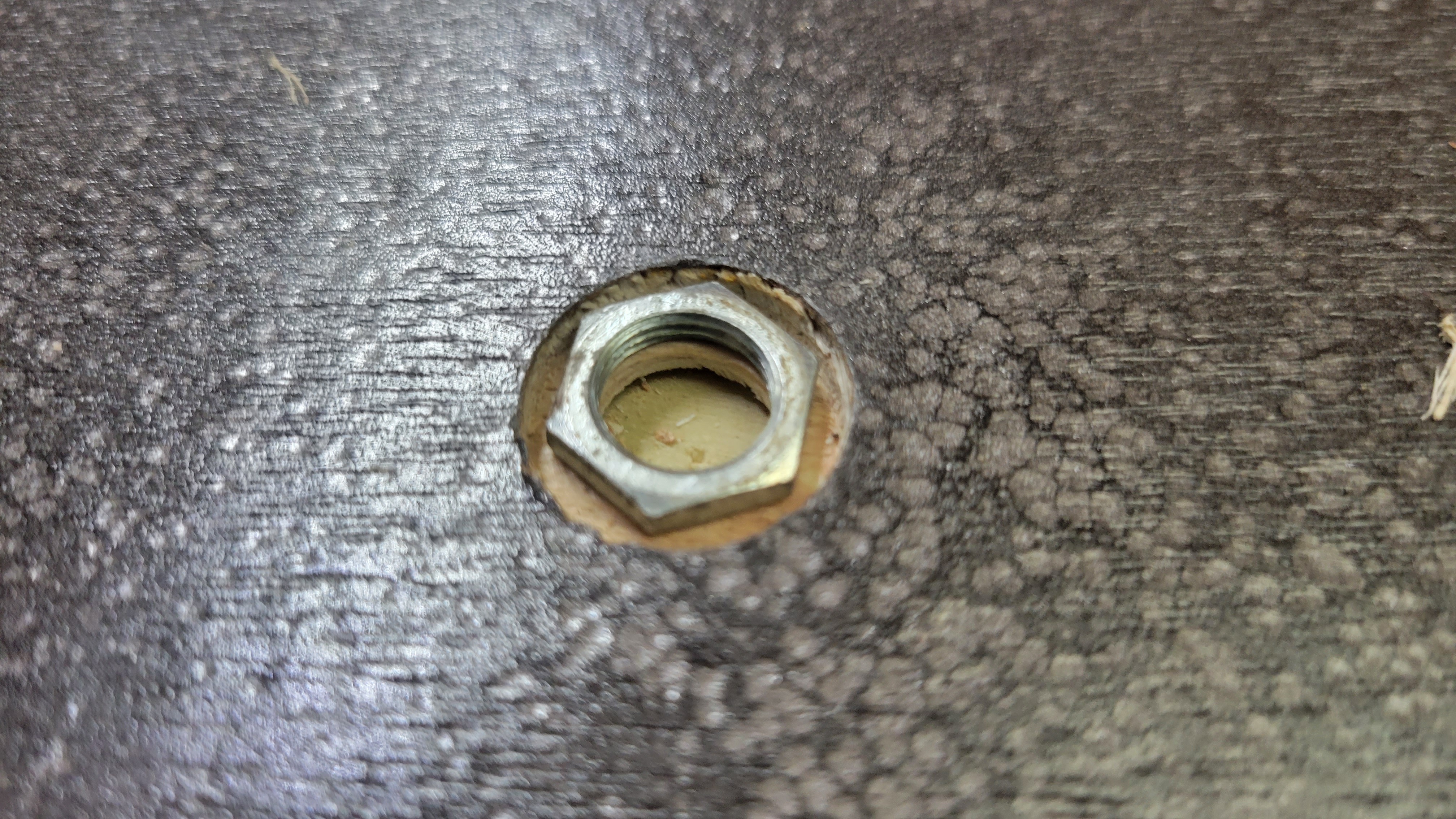 Almost finished drilling... just have to finish the corner pots and "Simon Says" buttons.
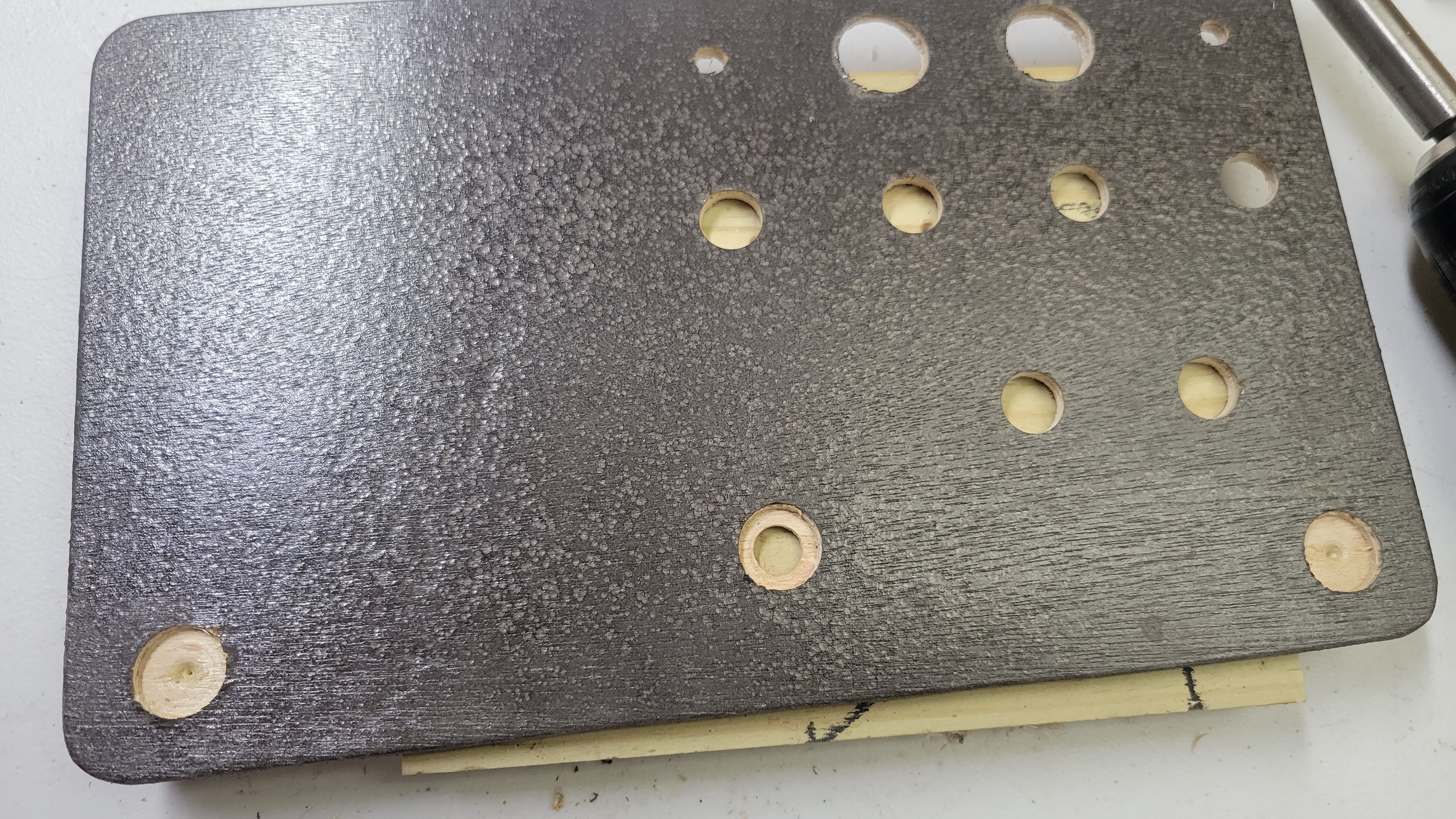


 Timo Birnschein
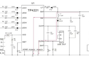
 andyhull
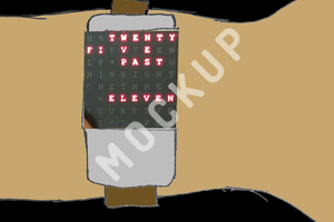
 PointyOintment
 Enrique
I heart this soo much! Soo many ideas?