 Daniel Porzig
Design Goals / Specifications
The design goals and specifications of the AutoDuct project are summarized below. The primary design goals (minimum viable product) are shown in bold.
- block unwanted airflow and outside noise in the decentralized ventilation systems
- achieve compatibility with the ventilation system "iconvent 160" made by the company "pluggit" (there are solutions from other suppliers on the market which are identical in design)
- automatically seal the vent system with the shutter mechanism, when the axial fan unit is not in operation
- when opened, provide a flow cross section larger or equal compared to the stock vent covers
- interface with the electrical bus of the stock ventilation system to receive power (+12V) as well as to identify fan activation (3.815kHz PWM signal with 5V amplitude). Primarily, achieve compatibility with the electrical bus of the ventilation system "iconvent 160" made by the company "pluggit" (there are compatible solutions from other suppliers on the market)
- control speed and rotation direction of a connected 12V axial fan unit via a PWM signal (3.815kHz frequency, 5V amplitude). Primarily, achieve compatibility with the fan unit of the ventilation system "iconvent 160" made by the company "pluggit". (there are compatible fans from other suppliers on the market, often fan units from EBM papst are used)
- enable remote control via Bluetooth Low Energy
- measure room humidity and temperature to enable automatic moisture control operating modes
- include capability for programmable ventilation events, up to 5 events per week day (requires memory for ventilation schedule as well as real time clock for time management)
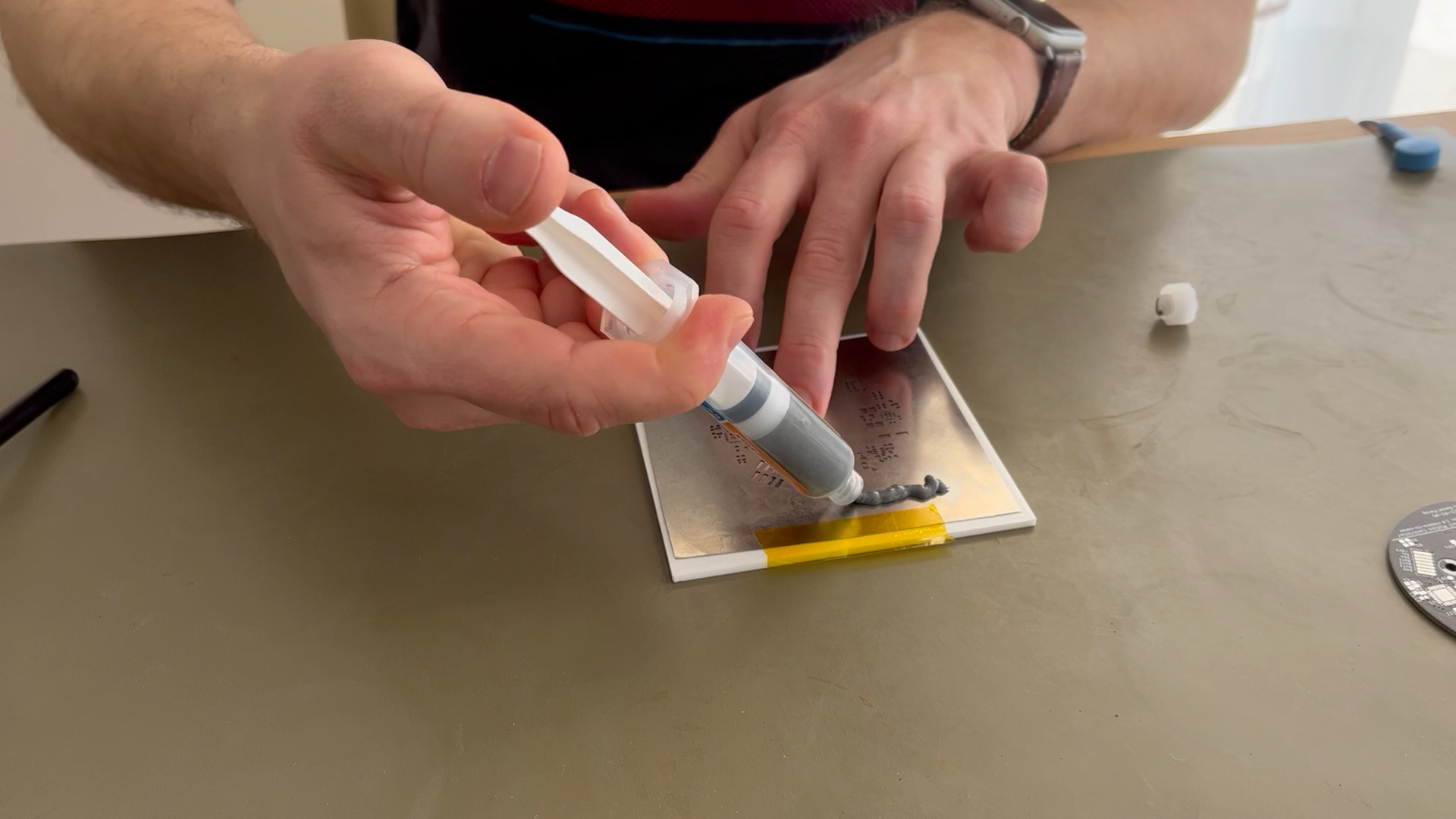
- use mainly 3D printed parts from PLA filament
- use a low cost geared DC motor to drive the actuator
- enable wireless firmware update
- enable integration into smart home ecosystems (using an additional wireless bridge unit)
- have a visible operating mode indicator on the front panel (LED)
- maintenance free operation
- allow installation of an (optional) dust filter disc on the back side of the shutter unit
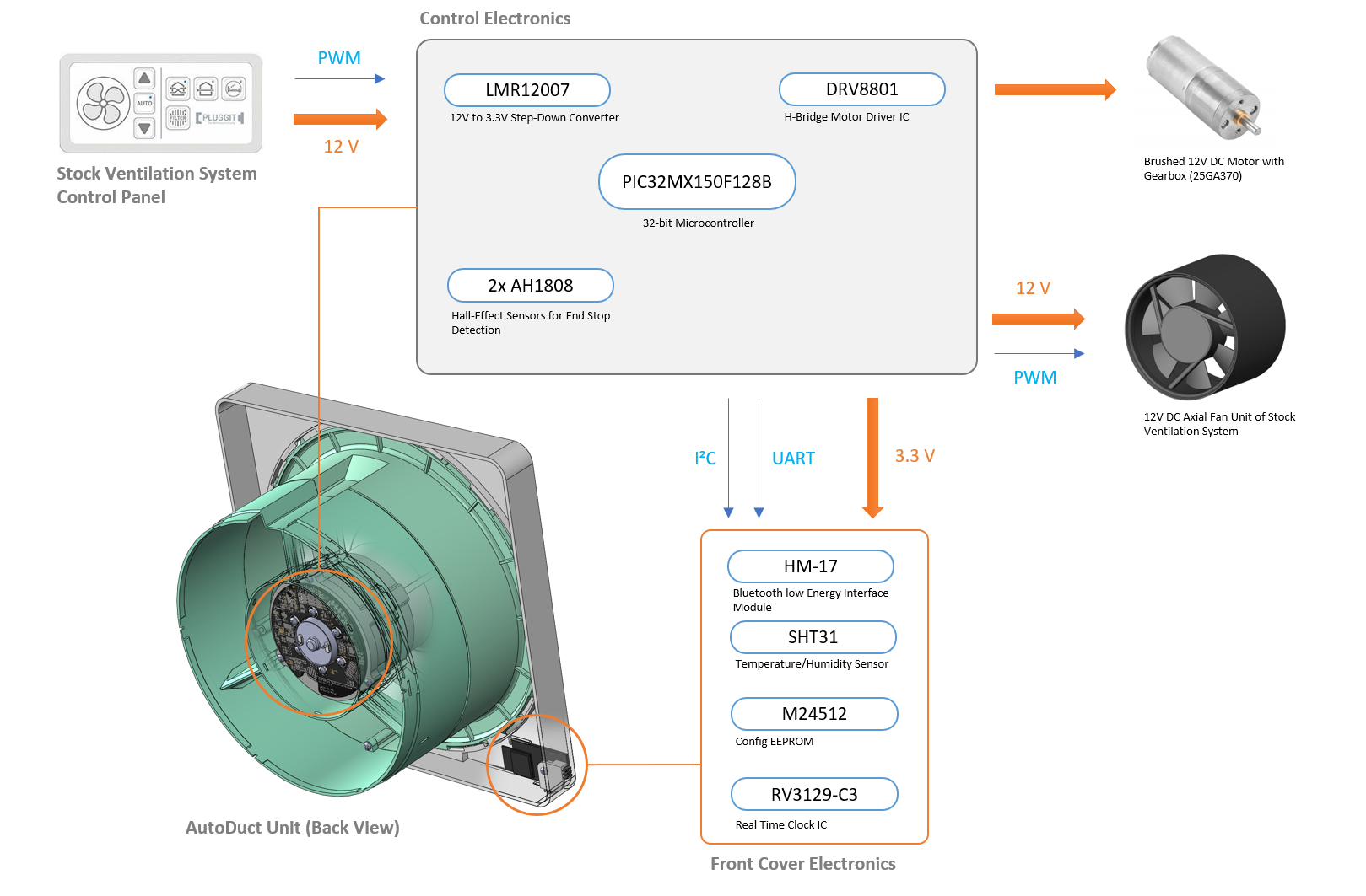
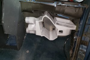
The picture below shows how the motorized air duct shutter integrates into the stock decentralized ventilation system. The stock vent cover of the ventilation system is replaced by the motorized shutter unit which electrically connects to the bus system and the axial fan unit.

Mechanical Assembly
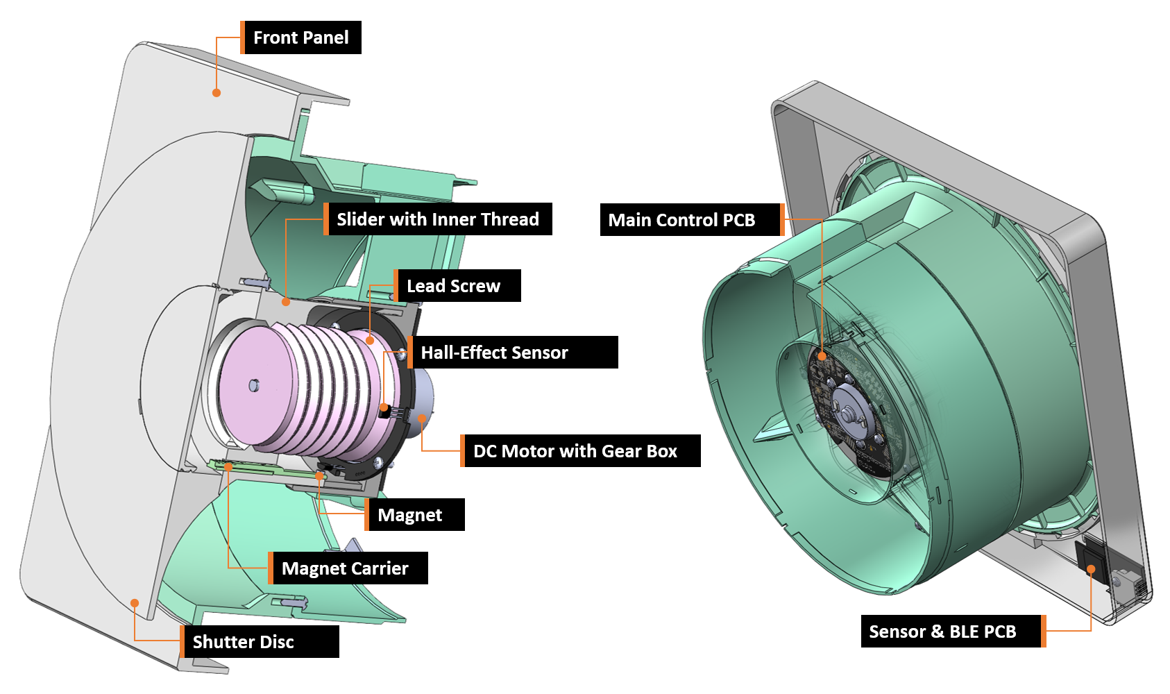
At the heart of this device is a mostly 3D-printed linear actuator which is used to open and close a shutter disc to prevent unwanted airflow. The 3D-printed leadscrew of the actuator is directly attached to a small brushed DC motor with an integrated gearbox.
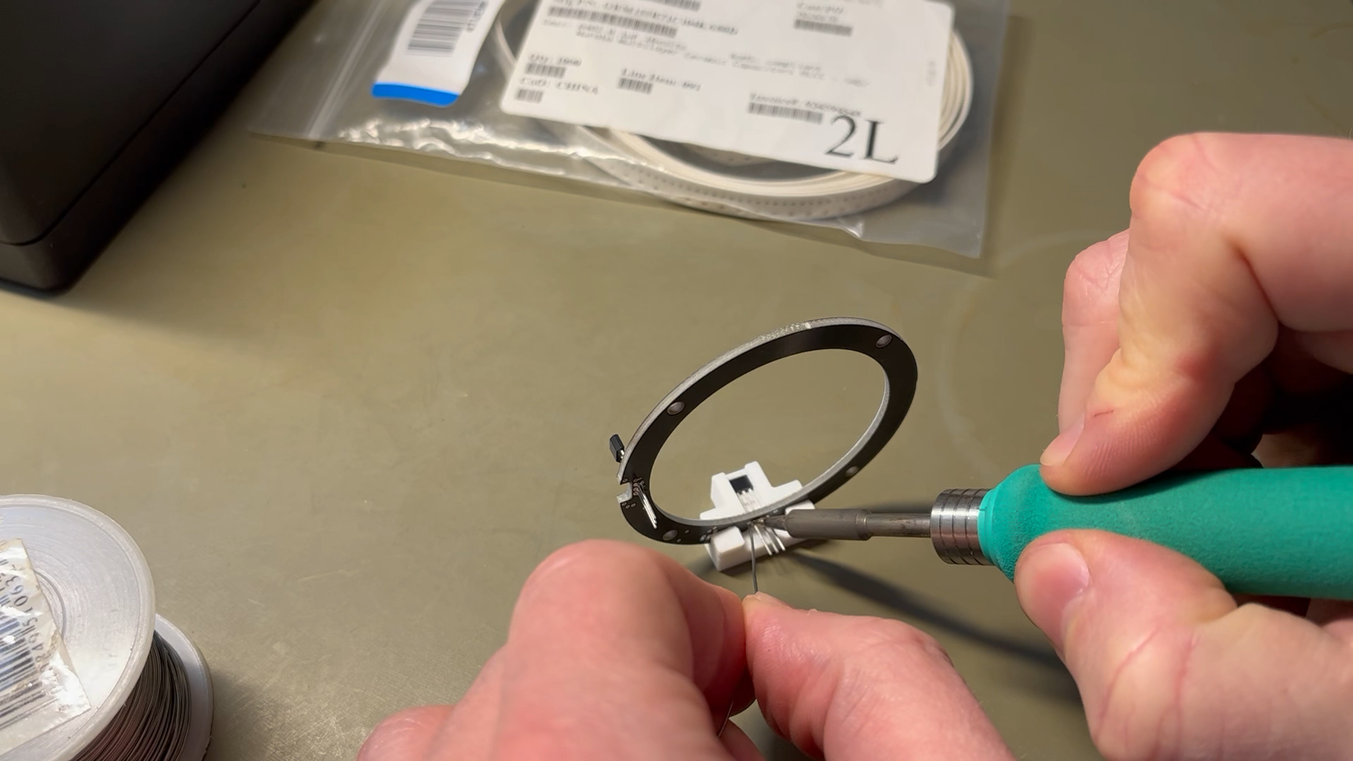
Integrated into the encapsulated actuator unit two hall effect switches on a separate ring-shaped PCB are used to detect the end stop positions (open/close) of the shutter mechanism in combination with tiny magnets. The axial position of these magnets can be adjusted to compensate for mechanical tolerances in the assembly.
Note: the actuator unit does not use any additional (ball) bearings to keep the BOM simple and material cost low. Axial and radial forces are solely absorbed by the 3D-printed linear guides and the integrated bearings of the geared motor. This could potentially reduce longevity of the assembly but has not been an issue while testing multiple units over more than a year now. Use of silicone grease is highly recommended.
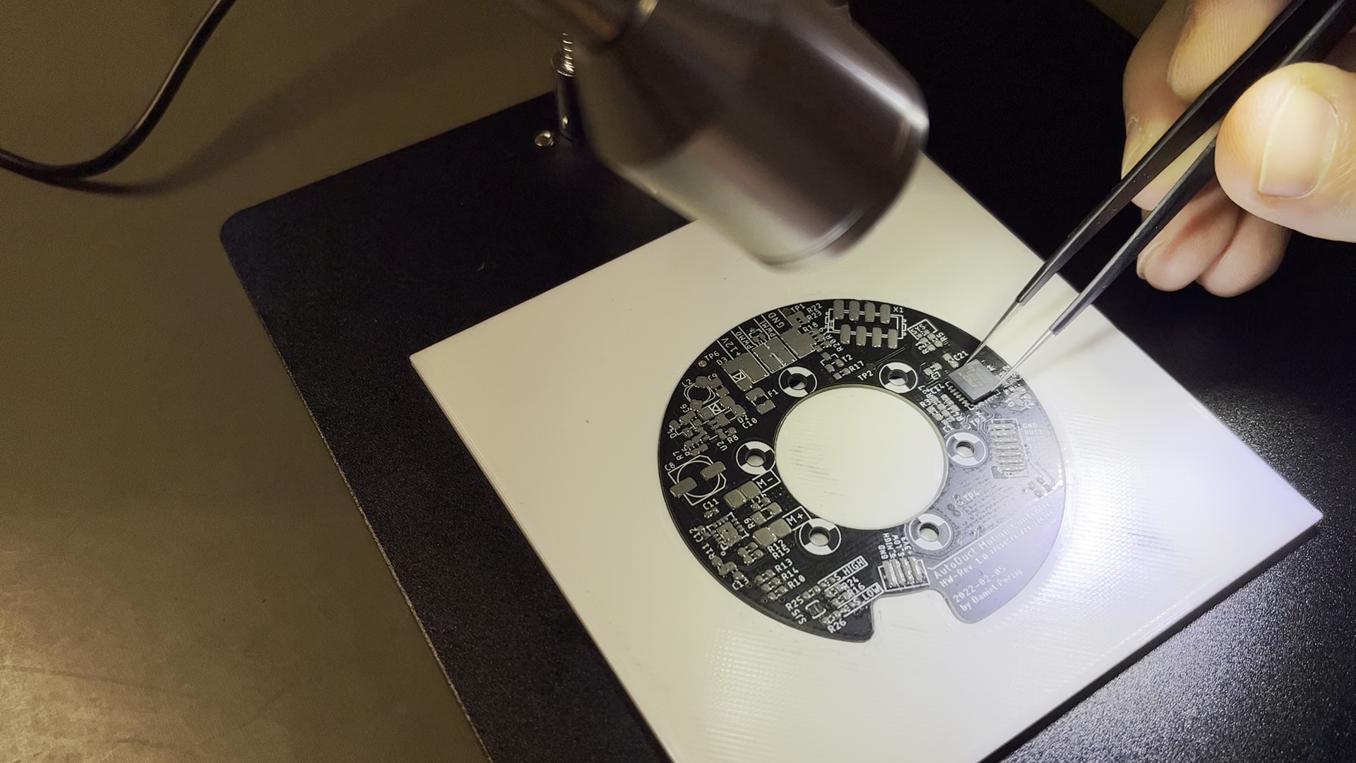
Electronics
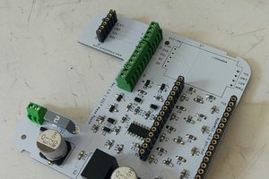
The electronics are based around a Microchip 32-bit microcontroller (PIC32MX), which might be a little bit overpowered for this project but was available from a previous project and has a neat footprint. The +3V3 rail is generated from the +12V bus by a step-down converter. The geared DC motor is driven by a dedicated H-bridge driver IC (DRV8801).
Behind the front cover of the assembly another small PCB is hidden. This PCB contains the Bluetooth low energy module (HM-17), a serial EEPROM, a real time clock (RTC) IC and a humidity and temperature sensor. User feedback is given...
Read more »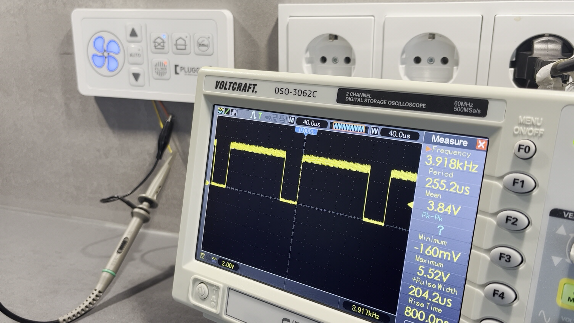


 looperTwentyThree
 Maya Posch
Great job! Could I translate your work to vietnamese and share to our community with original link include ?