The assembly process of the AutoDuct unit is shown in full detail in the following YouTube video. It is higly recommended to execute the assembly according to this video.
For reference all assembly steps are shown in the following sections as well.
2
PCB Assembly (control board and BLE daughter board)
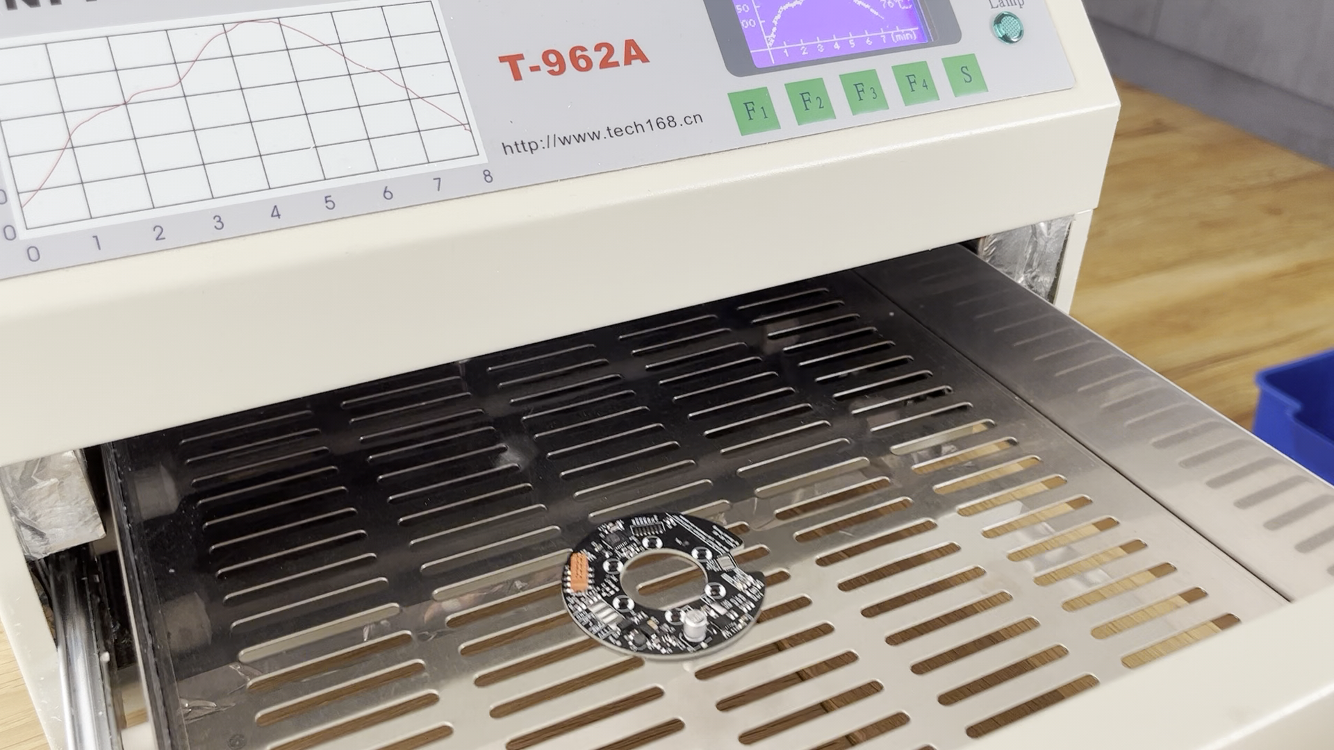
Apply solder paste on main control PCB and BLE daughter board using a solder paste stencil. Assemble parts on boards according to PCB schematics and BOMs. Complete the soldering process using a reflow oven or a hot air gun.
3
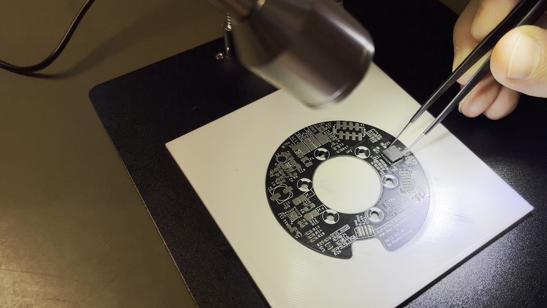
PCB Assembly (hall effect sensor board)
Use the 3D-printed alignment template for easy and precise alignment of the hall effect sensor and solder them in place. Install capacitors and flex cable.
4
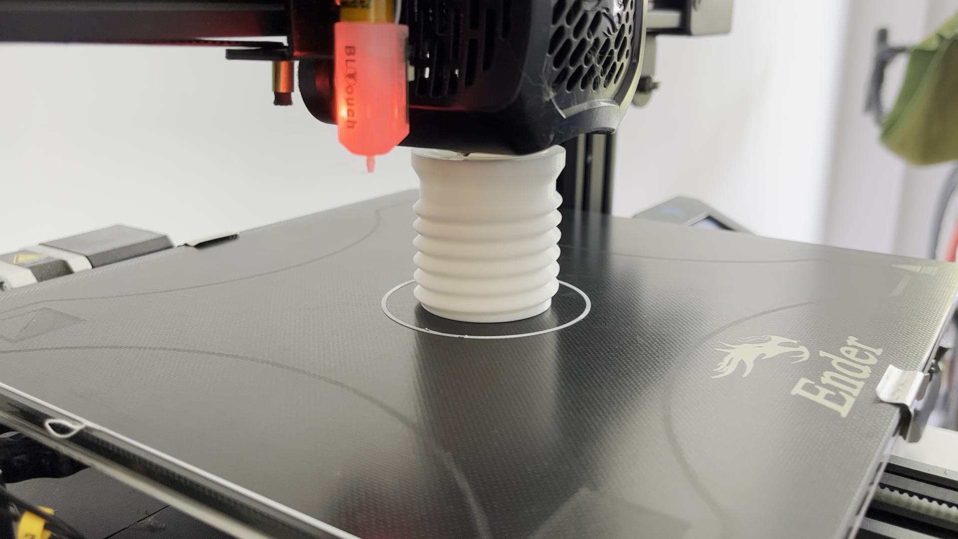
3D printing of components
Print all components with PLA or higher-grade material.
5
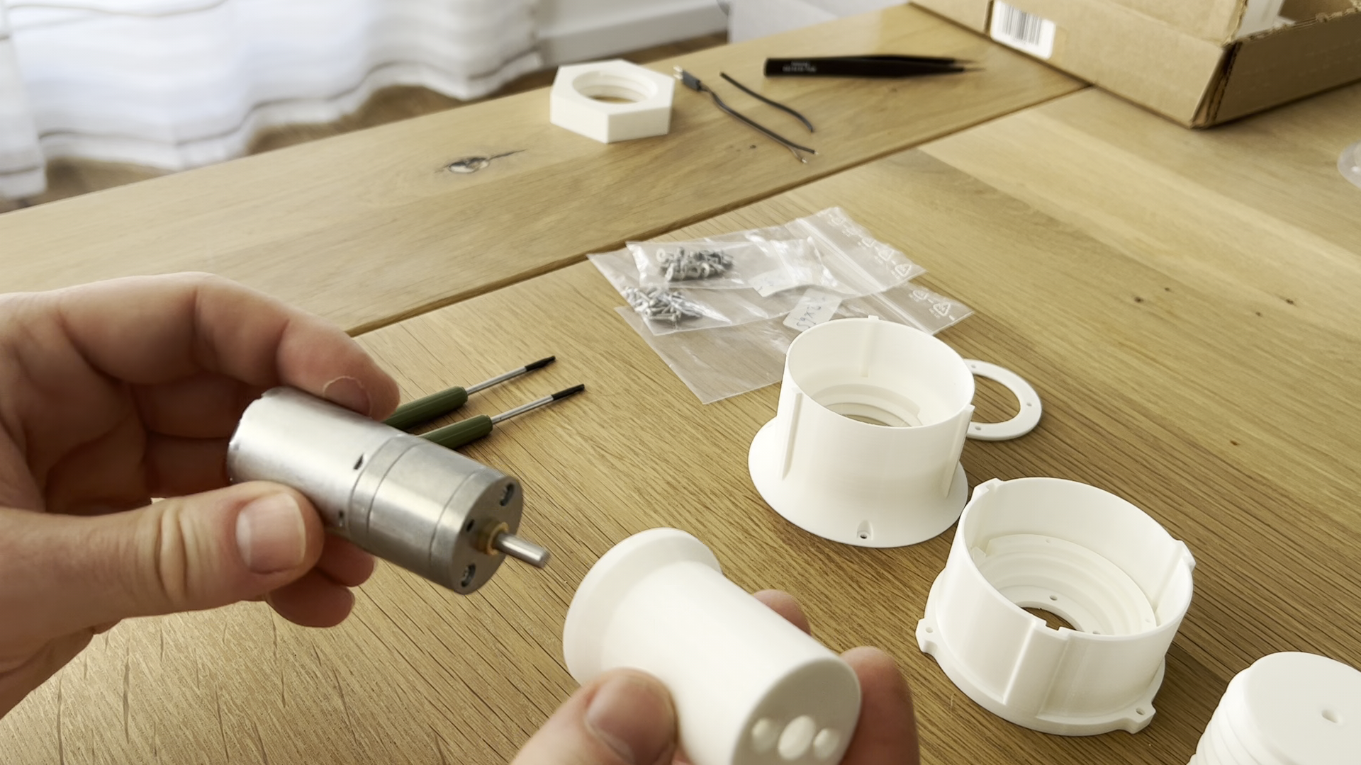
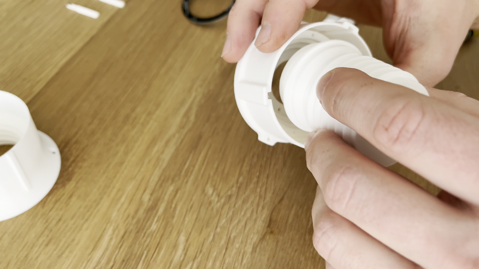
Linear Actuator Assembly
Insert geared DC motor into motor carrier, use 2x DIN7991 M3x5mm screws to hold motor in place.
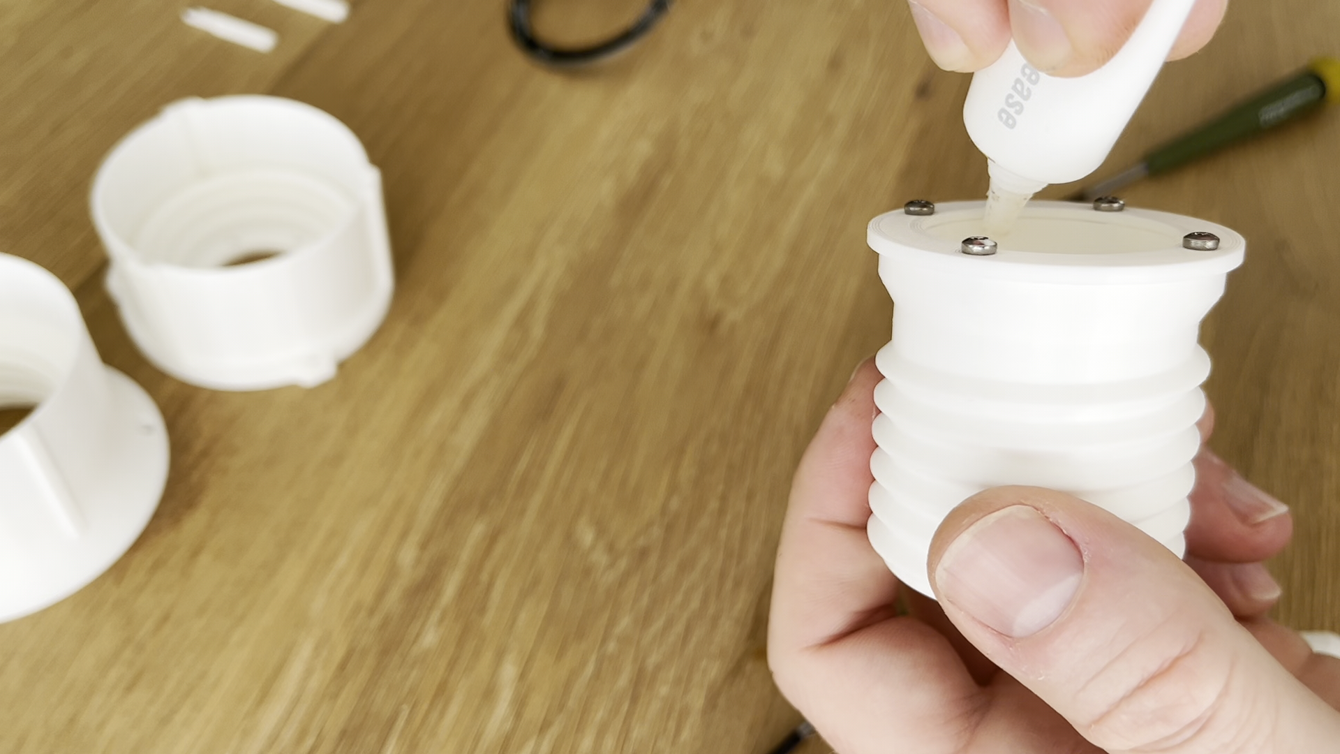
Mount thrust collar ring to leadscrew with 4x DIN7981 (diameter: 2.2mm, length: 6.3mm). Apply some silicone grease on the inner diameter of the leadscrew:
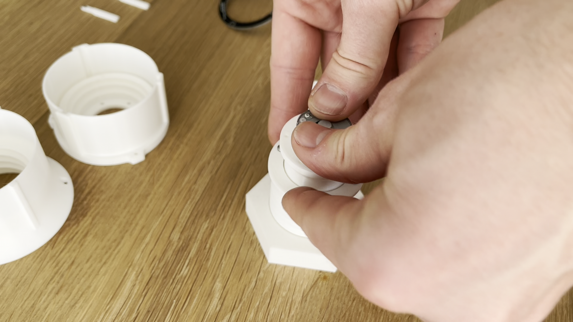
Push motor shaft into keyed hole of leadscrew (will require some force):
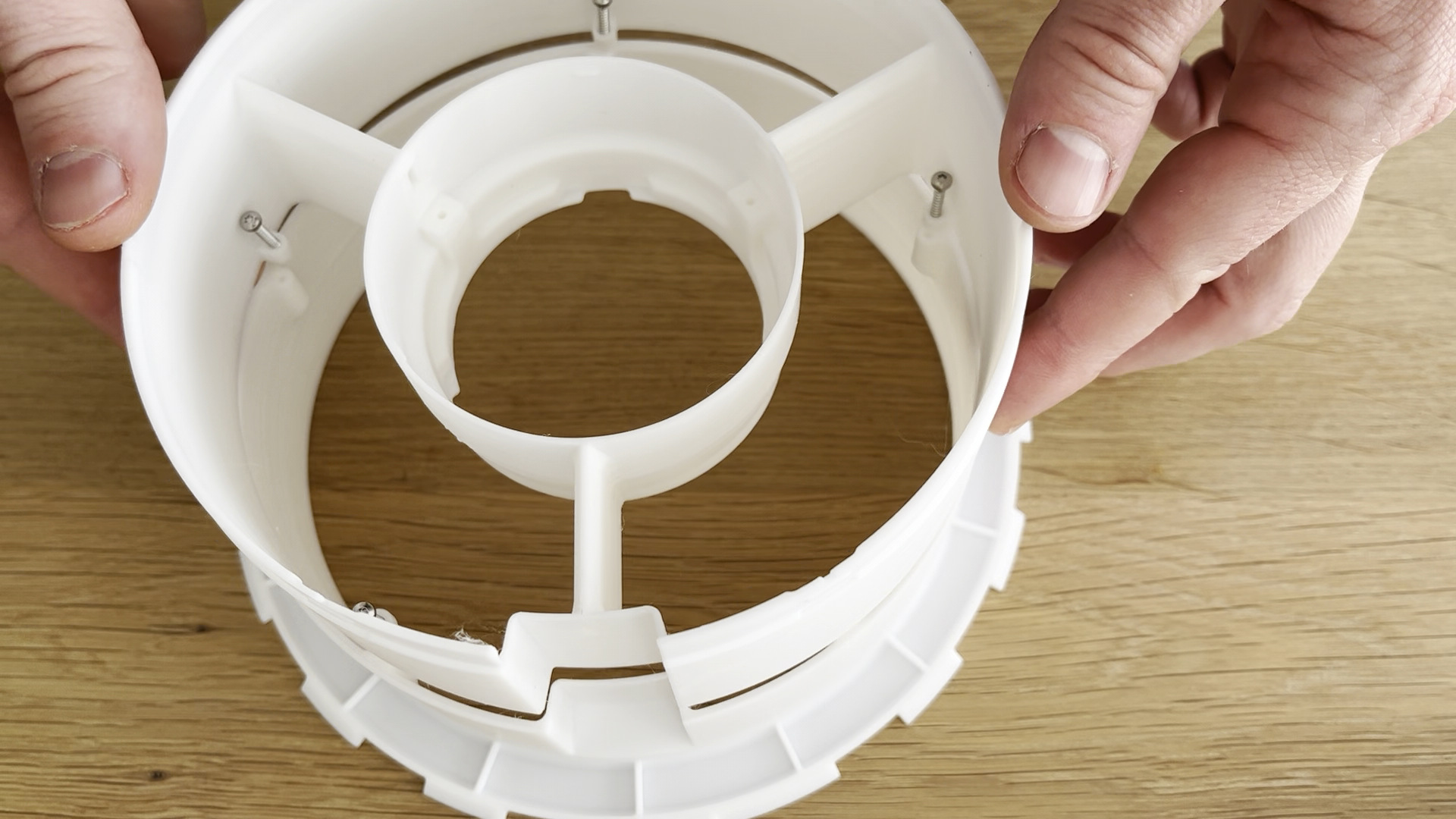
Insert leadscrew/motor assembly into centralizer component, make sure that holes in motor carrier are aligned with holes in centralizer:
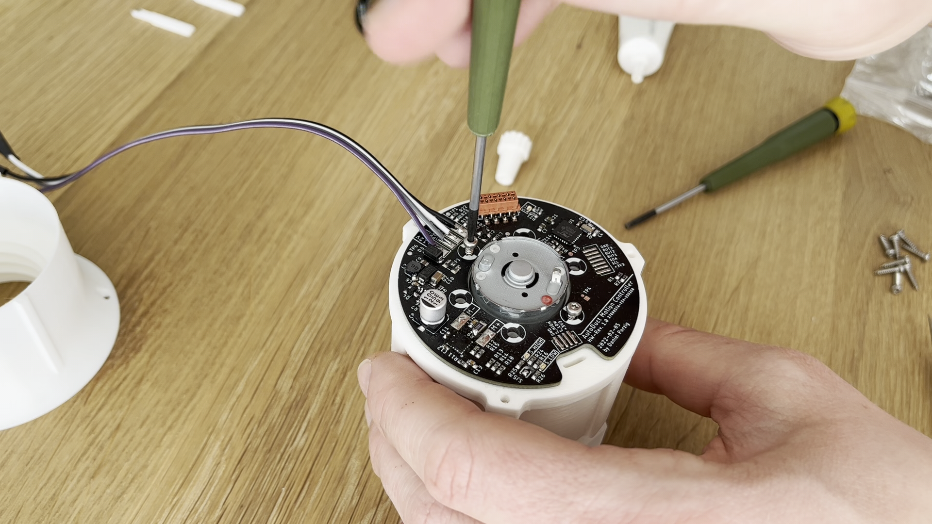
Install main control PCB on backside of linear actuator, use 6x DIN7981 (diameter: 2.2mm, length: 9.5mm) to bolt everything together:
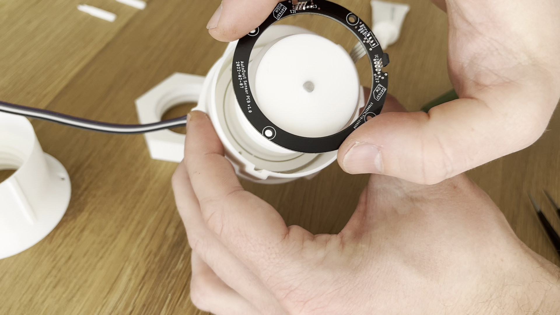
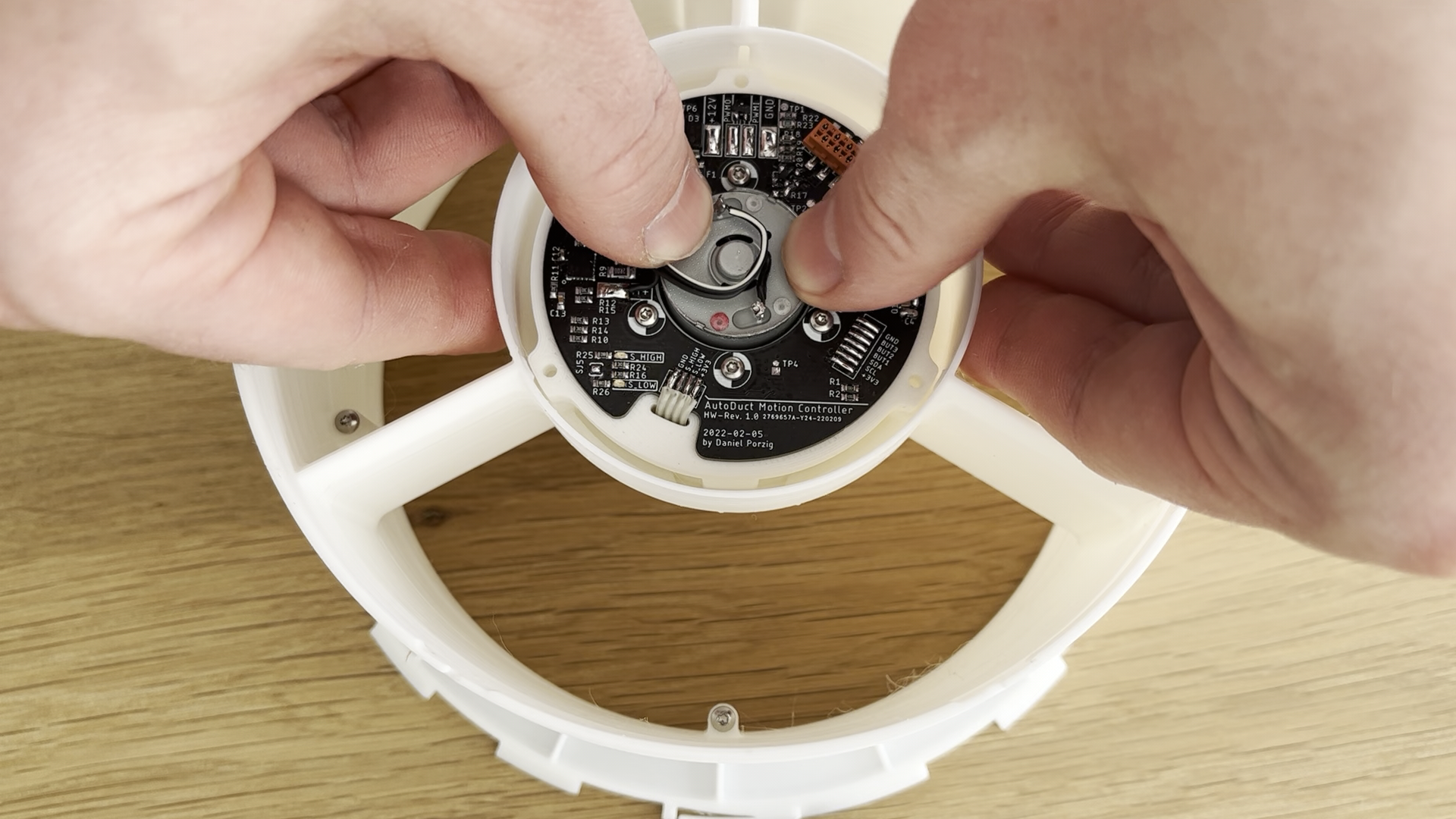
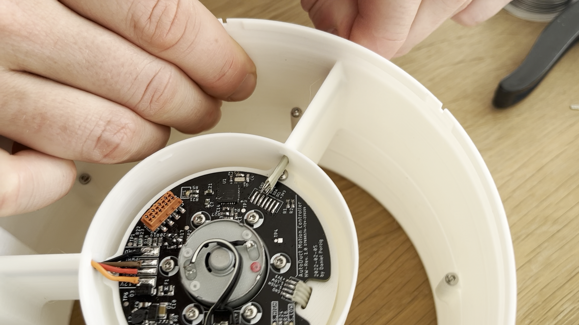
Install hall effect sensor PCB, make sure that the 4-pole flex cable is fed through the cutout in the centralizer component. Use 4x DIN7981 (diameter: 2.2mm, length: 6.3mm) to mount the PCB to the centralizer:
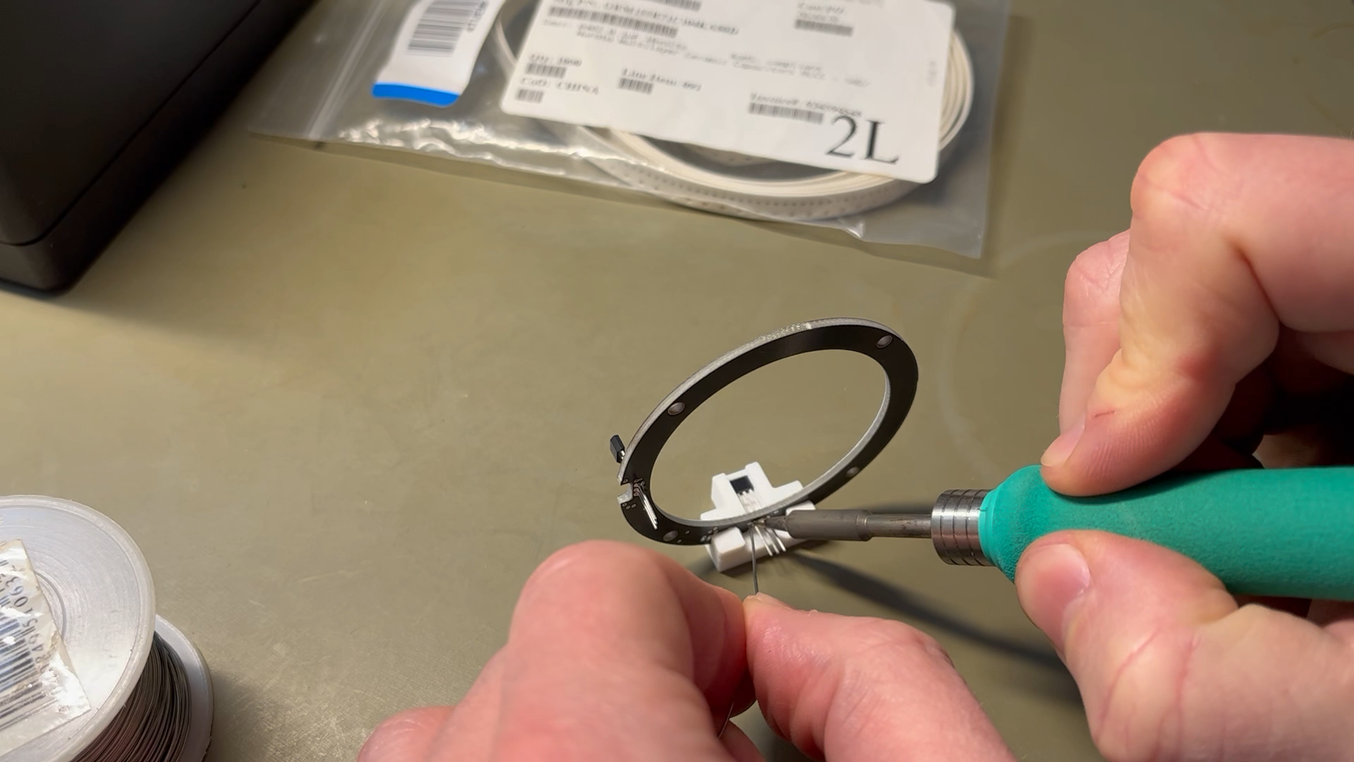
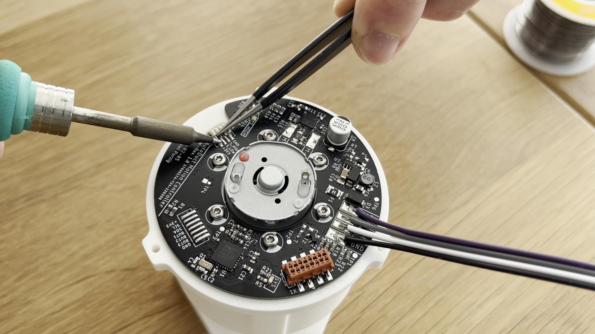
Solder the pins of the 4-pole flex cable to the corresponding pads on the PCB:
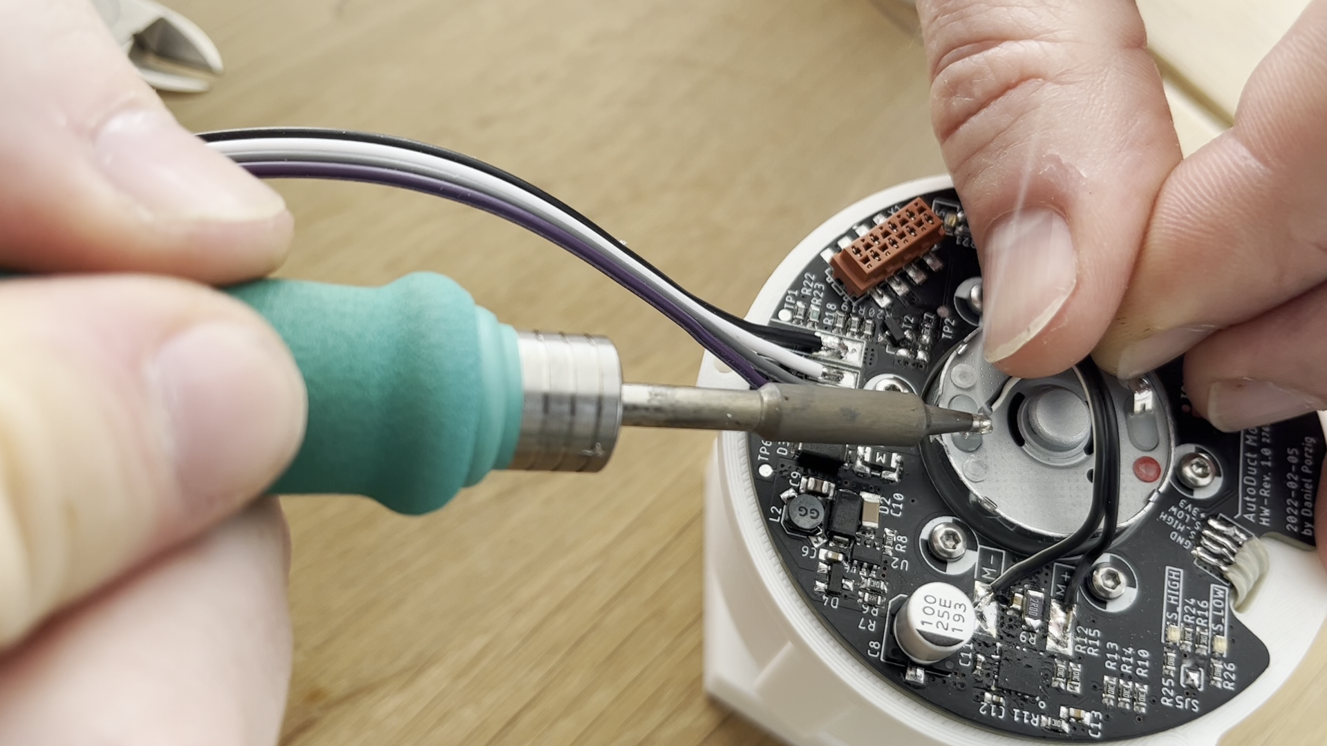
Add wire connection between DC motor and control PCB. Use AWG20 wire (or thicker). Red dot on motor solder connection marks positive terminal, which needs to be connected to M+ solder pad on PCB:
6
AutoDuct Body Assembly
Use 5x DIN7981 screws (diameter: 2.2mm, length: 9.5mm or 13.5mm) to mount wing ring component (upper) to vent adapter (lower):
Install the actuator assembly into the body. Make sure that alignment of PCB relative to the 3 wings is as shown (4 solder pads for external bus connection need to point towards the cavity in the OD of the body):
Use 3x DIN7981 screws (diameter: 2.2mm, length: 13.5mm) to bolt the actuator assembly to the wing ring component.
7
Install Wire Connections (Daughter Board and external Bus)
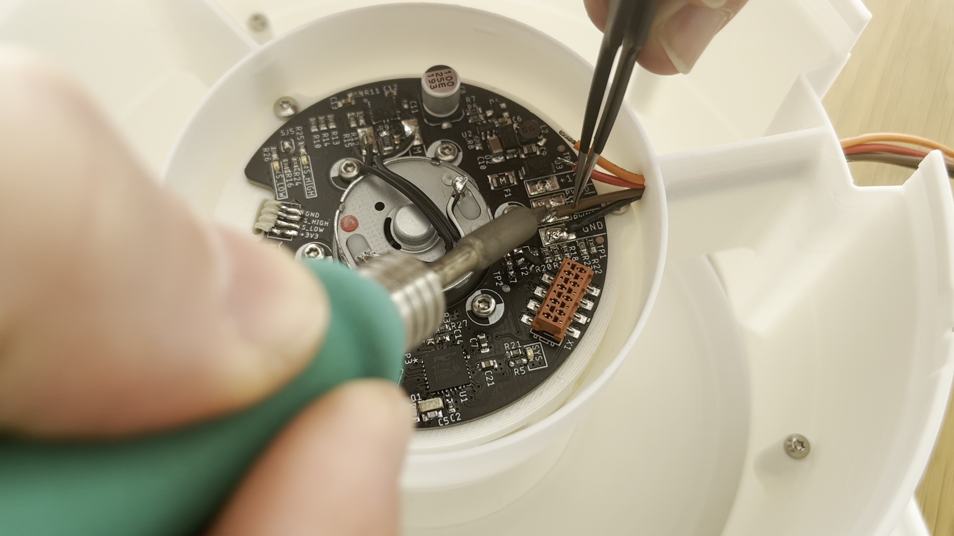
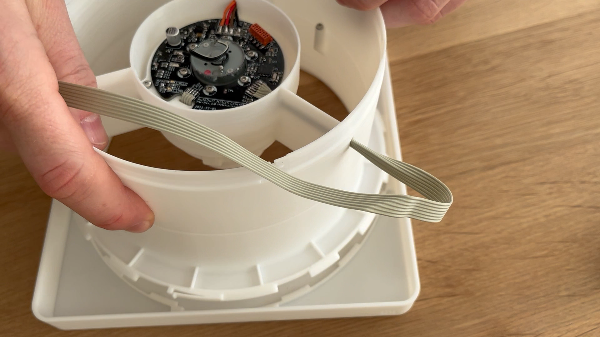
Cut 4 wires (external bus connection) to length (about 20 - 50 cm as required) and feed them through the upper channel in the wing structure. Solder wires to the corresponding pads on the PCB:
Cut the 7-pin flex cable to length (about 30 cm). Fold the cable as shown and feed it through the channel in the wing structure.
Solder the 7 wires to the pads on the PCB
8
Install Front Panel
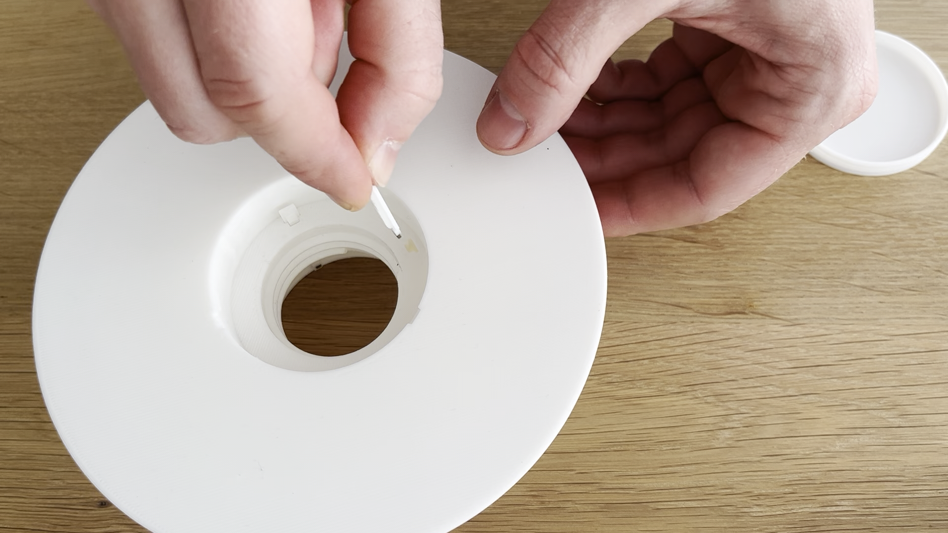
Insert the AutoDuct body into the front panel, make sure the 7-pole cable exiting on the OD points to the corner of the front panel with the slots for the humidity measurement.
Twist the body assembly CCW until the latch locks in place.
9
Shutter Disc Assembly
Use super glue to install the two magnets on the two magnet carriers (1x long, 1x short):
Bolt the slider component to the shutter disc using 3x DIN7981 screws (diameter: 2.2mm, length: 9.5mm):
Push the two magnet carriers into the cavities of the slider component, make sure about 5 mm of the magnet carriers still stick out of the front face of the slider. The short magnet carrier goes into the slot which is directly aligned with one of the 3 linear guides on the OD of the slider:
10
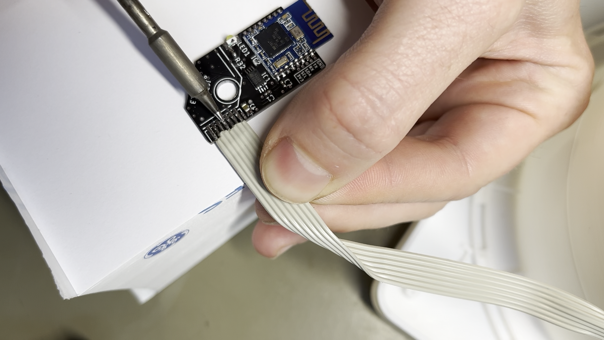
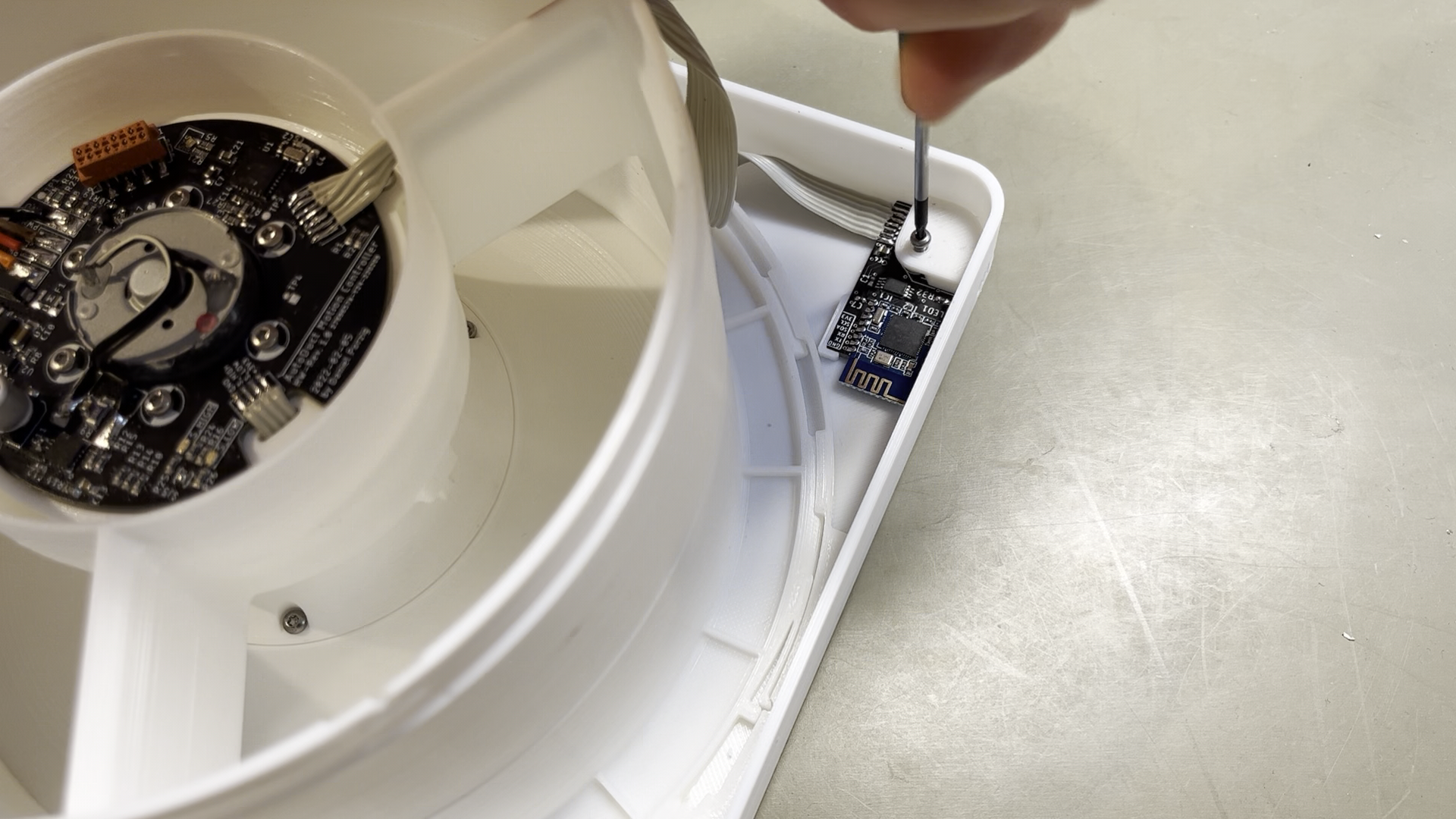
BLE Daugther Board Installation
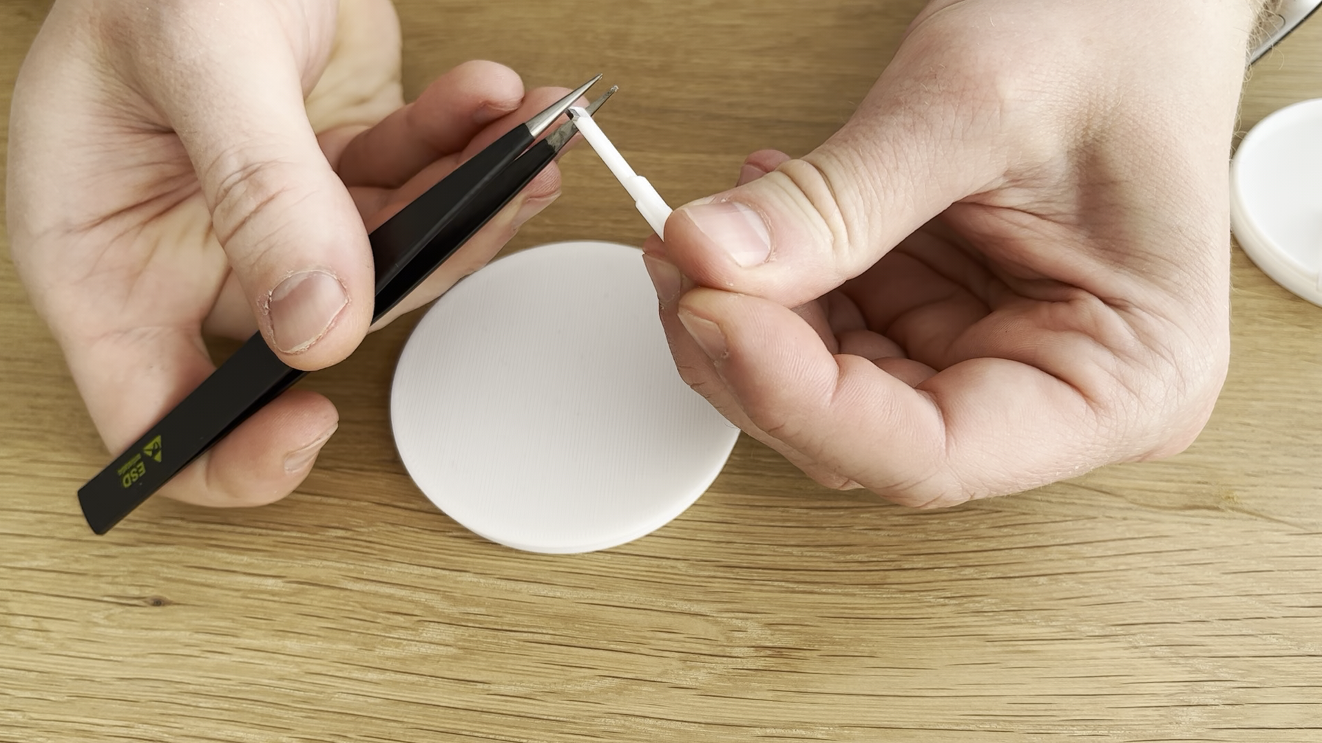
Solder the 7-pole flex cable to the BLE daugther board. Make sure the sequence of the individual connections matches the sequence on the main control PCB (ideally use a color coded flex cable):
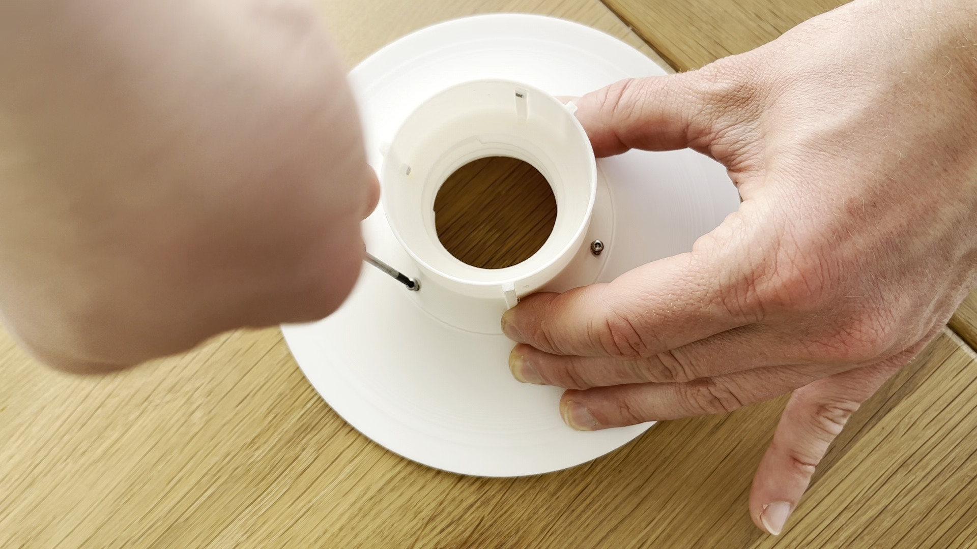
Install the daugther board in the socket on the front panel. Install the sensor cover on top of the PCB (fits firmly on the screw column protruding from the front panel). Secure the cover and the PCB with a DIN7981 screw (diameter: 2.2mm, length: 4.5mm):
 Daniel Porzig
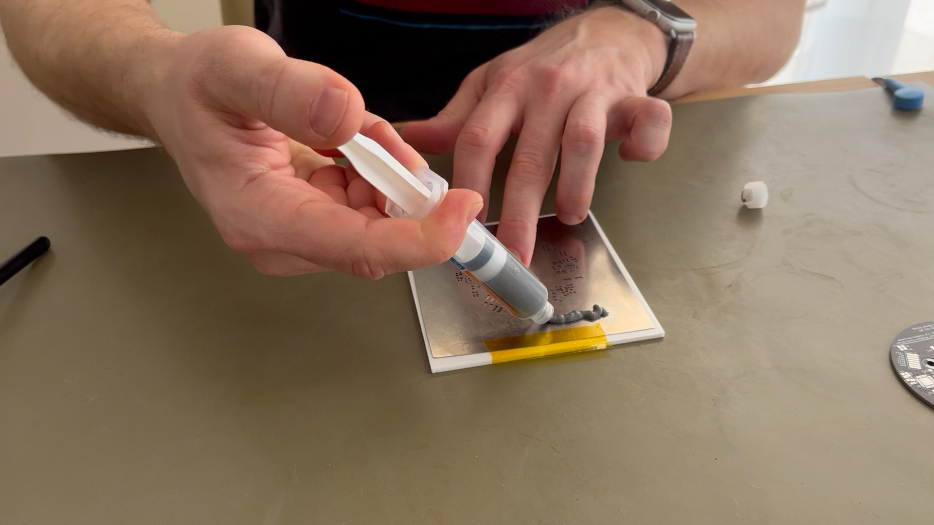
Discussions
Become a Hackaday.io Member
Create an account to leave a comment. Already have an account? Log In.