See also this YouTube video describing the way the system works:
This is my attempt at making a fast 6502-based homebrew computer. The current prototype is stable at 32.768MHz, which I'm happy with as it's in the same ballpark as 6502.org forum user "plasmo" has achieved in the past - I believe he may have had 40MHz working. 40MHz doesn't work for me, and I haven't tried any frequencies in-between yet.
Full schematics for the current prototype are linked below and in the "Files" section, and I will see about providing code and PCB designs when I find the right way.
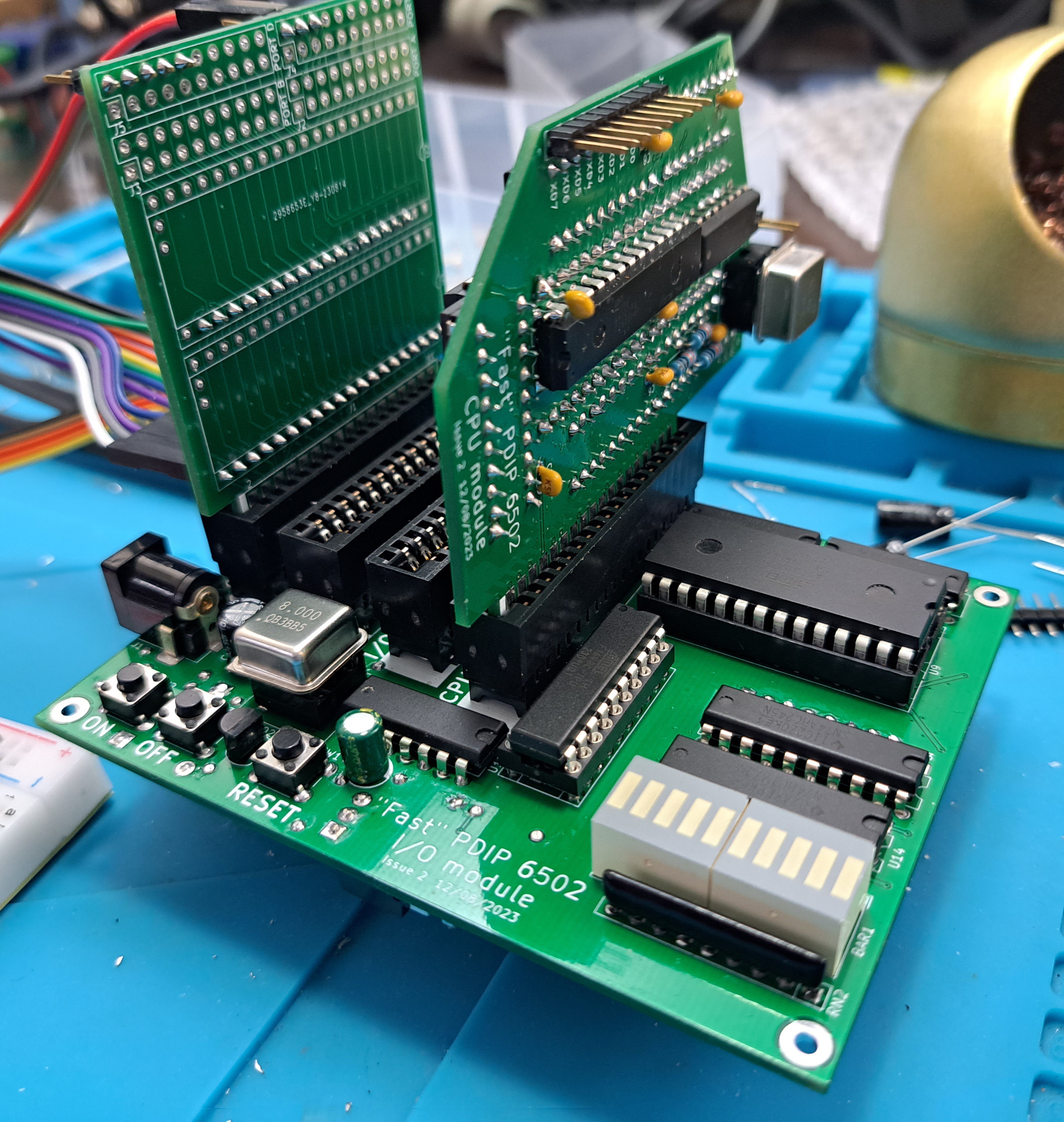
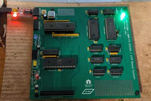
Here's what the system looks like fully assembled, with the CPU module present and an expansion card in place. I used a modular design so that I could iterate on modules individually without having to rebuild the whole system each time, and add more modules at later dates.
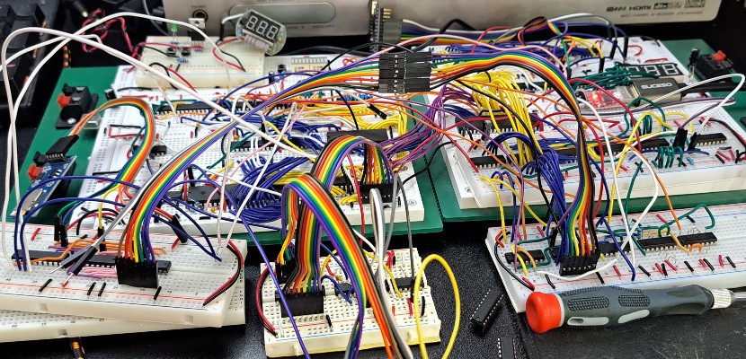
And here's the 25.175MHz breadboard prototype, with more work-in-progress - see below for more details on that:
Concept
I've built several 6502-based computers over the years I've been learning electronics, but my focus has never been on clock speed except where it was necessary - I've been more interested in designing peripherals, such as video output cicruits or floppy disk controllers. Nevertheless I've had a design in the back of my mind for this, and I decided to flesh it out and build it.
The main principle is that the only bit that really matters is how fast the CPU can run from RAM, so we connect them together as directly as possible and don't accept any compromises for the sake of other components. While many similar systems tend to run code from ROM, this is not essential as you can generally just copy the code to RAM before running it - and in any case you can still run code from ROM, just more slowly. Similarly, I/O operations are rare compared to RAM operations, and it doesn't matter much how slow they are.
In practice this allows the computer to run at over 25MHz on a breadboard, and over 30MHz on a PCB, and although I/O operations are slower, in practice they are so rare they don't affect the average clock speed much.
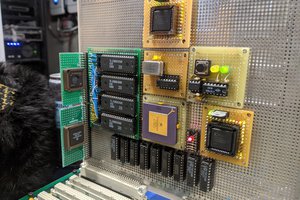
CPU Module
 |  |
Schematic: https://cdn.hackaday.io/files/1926308241481920/6502fast3cpu-iss3-schematic.pdf
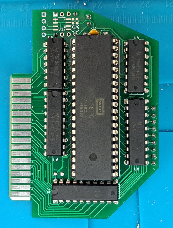
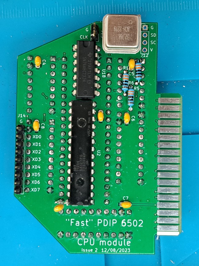
Removing ROM and I/O from being core considerations enables us to design a tighter core system consisting of the CPU and the RAM directly tied together with a fast clock. This CPU module is essentially a self-contained 6502 computer system, and mostly runs on its own, but lacking non-volatile storage, it can't actually boot itself. To communicate with ROM and I/O peripherals then, we send a signal to an I/O module, and hold the CPU clock high - pausing the CPU mid-instruction - until we get a response saying the operation is complete. The CPU's buses are buffered from the I/O module using bus transceivers, to ensure that the core CPU/RAM combination is as unencumbered as possible in normal operation.
I/O Module
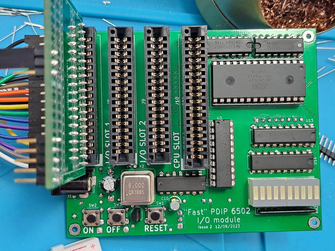
Schematic: https://cdn.hackaday.io/files/1926308241481920/6502fast3io-iss2-schematic.pdf
The I/O module handles all operations other than fast RAM access. Examples of I/O operation include accessing a 6522 VIA's control registers, setting an LED state on a debug port, sending a byte over a serial link, or reading a byte from ROM. It forms the bulk of the system, and is architecturally very similar to any typical 6502-based computer system - just without direct connection to a CPU.
It receives the "IOWAIT" signal from the CPU module, along with the address and data bus states, and performs the usual type of address decoding to decide which I/O device (or ROM) should respond to the request. The device in question then needs to do that based on the address and data bus states. When the device is ready, the I/O module can send the "IOREADY" signal back to the CPU module to unpause it and let it carry on.
In theory we can wait for different...
Read more »

 Dave Collins
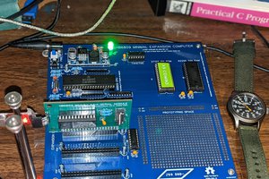
 Jason Westervelt
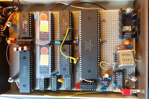
Have you checked out the Si5351A as a clock generator? Somewhat more flexible that the generator you are using. They are cheap on AliExpress.