 teardownit
Hard. Descriptions, instructions, diagrams.
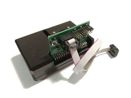
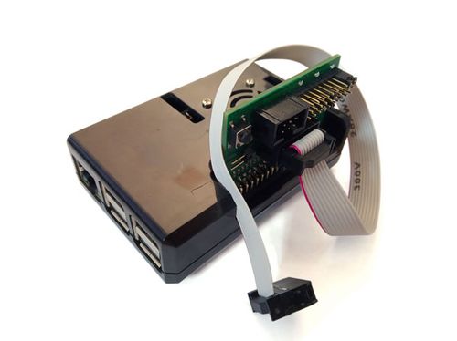
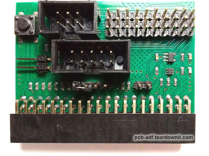
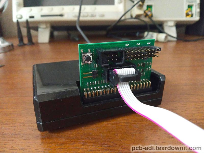
- Unified extension board for Raspberry Pi microcomputers. The board is designed primarily for programming and debugging microcontrollers and FPGAs. Still, it can also be used as an interface for various devices.
The board has built-in elements:
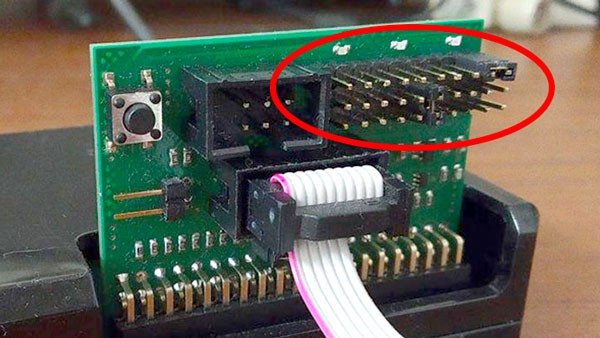
· Universal connector for our target system adapters
· A connector for connecting buttons, foot buttons, and pedals for mass production
· Multicolor LED indication for displaying modes and stages of device operation, also for mass production - Our adapters for connecting various microcontrollers, FPGAs, and target systems based on them to a unified extension board.
- Complete electronics kit for converting serial ovens into a solder paste reflow oven (sensor and power parts).
- Ready-to-assemble solder paste reflow oven.
Soft. Deb-repository of ready-to-use instructions, applications, and out-of-the-box solutions
- Software packages and scripts for working (programming, verification, debugging) with microcontrollers, FPGAs, and target systems based on them via a unified extension board.
- A script shell for organizing an automated, repeatable process for programming several identical microcontrollers, FPGAs, and target systems based on them via a unified extension board.
- Applications and script packages for PCB assembly:
· Navigation package for mounting SMD components on PCB.
· Packages for preparing and cutting Darcon stencils for solder paste application.
· Package for controlling solder paste reflow oven electronics kit
 James Fossey
 electrobob
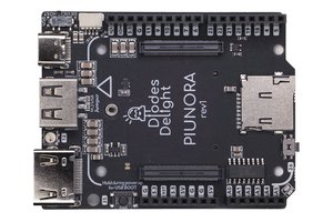
 timonsku
 Freesearch