 Lithium ION
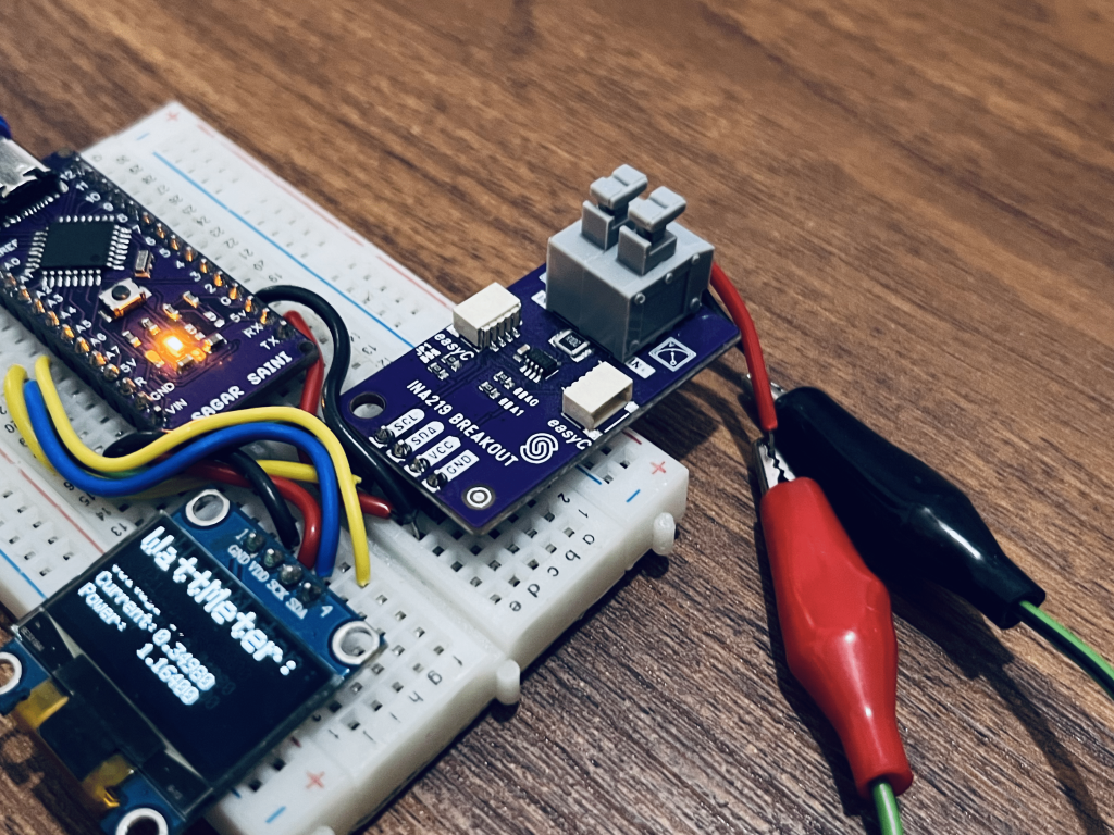
Another Wattmeter project is here, but this time everything is controllable digitally. We are using the INA219 as a digital device that allows the measurement of current, voltage, and therefore power. Simply, connect wire serial through this device and it will give all the information provided via I2C communication. It is very simple and reliable to use. It has a jumper for making changes to the I2C address so you can connect more than one INA219 to a single microcontroller.
The maximum current of the measurement is determined by the shunt resistor found on the plate which is 0.1ohm (± 3.2A). Yes, it can measure the power in both directions! If you want to measure other currents or smaller currents more precisely, check out the datasheet to change that resistor. The maximum voltage that can be measured is 26V.
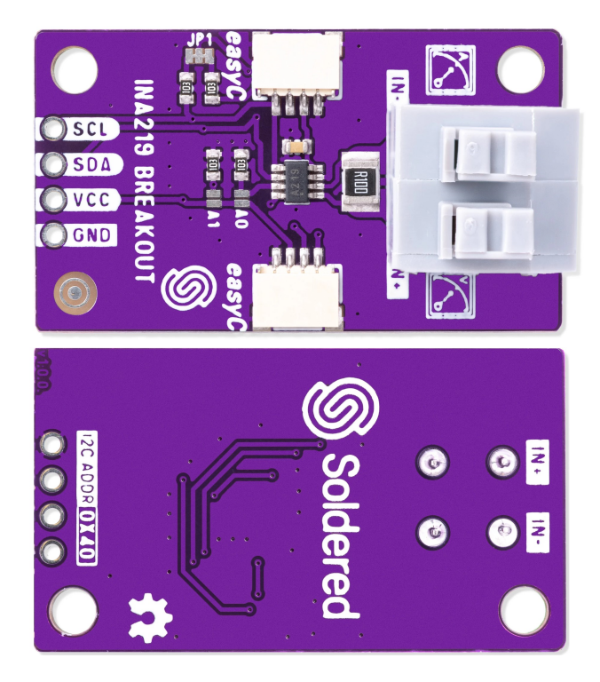
INA219 sensor:
This INA219 current sensor comes with a lot of modes and configuration settings which can be adapted as per requirements. With this Digital IC we got precision over a simple shunt amplifier. It also surpasses the ADC resolution of Arduino. I have a unique Arduino board. I designed my own PCB. You can order the same from PCBWAY for just in $5 for 10 PCB.
Features:
Supply voltage to INA219 : 3V - 5V
Maximum measuring voltage: 26V
Maximum measuring current: 3.2A
12 bit ADC with 4 modes
2 Voltage modes
16 different I2C Addresses
Setting up the I2C address:
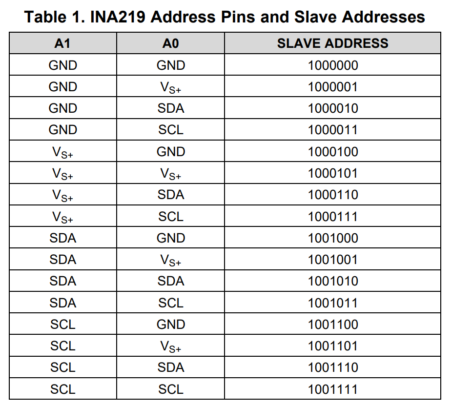
In the datasheet it is defined that we can use this sensor with 16 different addresses. The connection pads are given on the PCB which can be soldered together using those addresses. Usually only 4 addresses are used but here is the full table you can see.
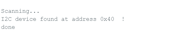
INA219_I2C_ADDRESS1  0x40   A0 = 0  A1 = 0
INA219_I2C_ADDRESS2  0x41   A0 = 1  A1 = 0
INA219_I2C_ADDRESS3  0x44   A0 = 0  A1 = 1
INA219_I2C_ADDRESS4  0x45   A0 = 1  A1 = 1
To configure this INA219 Power sensor we have to define the proper working mode, Range, Gain configurations, voltage (BUS) and current(Shunt) resolution. So here in the code the settings can be edited as per configurations mentioned below in the different tables.
ina.configure(INA219_RANGE_32V, INA219_GAIN_320MV, INA219_BUS_RES_12BIT, INA219_SHUNT_RES_12BIT_1S);
Configuration Settings:
Modes:
INA219_MODE_POWER_DOWN: Power-Down, Quiescent mode
INA219_MODE_SHUNT_TRIG: Shunt Voltage, Triggered on event
INA219_MODE_BUS_TRIG: Bus Voltage, Triggered on event
INA219_MODE_SHUNT_BUS_TRIG: Shunt and Bus, Triggered on event
INA219_MODE_ADC_OFF: ADC Off, stop all conversion
INA219_MODE_SHUNT_CONT: Shunt Voltage, Continuous
INA219_MODE_BUS_CONT: Bus Voltage, Continuous
INA219_MODE_SHUNT_BUS_CONT: Shunt and Bus, Continuous


Range:
INA219_RANGE_16V: 16V
INA219_RANGE_32V: 32V


Gain:
INA219_GAIN_40MV: +/- 40mV
INA219_GAIN_80MV: +/- 80mV
INA219_GAIN_160MV: +/- 160mV
INA219_GAIN_320MV: +/- 320mV
Bus Resolution:
INA219_BUS_RES_9BIT: 9-bit
INA219_BUS_RES_10BIT: 10-bit
INA219_BUS_RES_11BIT: 11-bit
INA219_BUS_RES_12BIT: 12-bit


Shunt resolution:
INA219_SHUNT_RES_9BIT_1S: 9-bit / 1 sample
INA219_SHUNT_RES_10BIT_1S: 10-bit / 1 sample
INA219_SHUNT_RES_11BIT_1S: 11-bit / 1 sample
INA219_SHUNT_RES_12BIT_1S: 12-bit / 1 sample
INA219_SHUNT_RES_12BIT_2S: 12-bit / 2 samples
INA219_SHUNT_RES_12BIT_4S: 12-bit / 4 samples
INA219_SHUNT_RES_12BIT_8S: 12-bit / 8 samples
INA219_SHUNT_RES_12BIT_16S: 12-bit / 16 samples
INA219_SHUNT_RES_12BIT_32S: 12-bit / 32 samples
INA219_SHUNT_RES_12BIT_64S: 12-bit / 64 samples
INA219_SHUNT_RES_12BIT_128S: 12-bit / 128 samples
Components Required:
- INA219 Current sensor
- 12C OLED display
- ARDUINO Nano/UNO
- Jumper wires
- Battery power supply
- Custom PCB from PCBWAY
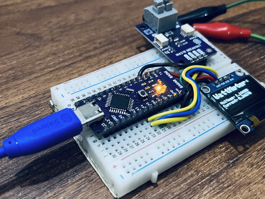
Circuit diagram:
The circuit is quite simple, only 5v is required to power on the sensor and microcontroller. The sensor and OLED both are connected to the I2C port of Arduino Nano. Both have different default addresses so no need to change the address. You can pair almost a maximum of 127 different devices to the I2C port. Follow the schematic...
Read more »
 Jasper Sikken
 Sagar 001

 CentyLab