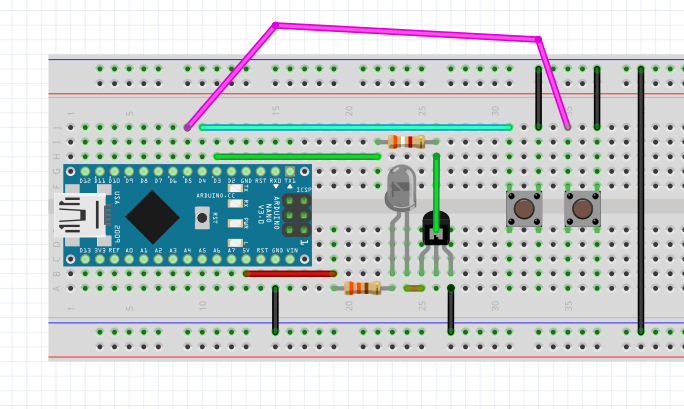
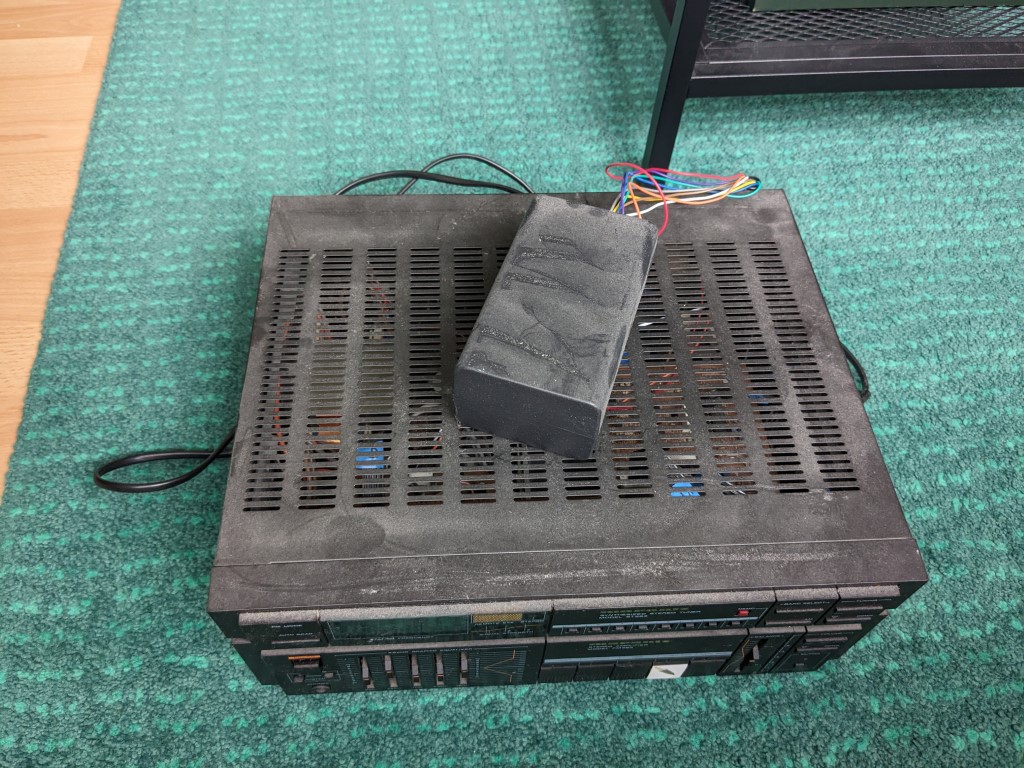
• Final Design

    schlion12/13/2023 at 23:15 0 comments

    What was still open:

    • keep track of the on/standby state in either esphome or Home Assistant
    • solder everything up
    • make a new RCA/chinch cable

    Keeping track of the state is actually fairly simple (if you know where to look). Usually you would need some kind of sensor to know the state. People often use smart plugs with power metering to guess states of e.g. their washing machine. But you can also use the optimistic option:

    switch:
      - platform: template
        name: "Receiver"
        id: receiver_on_off
        optimistic: true
        #is actually the switch to AUX/TV command, but also turns the receiver on
        #RC5 Device/Adress 0 (0x00), Command 63 (0x3F)

    See the final version of my configuration file here (music-control_v2.yaml), I also started using a secrets.yaml file. The optimistic: true does exactly what I want. It assumes the state is as I set it (although it is not very well documented and took me quite some time to find it). I also made the vol+ and vol- into push buttons.

    button:
    #### VolUp/VolDown
      - platform: template
        name: "Volume Up"
        #RC5 Device/Adress 16 (0x10), Command 16 (0x10)
        on_press:
          remote_transmitter.transmit_raw:
            code: [+888, -888, +888, -888, +888, -888, +1776, -888, +888, -888, +888, -888, +888, -888, +888, -1776, +1776, -888, +888, -888, +888, -888, +888]
      - platform: template
        name: "Volume Down"
        #RC5 Device/Adress 16 (0x10), Command 17 (0x11)
        on_press:
          remote_transmitter.transmit_raw:
            code: [+889, -889, +889, -889, +889, -889, +1778, -889, +889, -889, +889, -889, +889, -889, +889, -1778, +1778, -889, +889, -889, +889, -1778, +889]
    ###------------------------------------------

     This is what it looks like in homeassitant:

    So we got the software working and nice ✅


    Hardware time!

    I soldered everything up on some strip board and cleaned off the flux residue with my newly acquired brush.

    My cleaning setup

    With the chinch/RCA connector, I also ordered a USB-C breakout board (the future is now!) And this is how everything looks all soldered up:

    I used hot glue to support the wires, so that they might last a bit longer. I might print a case in the future, but the project still lives in a project box (and will probably live there forever). So hardware and cable are also finished ✅

    Final remarks

    I have been running this setup for about two months now and haven't had any problem. Once or twice the switch in homeassistant got out of sync, but since it isn't a toggle, I can just switch it on and off, and it will be correct again.  I also made the esp turn off the switch (an initialize the state on startup)

    esphome:
      name: musik-control
      on_boot:
        priority: -100
        then:
         switch.turn_off: receiver_on_off

    Because sometimes esp8266 gets buggy and reboots. This way the state is well-defined.

    All in all, I am very happy how it turned out :) thanks for coming along

  • Prettyfication and convenience

    schlion10/24/2023 at 20:05 0 comments

    I've been testing the whole setup on a breadboard for a few days now and everything works as intended.

    To do:

    • keep track of the on/standby state in either esphome or Home Assistant
    • solder everything up
    • make a new RCA/chinch cable

  • Automation with ESP-01 and esphome

    schlion10/20/2023 at 18:42 0 comments

    To make use of all the things I've learned, I want to integrate my receiver control into Home Assistant. I already have a lot of ESP01 modules running esphome for measuring temperature and humidity. esphome is extremely convenient, especially if you want to integrate it into Home Assistant.

    It's is also capable of generating RC5 codes. So I tried that first: hook up and LED via Transistor. Increasing the volume worked like a charm.

      - remote_transmitter.transmit_rc5:
          address: 0x10
          command: 0x10

    The only problem I have now, is that all libraries for sending RC5 codes modulate them with the IR carrier frequency. Which makes a lot of sense. But my signal does not need to be modulated, because it goes in via wire. Luckily, there is a function to transmit "raw" signals (it's just the timing on and off in ns). The default carrier frequency is even 0Hz. Very nice. Using IrScrutinizer I generated the four raw codes for vol+, vol-, standby, and on/AUX, put them in my esphome YAML file:

    esphome:
      name: music-control
    
    esp8266:
      board: esp01_1m
    
    # Enable logging
    logger:
    
    # Enable Home Assistant API
    api:
      id: musik_anlage
      encryption:
        key: "xxxxxxxxxxxxxxxxxxxxxxxxxxxxxxxxxxxxx"
    
    ota:
      password: "xxxxxxxxxxxxxxxx"
    
    wifi:
      ssid: "WIFI-so-fly"
      password: "wouldntyouliketoknow"
    
      # Enable fallback hotspot (captive portal) in case wifi connection fails
      ap:
        ssid: "music-control Fallback Hotspot"
        password: "nope"
    
    captive_portal:
        
    remote_transmitter:
      pin: GPIO3
      carrier_duty_percent: 100%
    
    # Individual switches
    switch:
      - platform: template
        name: "Musikanlage lauter"
        #RC5 Device/Address 16 (0x10), Command 16 (0x10)
        turn_on_action:
          remote_transmitter.transmit_raw:
            code: [+888, -888, +888, -888, +888, -888, +1776, -888, +888, -888, +888, -888, +888, -888, +888, -1776, +1776, -888, +888, -888, +888, -888, +888]
      - platform: template
        name: "Musikanlage leiser"
        #RC5 Device/Address 16 (0x10), Command 17 (0x10)
        turn_on_action:
          remote_transmitter.transmit_raw:
            code: [+889, -889, +889, -889, +889, -889, +1778, -889, +889, -889, +889, -889, +889, -889, +889, -1778, +1778, -889, +889, -889, +889, -1778, +889]
    
      - platform: template
        name: "Musikanlage an"
        #actually the command for changing the source to AUX/TV
        #RC5 Device/Address 0 (0x00), Command 63 (0x3F)
        turn_on_action:
          remote_transmitter.transmit_raw:
            code: [+889, -889, +889, -889, +1778, -889, +889, -889, +889, -889, +889, -889, +889, -1778, +889, -889, +889, -889, +889, -889, +889, -889, +889, -889, +889]
      - platform: template
        name: "Musikanlage standby"
        #actually the command for the tuner to go to standby
        #RC5 Device/Address 17 (0x11), Command 12 (0x0C)
        turn_on_action:
          remote_transmitter.transmit_raw:
            code: [+889, -889, +889, -889, +889, -889, +1778, -889, +889, -889, +889, -1778, +1778, -889, +889, -1778, +889, -889, +1778, -889, +889]
    

    I connected the pin via a 10k Resistor, and it works! Now I can control everything via HA:

    ESP01 hardwired to the receiver

    All that's left to do, is make a nice board, a case, nice wiring and possibly add some more logic, to keep track of the receiver state and possibly turn it off, when nobody's home.

    • Send commands with ESP01 (esphome) via IR LED (triggered in Home assistant) ✅
    • Send commands with ESP01 (esphome) via wire (triggered in Home assistant) ✅

  • Going IR-less

    schlion10/20/2023 at 17:58 0 comments

    I can now:

    • Send IR commands to the receiver
    • send it to standby via IR
    • wake it back up via IR
    • the power socket on the back also turns off in standby

    I had noticed RCA/chinch ports labeled SYSTEM CONTROL RC-5 on the back.

    Apparently the receiver could and would send the RC-5 messages it received vie IR to other devices also I read about the possibility of connecting an additional IR receiver.

    To check it out, I hooked up my "Oscilloscope" (DSO 150 shell). Once I figured out the triggers, I saw this, when sending IR commands in from the front:

    Excellent, a 5V signal. My cheap logic analyzer can work with 5V. So I connected that next, called up pulse view and found the following:

    Very nice, it's the demodulated packet that we sent in from the front. Interestingly, I could only see this on the top port. And for every address + command, I put in, I got a corresponding packet on the analyzer, even if the command didn't actually do anything. But that makes sense.

    Only one thing was weird. I could see the commands, but even the ones that should be working, didn't work anymore. What's happening? I got very confused and checked my code if I had changed anything. After some time, I had the idea to bridge/connect both RC-5 Ports. It turns out, the bottom one is input and the top one output. And if the receiver notices something listening on the RC-5 output, it won't use those command anymore, but rather will wait for them to come back via the bottom port. At least that's my guess.

    This of course means it might be possibly to forgo IR altogether and send the codes directly via wire. Exciting! And much cleaner, than having some IR LED in front of my newish shiny receiver. To test this, I hard-coded one command on an Arduino with half intervals of 889ns, and it worked 🎉

    (see manchester_easy.ino in project files)

    A wired-up Arduino sending a hard-coded transmission

    It's possible to send commands by wire ✅

  • Have you tried turning it off and on agian

    schlion10/20/2023 at 17:26 0 comments

    Or: getting the correct codes

    I can send codes to the device, and they are recognized there ✅

    Next, I need to find out what code I need to send to make the receiver go to standby. And to wake it up again. A nice bonus might be volume control.

    I already know, sending command 16 (0x10) to address/device 16 (0x10) turns the volume up by two. Interestingly, the command for standby 12 (0x0C) sent to device 16 does exactly nothing. So I ran through all the commands on device 16 and got the following:

    Command (DEC)
    Command (HEX)
    Function
    00x00Surround off
    10x01Dolby Pro logic
    20x023 Stereo
    130x0DMUTE (only when not in AUX mode)
    160x10Volume Up
    170x11Volume Down
    380x26Sleep (10-min sleep timer)
    460x2ENORMAL/WIDE (?center mode?)
    880x58TEST--C/TEST--FR
    1020x66CENT+
    1020x76CENT-

    All the other ones did nothing, although it is entirely possible, that combinations might so something. E.g. there must be a way to manipulate the sleep timer setting. But I'm not very interested in that, so I called it a day.

    Cool, so I can do some wild stuff, but really I would like to send this whole thing to standby and wake it up again. Somewhere on the interwebs I read, that the receiver used to interpret the IR signal and relay it to other devices. So I tried different device numbers and lo and behold, using the standby code 12 (0x0C) with basically any other device/address worked. Nice! But I'm still not sure why this works. I would assume, if I'm sending the standby signal to the TV (device 0, 0x00), it would turn the TV off, but not my receiver?

    Anyway, later I realized, that the tuner in the receiver is addressed by 17 (0x11) and it seemed right to turn the device off with (17=0x11, 12=0x0C).

    Receiver goes to standby ✅

    But how do I get it to turn back on? None of the commands on device 16 did anything to that effect. And sending the standby code again did not toggle standby mode on this device. However, pressing the physical source buttons on the device did end standby mode. Only I had no idea how to achieve the same thing via IR.

    Side note: I checked, if the power outlet on the back would turn off in standby mode. And lucky me, it did :) Otherwise I could have stopped my project now. Without any possibility of controlling the Bluetooth dongle, I would have to resort to the smart switched outlet again, no need for fancy IR communication.

    After a lot more digging and reading the documentation properly, I noticed command 63 (0x3F), which does some kind of source select. So I sent it to device 16 and nothing happened. Then I tried sending it to different devices and that actually worked:

    Device/Address (DEC)
    Device/Address (HEX)Source
    00x00TV/AUX
    40x00CD/V-CD/CD-i
    50x05VCR 1
    60x06VCR 2
    170x11TUNER
    180x12TAPE/DCC
    200x14CD/V-CD/CD-i (again)
    230x17TAPE

    Now I can select the source ✅ and also get the receiver out of standby ✅


    Finding the correct address/device and command was extremely tedious. At some point, I decided to make my life easier and install two buttons, one for repeating the transmission and one for incrementing either the address or the command. But any time you use buttons, you'll have to debounce :/ See my SimpleSenderTest.ino file in the project files.

    Also, here's the schematic and breadboard:

    Schematic: transmitter with buttons
    Breadboard: transmitter with buttons

  • no remote, no problem

    schlion10/18/2023 at 15:53 0 comments

    First I wanted to find out, If the power socket on the back would turn off, if the device was in standby. Unfortunately, I do not have a remote and no way to reach standby without it, just proper off and on.

    So I threw together a circuit and tried using the IRremote Arduino library. But I had no luck. I found out that my device would probably use RC5 IR encoding (possibly even extended RC5 (RC5x)). I did find https://github.com/probonopd/irdb which has many IR commands for loads of devices. Furthermore, I tried encoding some data I found it with IRSrutinizer and sending it via

    IrSender.sendRaw(.....)

    None of this worked. So I checked my setup: Was there even light coming out of the IR LED? Yes, using the old phone camera trick, I could see flashes from the LED. 

    Does the LED have the right wavelength and is it bright enough? To test this, I needed a known good. So I got an IR Receiver Module and used the RecieveDump-example from the IRremote library to get the code for power toggle on my other stereo system.

    Protocol=NEC Address=0x78 Command=0xF Raw-Data=0xF00F8778 32 bits LSB first
    
    Send with: IrSender.sendNEC(0x78, 0xF, <numberOfRepeats>);
    
    Raw result in internal ticks (50 us) - with leading gap
    rawData[68]: 
     -65535
     +179,-88
     +12,-10 +12,-10 +12,-10 +13,-32
     +12,-32 +12,-32 +12,-33 +12,-10
     +12,-32 +12,-32 +13,-32 +12,-10
     +12,-10 +12,-11 +12,-10 +12,-32
     +12,-32 +13,-32 +12,-32 +12,-32
     +13,-10 +12,-10 +12,-10 +12,-10
     +12,-11 +12,-10 +12,-10 +12,-10
     +12,-33 +12,-32 +12,-32 +12,-32
     +13
     Sum: 1344
    Raw result in microseconds - with leading gap
    rawData[68]: 
     -3276750
     +8950,-4400
     + 600,- 500 + 600,- 500 + 600,- 500 + 650,-1600
     + 600,-1600 + 600,-1600 + 600,-1650 + 600,- 500
     + 600,-1600 + 600,-1600 + 650,-1600 + 600,- 500
     + 600,- 500 + 600,- 550 + 600,- 500 + 600,-1600
     + 600,-1600 + 650,-1600 + 600,-1600 + 600,-1600
     + 650,- 500 + 600,- 500 + 600,- 500 + 600,- 500
     + 600,- 550 + 600,- 500 + 600,- 500 + 600,- 500
     + 600,-1650 + 600,-1600 + 600,-1600 + 600,-1600
     + 650
    Sum: 67200
    
    Result as internal 8bit ticks (50 us) array - compensated with MARK_EXCESS_MICROS=20
    uint8_t rawTicks[67] = {179,88, 12,10, 12,10, 12,10, 13,32, 12,32, 12,32, 12,33, 12,10, 12,32, 12,32, 13,32, 12,10, 12,10, 12,11, 12,10, 12,32, 12,32, 13,32, 12,32, 12,32, 13,10, 12,10, 12,10, 12,10, 12,11, 12,10, 12,10, 12,10, 12,33, 12,32, 12,32, 12,32, 13};  // Protocol=NEC Address=0x78 Command=0xF Raw-Data=0xF00F8778 32 bits LSB first
    
    Result as microseconds array - compensated with MARK_EXCESS_MICROS=20
    uint16_t rawData[67] = {8930,4420, 580,520, 580,520, 580,520, 630,1620, 580,1620, 580,1620, 580,1670, 580,520, 580,1620, 580,1620, 630,1620, 580,520, 580,520, 580,570, 580,520, 580,1620, 580,1620, 630,1620, 580,1620, 580,1620, 630,520, 580,520, 580,520, 580,520, 580,570, 580,520, 580,520, 580,520, 580,1670, 580,1620, 580,1620, 580,1620, 630};  // Protocol=NEC Address=0x78 Command=0xF Raw-Data=0xF00F8778 32 bits LSB first
    
    uint16_t address = 0x78;
    uint16_t command = 0xF;
    uint32_t rawData = 0xF00F8778;
    
    Pronto Hex as string
    char prontoData[] = "0000 006D 0022 0000 0159 00A8 0018 0012 0018 0012 0018 0012 001A 003D 0018 003D 0018 003D 0018 003F 0018 0012 0018 003D 0018 003D 001A 003D 0018 0012 0018 0012 0018 0014 0018 0012 0018 003D 0018 003D 001A 003D 0018 003D 0018 003D 001A 0012 0018 0012 0018 0012 0018 0012 0018 0014 0018 0012 0018 0012 0018 0012 0018 003F 0018 003D 0018 003D 0018 003D 001A 06C3 ";


    Which is extremely helpful, as it even gives the transmit-command

    IrSender.sendNEC(0x78, 0xF, 0);

     So I got the simpleSender example, plugged the command and voilà: It worked!

    We now know that the transmitterworks ✅

    So I fiddled around with the IRremote library and found the command for sending RC5

    IrSender.sendNEC(aAddress, aCommand, aNumberOfRepeats, aEnableAutomaticToggle)

     The biggest struggle for me, was to understand, that the device number listed in different manuals (Wikipedia, irdb) is the same as the address...

    Read more »

  • Obituary and new stereo amplifier

    schlion10/18/2023 at 15:19 0 comments

    My old Marantz RX 263 ampilfier became flaky and died :(

    So I got a new one on kleinanzeigen (basically German Craigslist) for 20 €.

    Before we ha an extension cord with TP-Link Kasa smart plug. It would turn on the amplifier and a Bluetooth dongle. Since the amplifier did not have any persistent memory, there were two timed relays, connected to the AUX and the VOL+ button, to set the correct volume and input. I'm actually quite proud of the solution, and it served me well for 8 years. What might have killed the amplifier, was me stealing power from the +16V rail, for the relays. Or turning it on and off at the outlet. Or it just gave up. Who knows.

    All of this hassle for being able to have music in the kitchen and turn it on and off via home assistant.

    The new amplifier, a Philips FR732 has persistent memory. So now I could just plug it into the extension cord and call it a day. But I don't want to kill another amplifier by forcefully turning it on and off. Also there is a power socket on the back which can probably turn a device (e.g. my Bluetooth dongle) on and off.