 gokux
gokux The project is not that complicated due to the small number of components thanks to the clever design of INA219 ic. Here is the schematic of this circuit, the communication between ina219 and OLED to Xiao is done through I2c, this circuit is powered by connected USB power from Xiao, and two wire connecting terminals are used for input and output

for this project, I sourced all the parts for the INA219 current sensor module, I desolder all the components from that module. and solder all the components to the new PCB, in the end, solder both the OLED and wire connector
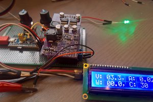
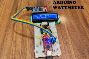
 I just connected a 12v DC to the input power terminal, on the output terminal, I added a 68-ohm resistor as a load. the whole circuit is powered by the USB power input from Xiao. The OLED screen will show you the voltage, current, and power in milliwatts. it is recommended to use this in below 26 volts and 3 amp. applying a higher current or voltage from the rated value will damage the circuit
If you need the Gerber file and Schematics of this project click this link
 Lithium ION
 mircemk
 Jakob Wulfkind