 gokux
gokux
#include <SPI.h>
#include <Wire.h>
#include <Adafruit_GFX.h>
#include <Adafruit_SSD1306.h>
#define SCREEN_WIDTH 128 // OLED display width, in pixels
#define SCREEN_HEIGHT 64 // OLED display height, in pixels
#define OLED_RESET     -1 // Reset pin # (or -1 if sharing Arduino reset pin)
#define SCREEN_ADDRESS 0x3D ///< See datasheet for Address; 0x3D for 128x64, 0x3C for 128x32
Adafruit_SSD1306 display(SCREEN_WIDTH, SCREEN_HEIGHT, &Wire, OLED_RESET);
const int numThermistors = 6;
const int analogPins[numThermistors] = {A0, A1, A2, A3, A6, A7};
const float pullUpResistance = 4700.0; // 10k ohm
const float referenceResistance = 100000.0; // 100k ohm at 25°C
const float betaCoefficient = 3950.0; // Beta coefficient for the NTC thermistor
const float nominalTemperature = 30.5; // Nominal temperature for the NTC thermistor in °C
void setup() {
Serial.begin(9600);
// SSD1306_SWITCHCAPVCC = generate display voltage from 3.3V internally
if(!display.begin(SSD1306_SWITCHCAPVCC, SCREEN_ADDRESS)) {
Serial.println(F("SSD1306 allocation failed"));
for(;;); // Don't proceed, loop forever
}
display.clearDisplay();
display.setTextColor(WHITE);
}
void loop() {
display.clearDisplay();
for (int i = 0; i < numThermistors; i++) {
float rawReading = analogRead(analogPins[i]);
float resistance = pullUpResistance / (1023.0 / rawReading - 1.0);
float temperature = 1.0 / ((1.0 / (nominalTemperature + 273.15)) + (1.0 / betaCoefficient) * log(resistance / referenceResistance)) - 273.15;
display.setTextSize(1);
display.setCursor(22,i * 10);
display.print("T ");
display.print(i);
display.print(": ");
display.print(temperature);
display.println(".C");
}
display.display();
delay(300); // Delay for 1 second before reading again
}
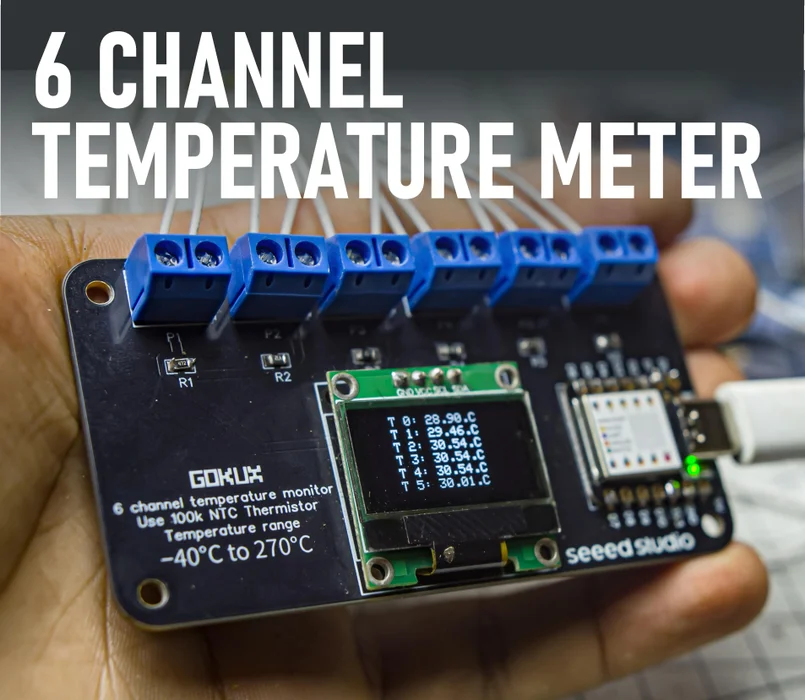
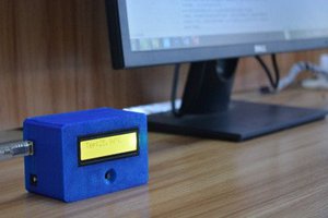
I always wanted a thermal camera for measuring temperature from different locations at the same time. But the thermal camera is expensive for me, so I decided to make a cheap DIY multi-channel temperature meter for scientific use, which has a −40°C to 270°C wide temperature range
In this project, we are making a temperature meter project that has 6 NTC thermistors and an OLED screen that will show the reading from the different temperature sensors simultaneously. All of this is controlled by Seeed Studio XIAO SAMD21
Parts
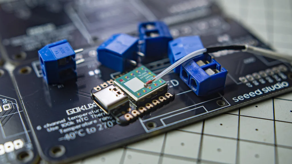
6* 4.7k resistors 0805 SMD (resistor kit 0805)
6* KF301 2 Pin 5.08mm Pitch Plug-in Screw Terminal Block Connector
How NTC thermistor works

An NTC thermistor, short for Negative Temperature Coefficient thermistor, is a type of resistor that exhibits a decrease in resistance as temperature increases. This behavior is due to the semiconductor material used in its construction, which allows more electrons to flow when heated. NTC thermistors are commonly employed as temperature sensors due to their high sensitivity and wide operating range. To measure temperature, an electrical current is passed through the thermistor, and the resulting voltage drop is measured. This voltage drop is proportional to the thermistor's resistance, which in turn is inversely proportional to the temperature. For this project, we are using a 100K NTC thermistor which is cheap and widely available. It is used in 3D printers, so it comes with 1-meter wire.
Schematic
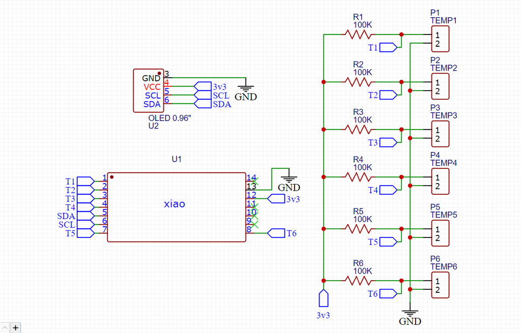
To measure temperature with an NTC thermistor, we can use a simple voltage divider circuit ,with the thermistor as one of the resistors. The output voltage of the bridge is proportional to the resistance of the thermistor, which in turn is inversely proportional to the temperature. We can use a microcontroller to measure these voltages and convert it to temperature. and used a small OLED screen for interfacing that data
PCB
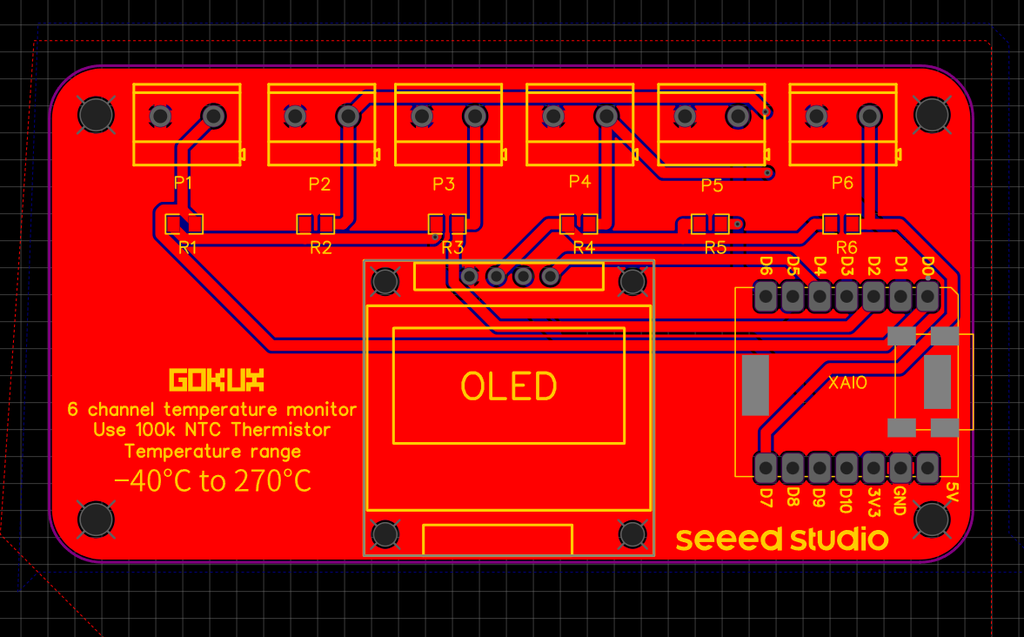
I designed this pcb according to the schematics given above using easyeda and exported it to Gerber file for fabrication
PCB fabrication
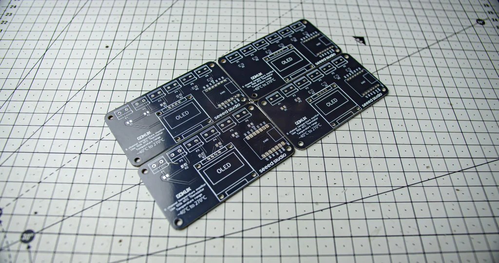
I used Seeed Studio Fusion service for ordering...
Read more »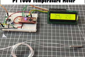
 Lithium ION
 Darren Blaxcell, aka Pork
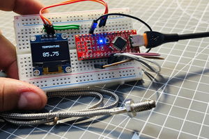
 muzi
muzi