 Mrinnovative
Supplies

this is the complete BOM of the motor control board.
1. 22pF C3,C4 C1206 2 1206CG220J500NT
2. 1uF C6 C1206 1 12065C105JAT2A
3. 100nF C7 CAP-TH_L13.0-W6.0-P10.00-D0.6 1 MPX104K31C3KN15600
4. 10uF C16 C1206 1 CC1206ZKY5V7BB106
5. DB128V-5.08-5P-GN-S CN1 CONN-TH_5P-P5.08_DIBO_DB128V-5.08-5P-GN-S 1 DB128V-5.08-5P-GN-S
6. MB10S_C2488 D1 MBS_L4.7-W3.8-P2.40-LS7.0-TL 1 MB10S
7. SM712-02HTG_C2827658 D6 SOT-23_L2.9-W1.3-P1.90-LS2.4-BR 1 SM712-02HTG
8. ICSP ICSP1,MODE,SLAVE_ID HDR-M-2.54_2X3 3
9. HB9500-9.5-3P MAINS,MOTOR CONN-TH_HB9500-9.5-3P 2 HB9500-9.5-3P
10. SN65HVD3082EDR MAX485 SOIC-8_L5.0-W4.0-P1.27-LS6.0-BL 1 SN65HVD3082EDR
11. FC-3215HRK-620D PWR LED1206-R-RD_RED 1 NCD1206R1
12. BTA41-600BRG Q1 TOP3_L15.3-W4.5-P5.60-L 1 BTA41-600BRG
13. 47k R1,R2,R3,R4 R_AXIAL-0.4 4
14. 10k R5 R_AXIAL-0.4 1
15. 220 R6 R_AXIAL-0.4 1
16. 100 R7 R_AXIAL-0.8 1
17. 360 R8 R_AXIAL-0.5 1
18. 470 R9 R_AXIAL-0.5 1
19. 120Ω R10,R12 R1206 2 ARG06FTC1200
20. 1kΩ R13,R14 R1206 2 RMC12061K5%N
21. 220Ω R15 R1206 1 1206W4F2200T5E
22. 10K R16,R17,R18,R19 R1206 4 RT1206BRD0710KL
23. 3.3kΩ R22,R23 R1206 2 RMC12063.3K1%N
24. XY2500R-C-5.08-3P RS48_RTU CONN-TH_XY2500R-C-5.08-3P 1 XY2500R-C-5.08-3P
25. FC-3215GHK-570A08 SYS13 LED1206-RD 1 NCD1206C1
26. LTV-817-D U1 DIP-4_L6.4-W4.6-P2.54-LS7.6-BL 1 LTV-817-D
27. MOC3021M U2 DIP-6_L7.3-W6.5-P2.54-LS7.6-BL 1 MOC3021M
28. HEAT SINK U3 HEATSINK-TH_L23.5-W16.0-P18.0_XSD2156-067 1 23.5*16*25 2个钉散热片
29. ATMEGA328P-AU U4 TQFP-32_L7.0-W7.0-P0.80-LS9.0-BL 1 ATMEGA328P-AU
30. SMD1812B050TF U5,U6 R1812 2 SMD1812B050TF
31. 47nF U8 CAP-TH_L12.0-W6.0-P10.00-D1.0-FD 1 ECQE6473JF
32. HLK-PM01 U9 PWRM-TH_HLK-PM01 1 HLK-PM01
33. X2 HC-49US_L11.5-W4.5-P4.88 1 XIHCELNANF-16MHZ
Step 1: CIRCUIT DIAGRAM AND PCB

his AC motor speed controller is work on Zero cross detection principle
Zero-cross detection is a technique commonly employed in motor control systems to regulate the speed of motors, particularly in applications where precise control is required. The basic idea is to synchronize the activation of a device, such as a triac, with the zero-crossing points of the AC waveform. This synchronization helps minimize the electrical noise and improves the efficiency of the system.
Here's a detailed explanation of how zero-cross detection is used to control the speed of a motor using the MOC3021 optoisolator and BT41-600 triac:
1. **Components Used:**
- **MOC3021 Optoisolator:** This is a component that combines a phototransistor and a light-emitting diode (LED) in a single package. It provides electrical isolation between the input (control) and output (load) circuits.
- **BT41-600 Triac:** A triac is a semiconductor device that can control AC power. The BT41-600 is a specific type of triac that can handle higher power levels.
2. **Zero-Cross Detection:**
- The MOC3021 optoisolator is used to detect the zero-crossing points of the AC waveform. The AC voltage is applied to the input side of the optoisolator.
- The optoisolator's internal LED is turned on and off in sync with the AC waveform. The phototransistor senses the light emitted by the LED.
- The output of the optoisolator switches state when the AC waveform crosses zero voltage, providing a signal that indicates the zero-crossing points.
3. **Control Signal Generation:**
- The output of the MOC3021 is used to generate a control signal that is fed to the gate of the BT41-600 triac.
- The triac controls the power supplied to the motor. It allows the current to flow in both directions once triggered.
4. **Motor Speed Control:**
- By synchronizing the activation of the triac with the zero-crossing points of the AC waveform, the motor can be controlled more precisely.
- The speed of the motor is adjusted by regulating the duration...
Read more »
 Mark Atherton
 Osman Mazinov
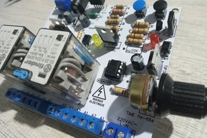
 ElectronicABC