 mircemk
Rife machines are often promoted as devices that emit electromagnetic frequencies to destroy pathogens, including viruses and bacteria. However, these claims lack robust scientific validation. Royal Raymond Rife, the inventor of the Rife machine, claimed that it could treat various diseases by transmitting specific frequencies.
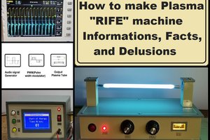
In several of my previous videos , I described the principle of operation of these devices, as well as practical examples of making simple and advanced Rife Machines. This time I will describe how to make a simpler version of the project "DIY Advanced Plasma Rife Machine", but also at the request of several of my followers I will describe the hardware part in more detail with given circuit diagrams.
Namely, in the previously mentioned project, the part with the Microcontroller (the oscillator which is actually the carrier of the signal) is relatively complex to make for most self-builders, this time I decided to make this part in a much simpler way with discrete elements.
First, let's look at the block diagram of the Rife machine, to explain the working principle more easily.
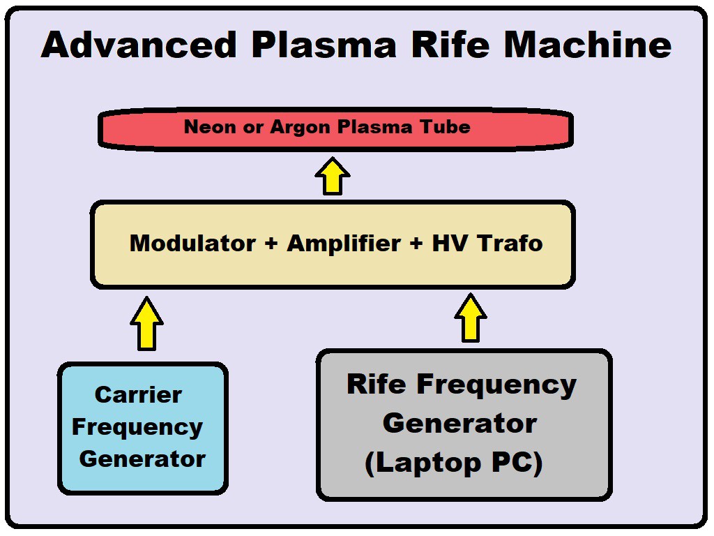
As we can see, the components are:
- Carrier frequency generator
- Generator of Rife Frequencies, in this particular case it is Frex16 software which is free, and is described in more detail in the previous video of this area
- Modulator + HF Amplifier + HV transformer, which serves to insert the Rife frequencies into the carrier frequency and the thus modulated signal is amplified and sent to the transformer whose output produces a high voltage for driving the plasma tube,
- And the Plasma Tube that emits this signal into the environment.
Now we will mostly focus on the Carrier frequency generator because this is actually the difference between the previous device and this one.
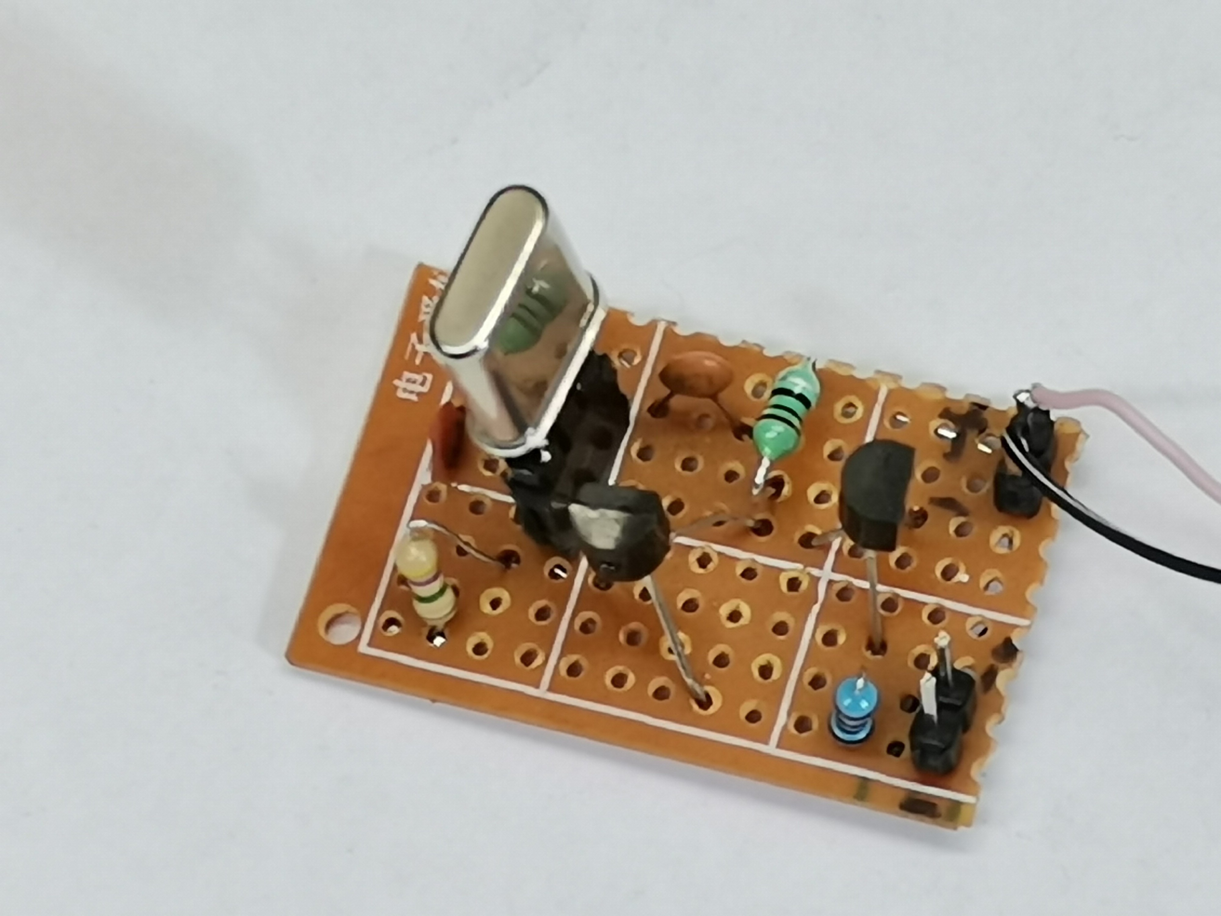
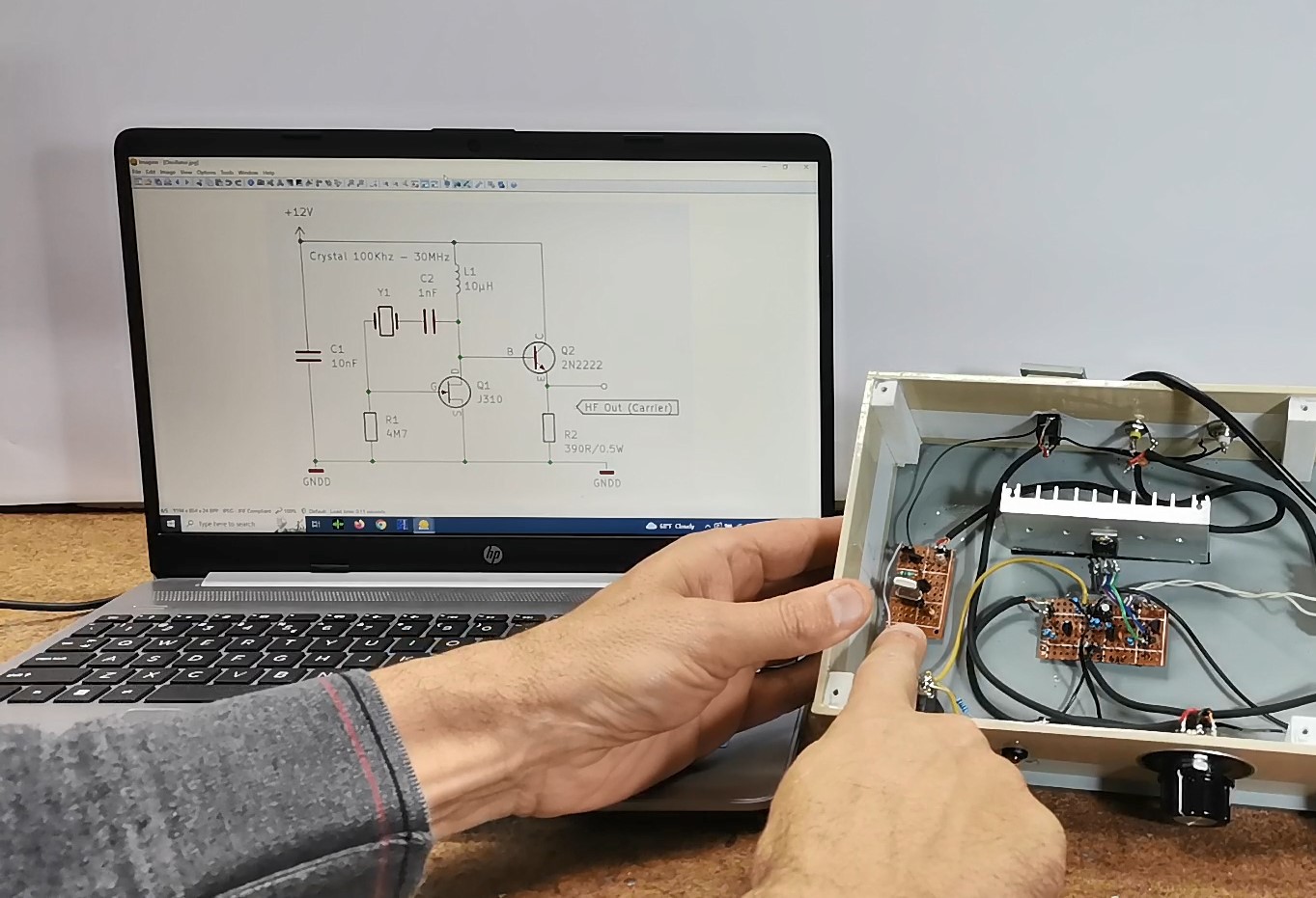
It's this little board, and this is the schematic of the oscillator. Although many Rife machines are sold on the commercial market not exceed 100 kilohertz, the original machine made by Rife has a carrier of around 3 MHz.
If you want to make a PCB for this project, or for any other electronic project, PCBway is a great choice for you. PCBway is one of the most experienced PCB manufacturing company in China in field of PCB prototype and fabrication. They provide completed PCB assembly service with worldwide free shipping , and ISO9001 quality control system. Also, on their site there is an online gerber viewer where you can upload your gerber and drill files to render your board.

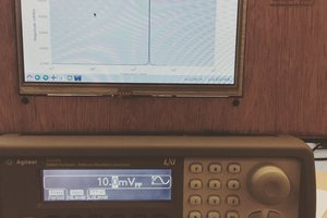
This generator is capable of generating a carrier frequency in the range of 100Khz to 30 MHz depending on the filter used, unlike the previous time where we could change the frequency continuously. I currently have 6MHz, 14.3MHz, and 20MHz crystal oscillators and will test it individually with all three. I placed a special connector on the board so that I can change the crystals quickly and without soldering. Just to mention that any other carrier frequency source can be used in place of this oscillator, such as in the previous project where the SI5351 Retro look VFO oscillator was used, and for which you can also find building instructions on my channel. Now I will demonstrate to you what the shape of the carrier signal looks like on an oscilloscope.
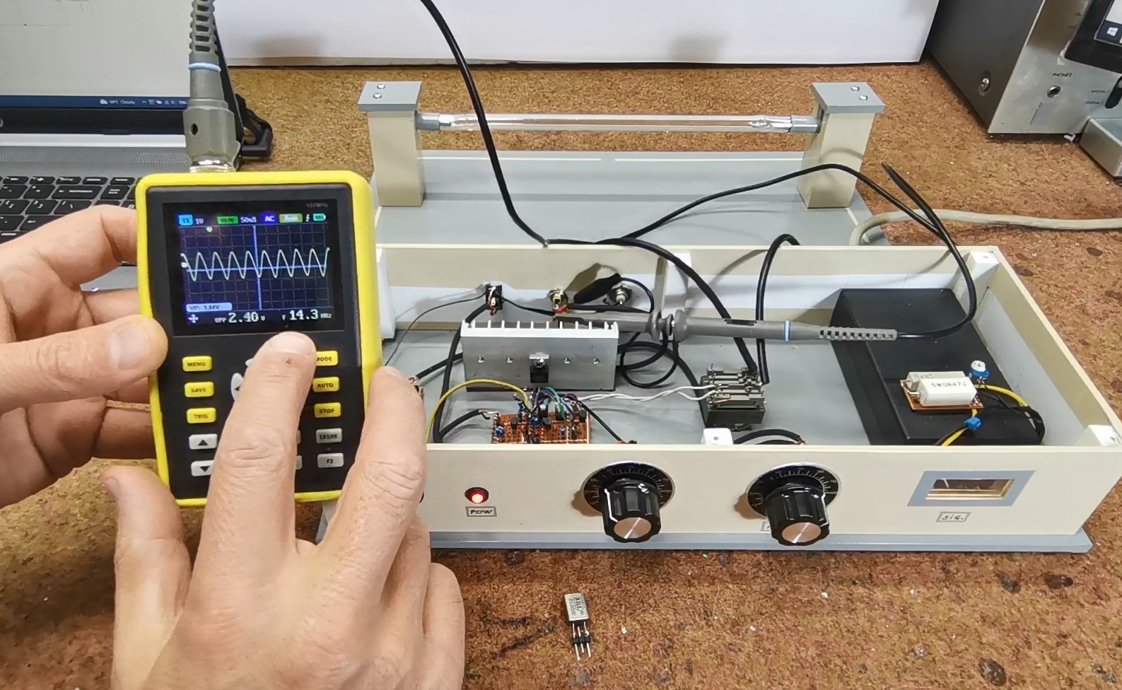
As we see signal is sinusaidal.
So we can place a crystal on the board with any value between 100kHz and 30MHz, and that will change the oscillating frequency. If we want to experiment with more carrier signals, we can install a mechanical switch that will change the crystal, as well as the frequency of the carrier.
Another board represents an AM modulator with an amplifier, so the modulated signal thus obtained is fed to the HV transformer.
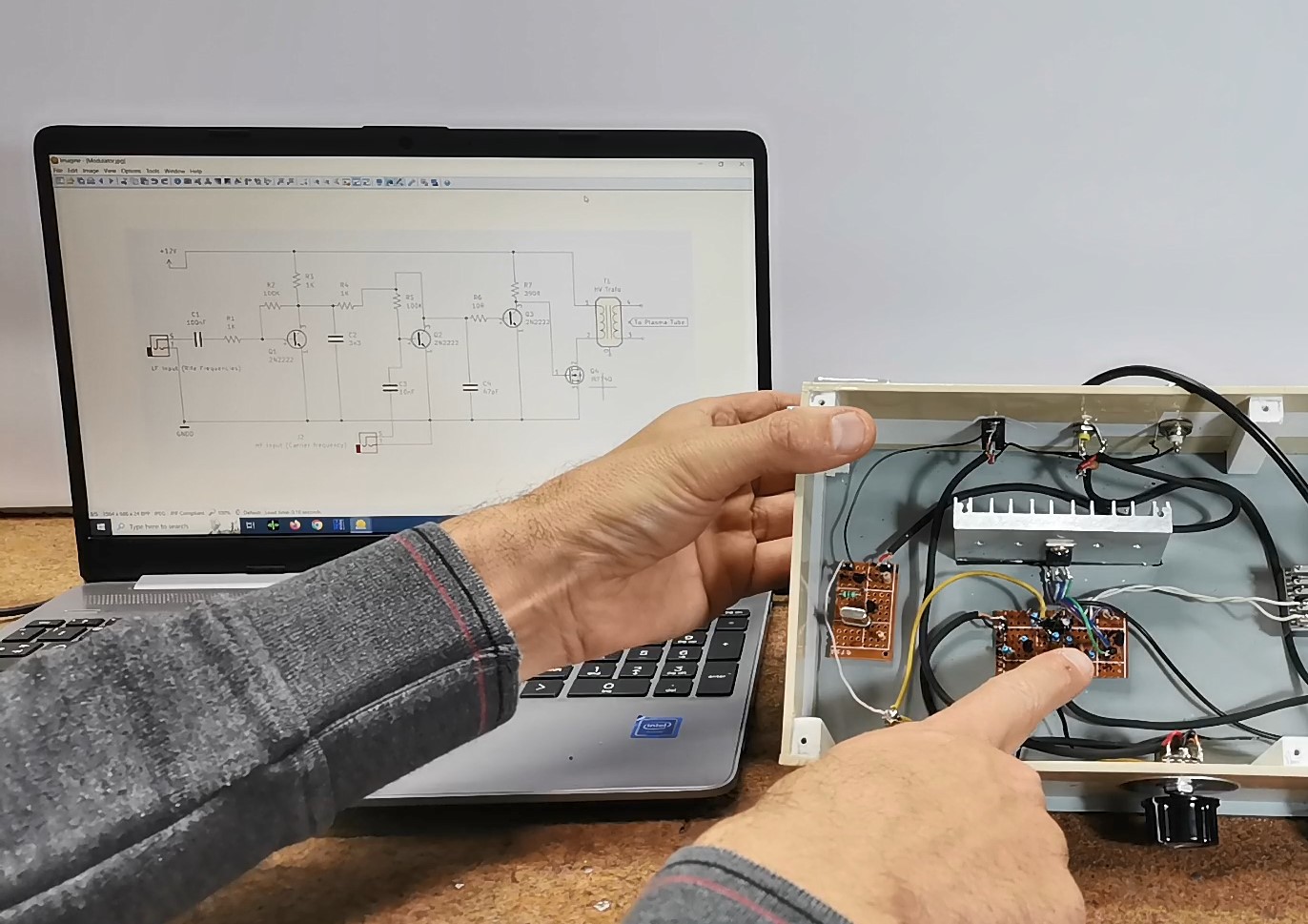
The high-frequency carrier signal is fed to HF+ input, and the low-frequency Rife signal, which is incorporated into the carrier, to the LF input. From the transformer, the HV signal is brought to the plasma tube,...
Read more »

 Dan Kisling