 Alan Penner
Inspired by this CreeRelays project, I wanted to build something that reads the dimming levels of the Zigbee board in the Cree Connected Bulb. After a few attempts using the strategy there, I found a few problems. First, the PWM output from the Cree board is not entirely linear, so the way CreeRelays maps to dimming level doesn't quite work for all the levels. That could be fixed with a lookup table.
The second problem I couldn't solve with just the Arduino: The timing is so sensitive reading the PWM signal from the Cree board that trying to do anything else with the Arduino, especially any operations requiring interrupts, threw off the readings.
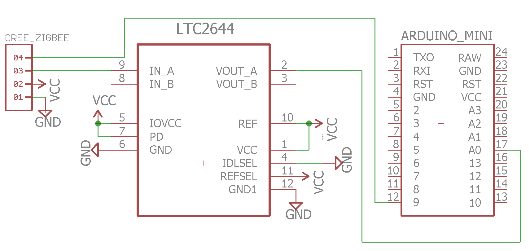
The solution: Use a separate DAC to convert the PWM signal to a fixed voltage, and monitor that on an Arduino analog pin for changes.
Once I had the DAC hooked up, I set the bulb to each of the 100 dim levels, and recorded the data out of the analog pin for about 30 seconds. The analog pin on the Arduino returns a value from 0 to 1023. Each dimming level fluctuated between 2 and 5 different values, with the bulk of it usually being just 2. From the data I collected, I created a count of how many of each value were read for each level. I dropped values that had very few results, and used the resulting data to create the "cutoffs" array in the Arduino sketch. These are the start and end point for each dimming level on the bulb. The raw (grouped) data can be found in data.txt.
When the bulb changes brightness, there's a ramp up or ramp down time, and the intermediate values are output in the PWM signal. Due to this, in the Arduino sketch, I have to wait until the value stabilizes when it is changing before being sure that it's changed to a new dimming level. The number of readings before calling it stable was determined simply through trial and error.
In the attached CreeRead.mp4 video file, you can see output from the Arduino with the proper dimming level when it is changed through a Staples Connect home automation hub.


 Alessandro Sottocornola
 adria.junyent-ferre
 mircemk
 Jerry Isdale
Awesome project!
I have been battling the Cree dimming function too. I tried measuring the PWM in various digital ways, but found it was too unstable. I ended up with a simple RC low pass filter (RC=100ms, so about 1/10 the PWM frequency) into an Arduino analog pin. That cleaned up the signal a lot. It's not perfect, but usable for my purpose (drive the digital brightness of programmable RGB LEDs) and a bit of Arduino code can help with the remaining jitter/ripple.
How stable is the DAC route with the measured steps? 100% stable?