 Eddie
EddieWake Up and Scream
2023
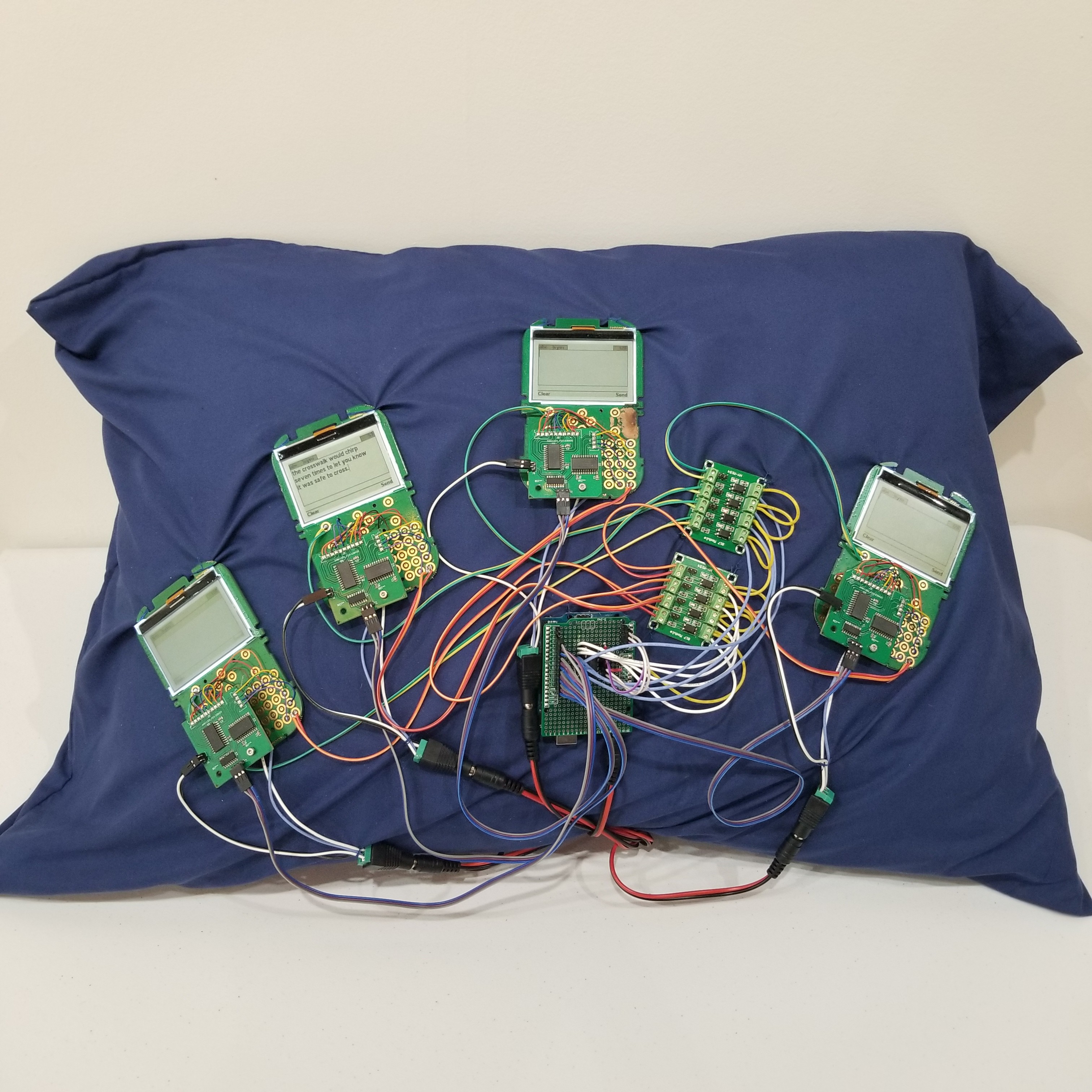
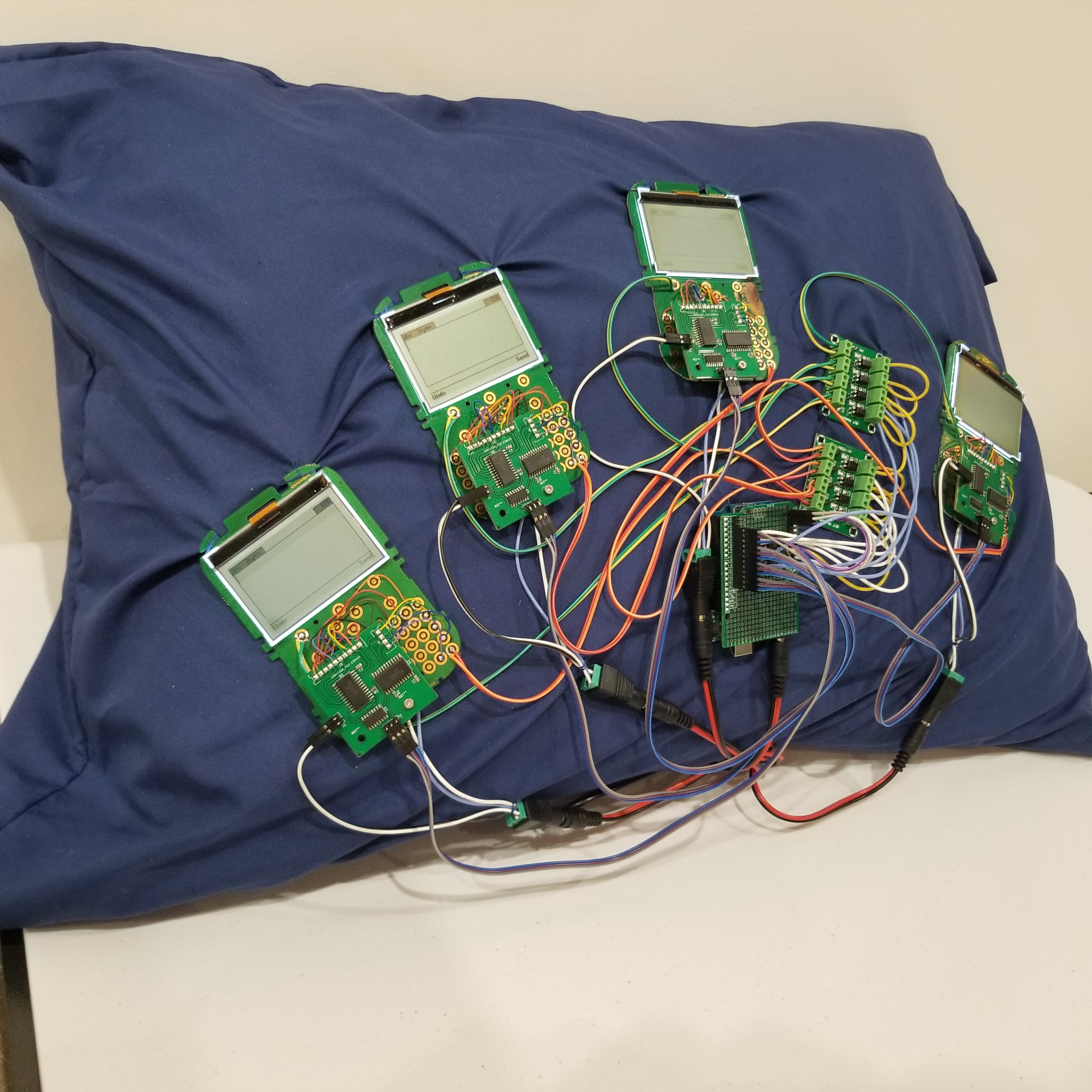
Student Clickers, Wire, Electronics, Fabric
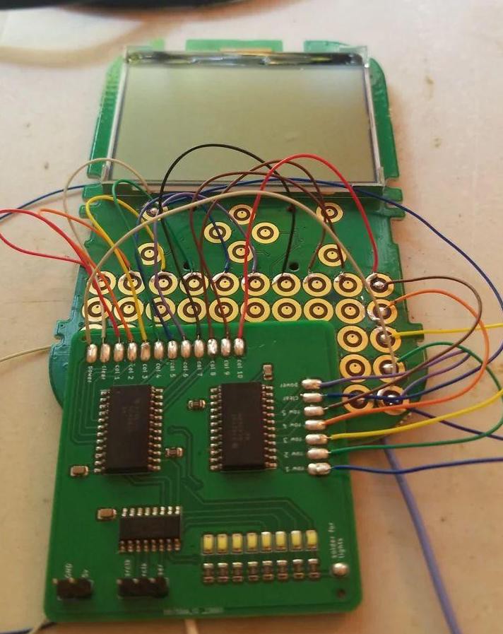
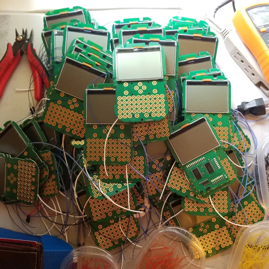
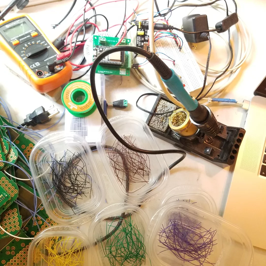
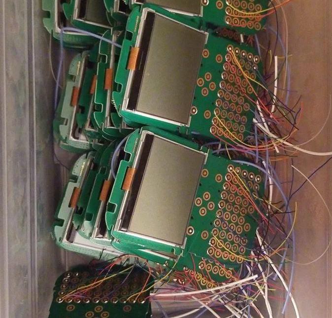
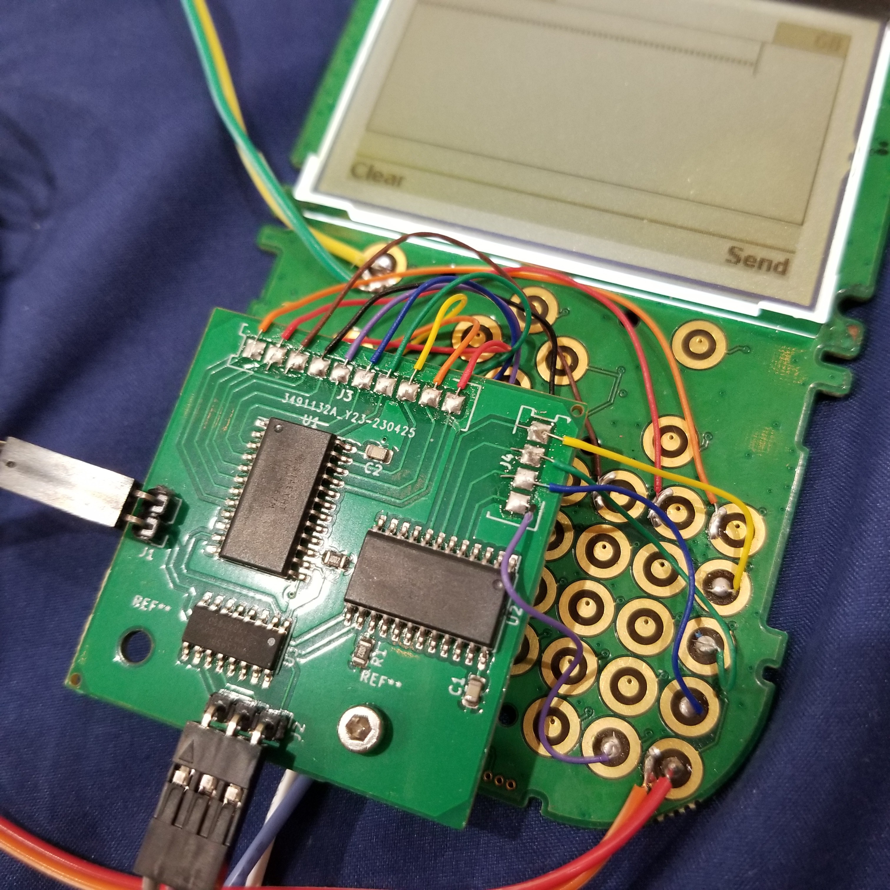
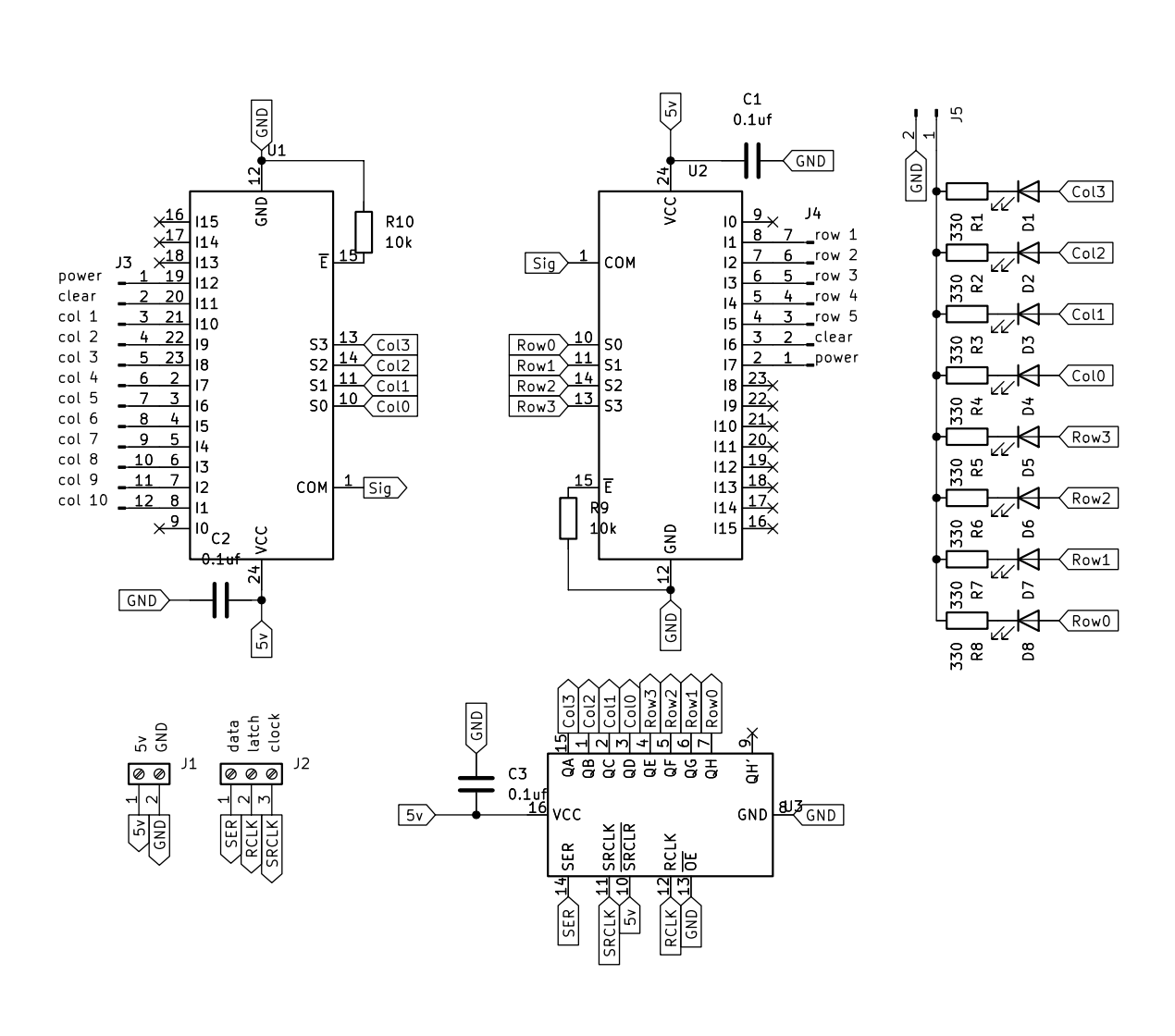
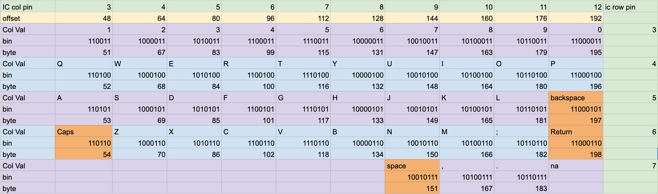
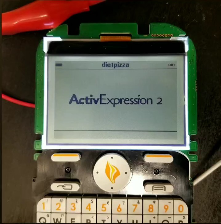
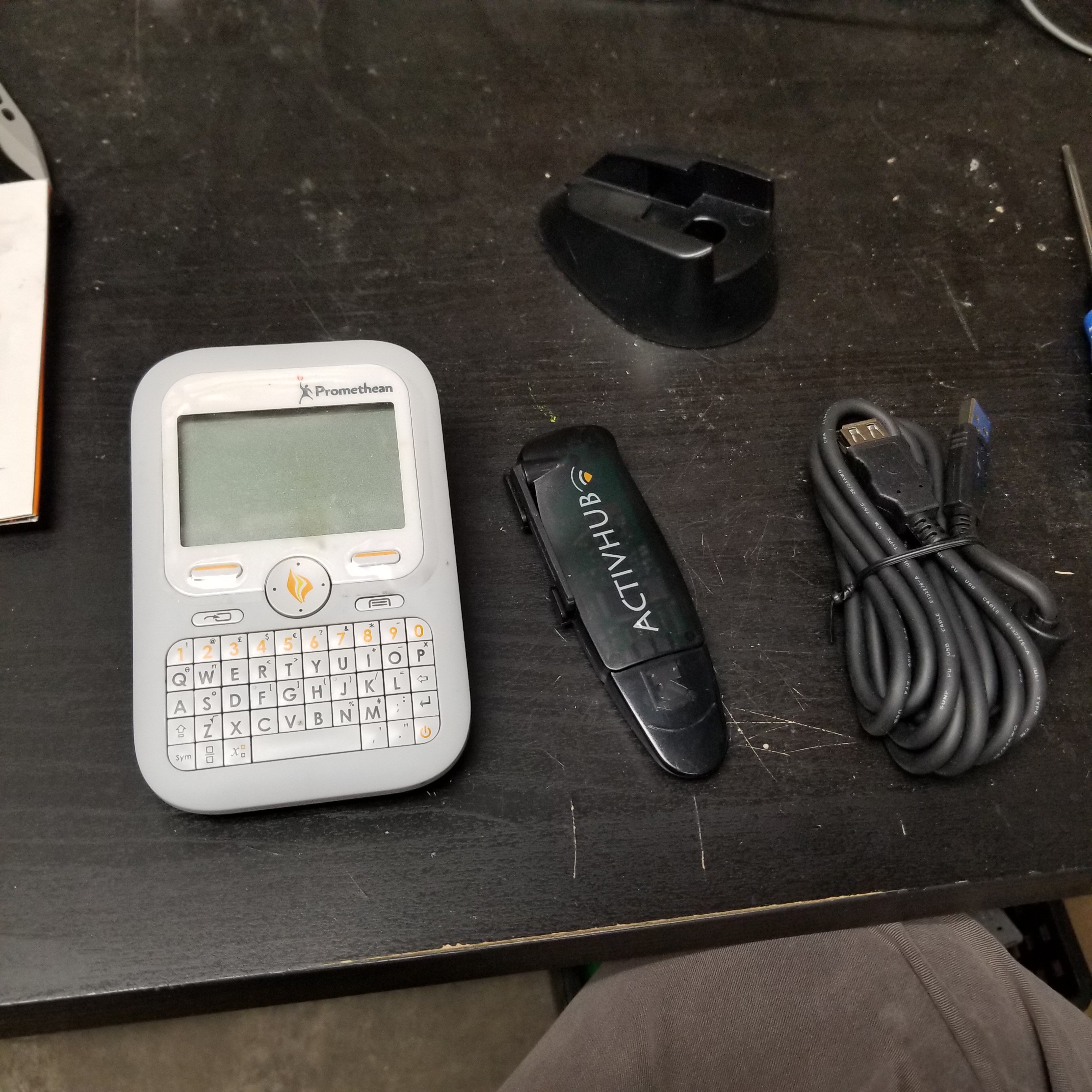
48 hardware-modified student clickers are controlled in groups of 6 by Arduino Nanos.
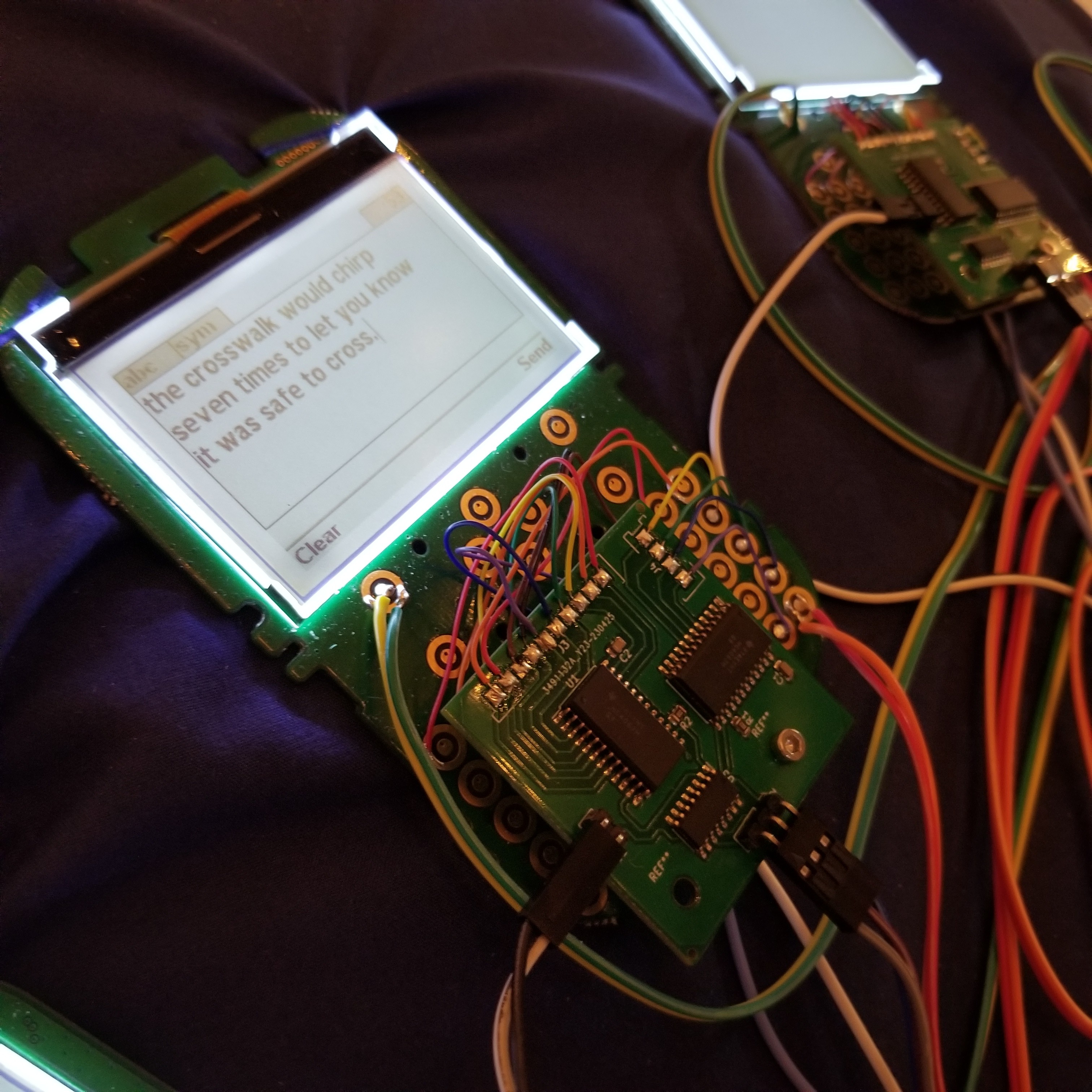
The clickers have been modified to work autonomously without a human operator. They can power on, type, clear the screens, and power off.
Designed as a wearable sculpture two batteries, in pockets, provide power to all the components.
Currently, the piece just types gibberish, akin to my mind in the mornings before coffee. In the future, I would like it be able to tell stories across all the screens. A real time choose your own adventure maybe.
Some background:
Toward the end of my residency at the Fulton County Futures Lab l I was programming a lot of automated routines to collect and process data. The data was then used to generate art! While I was doing all of the coding I got attached to the idea of having the computer program itself to create the art. Not just running an automated routine but digitally typing into an IDE so that viewers could see.
I liked the idea of the computer getting flustered that it was being watched and making mistakes that it would then have to correct. Similarly when I try and code/type in front of others. I explored how to type authentically like a human would, not just type at a constant rate. A performance that would be undertaken entirely by the computer. It is not a true artificial intelligence but more of a mechanical automata.
I ultimately scrapped this idea at the time due to fatigue and illness but kept it close while I was recovering from COVID-19. When I stumbled across this lot of old student clickers the idea came back and I decided to pursue it. I like the idea that these devices are performers. They are actors who know a set of rules. Rules you don’t know but could intuit if you sat and watched them long enough.
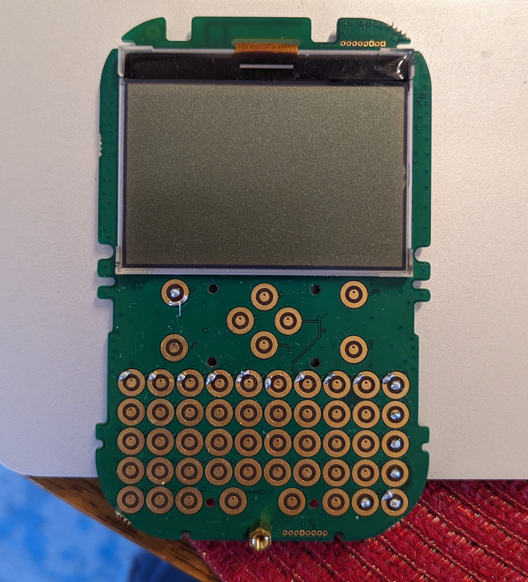
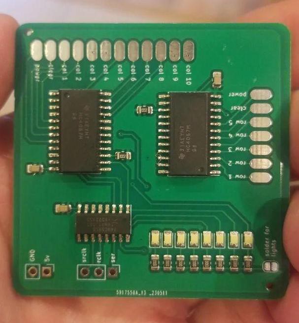 I forgot the mounting hole so there was a final final v1.1.1 board seen below
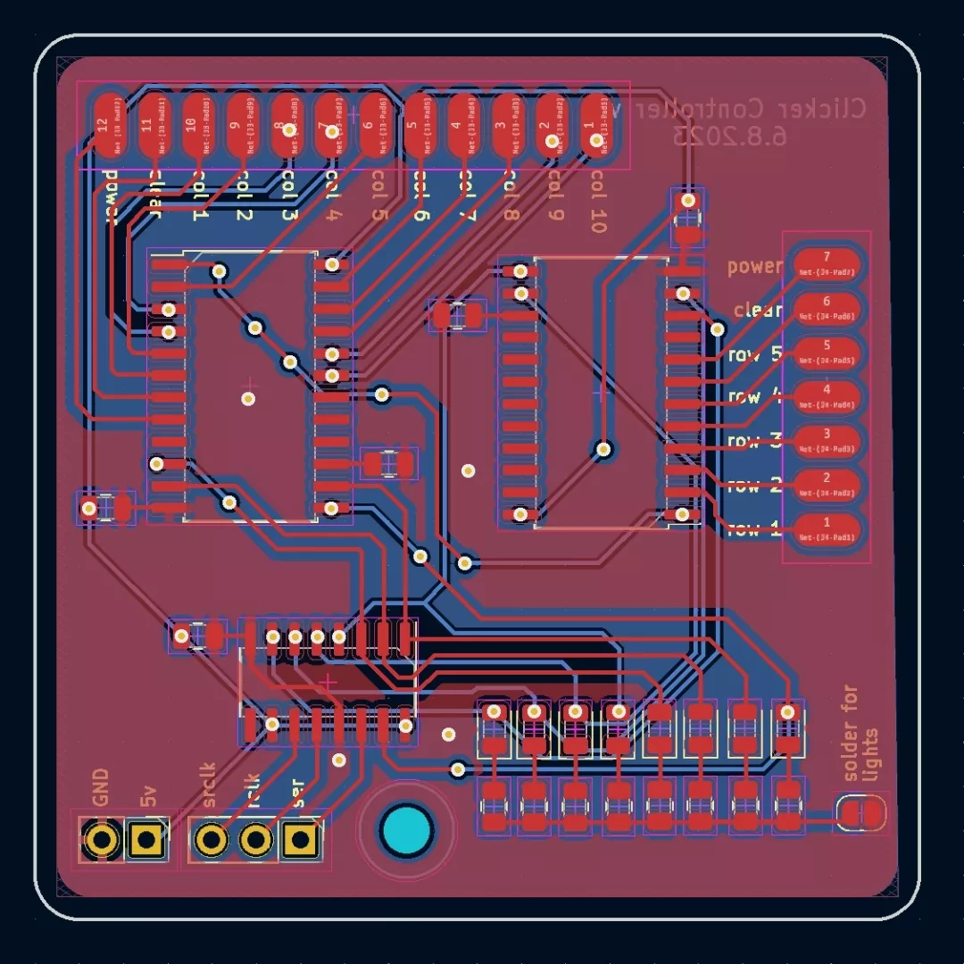
 Matthew Peverill
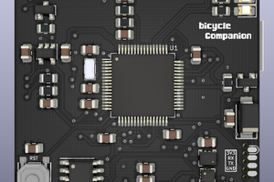
 Matias N.
 Kenji Larsen
 glgorman