mircemk
This time I will describe to you a project where access is made possible in a very unusual way with the help of a flashlight from a smartphone.
In this way, even double protection is enabled, once a password has to be entered in the APK application, and then that information is transmitted using the light generated by the smartphone flashlight, and there is no way to enter it directly on the lock.
I got the idea from Himanshu Sharma's Li-Fi project from where I also used the .APK application, and adapted the Arduino code for this particular project.
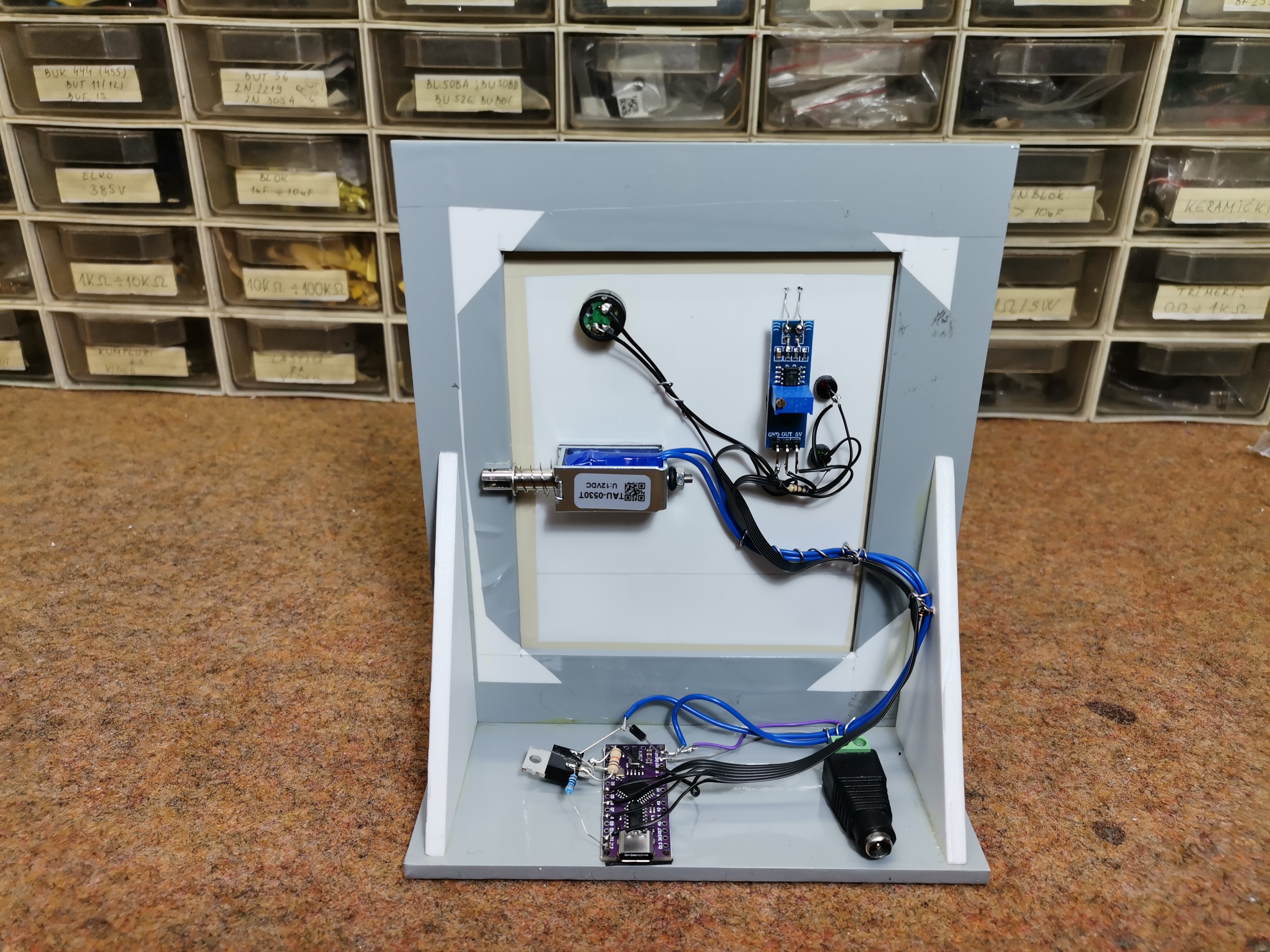
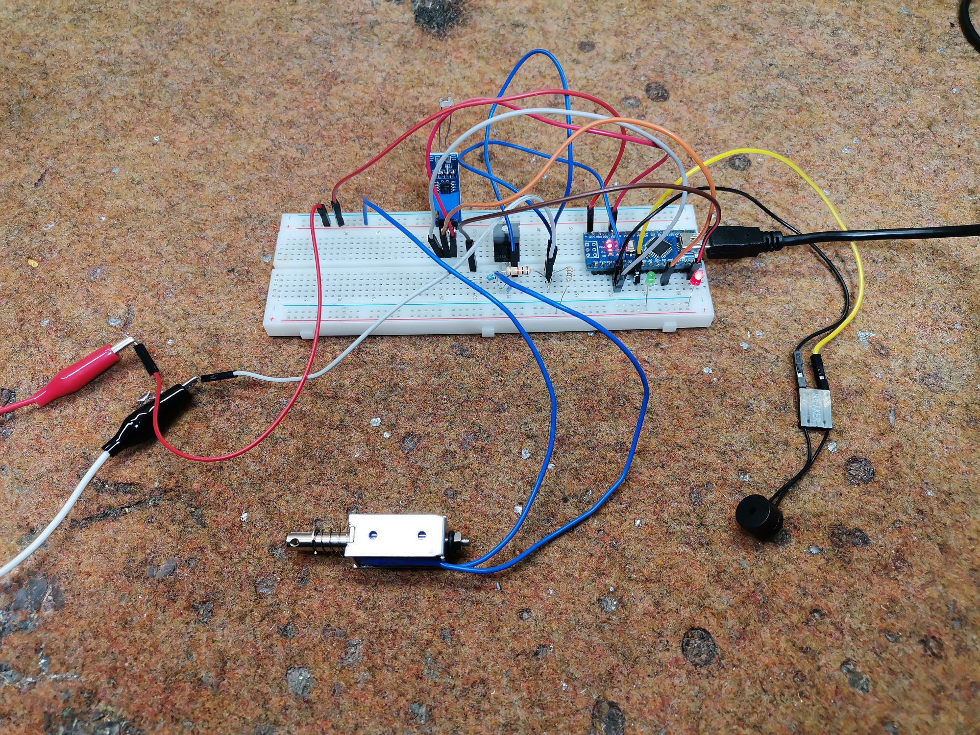
The device is very simple to make and contains only a few components
- Arduino Nano Microcontroller
- LDR resistor module
- 12V Relay
- Power Mosfet Transistor (IRF730)
- Buzzer
- Two LEDs
- and some resistors
On the occasion of the upcoming Christmas and New Year holiydays visit the PCBWay Christmas Big Sales where you will found discounts of up to 50%, as well as many other prizes and benefits. PCBway is one of the most experienced PCB manufacturing company in China in field of PCB prototype and fabrication. They provide completed PCB assembly service with worldwide free shipping, and ISO9001 quality control system. Also, on their site there is an online gerber viewer where you can upload your gerber and drill files to render your board.

The mosfet transistor can be any one with medium or high power, and the relay is designed for 12V operation. As for the LDR module, it contains a LM393 comparator IC, and when the resistor is illuminated, the output voltage should be 0V, and +5V in the dark.
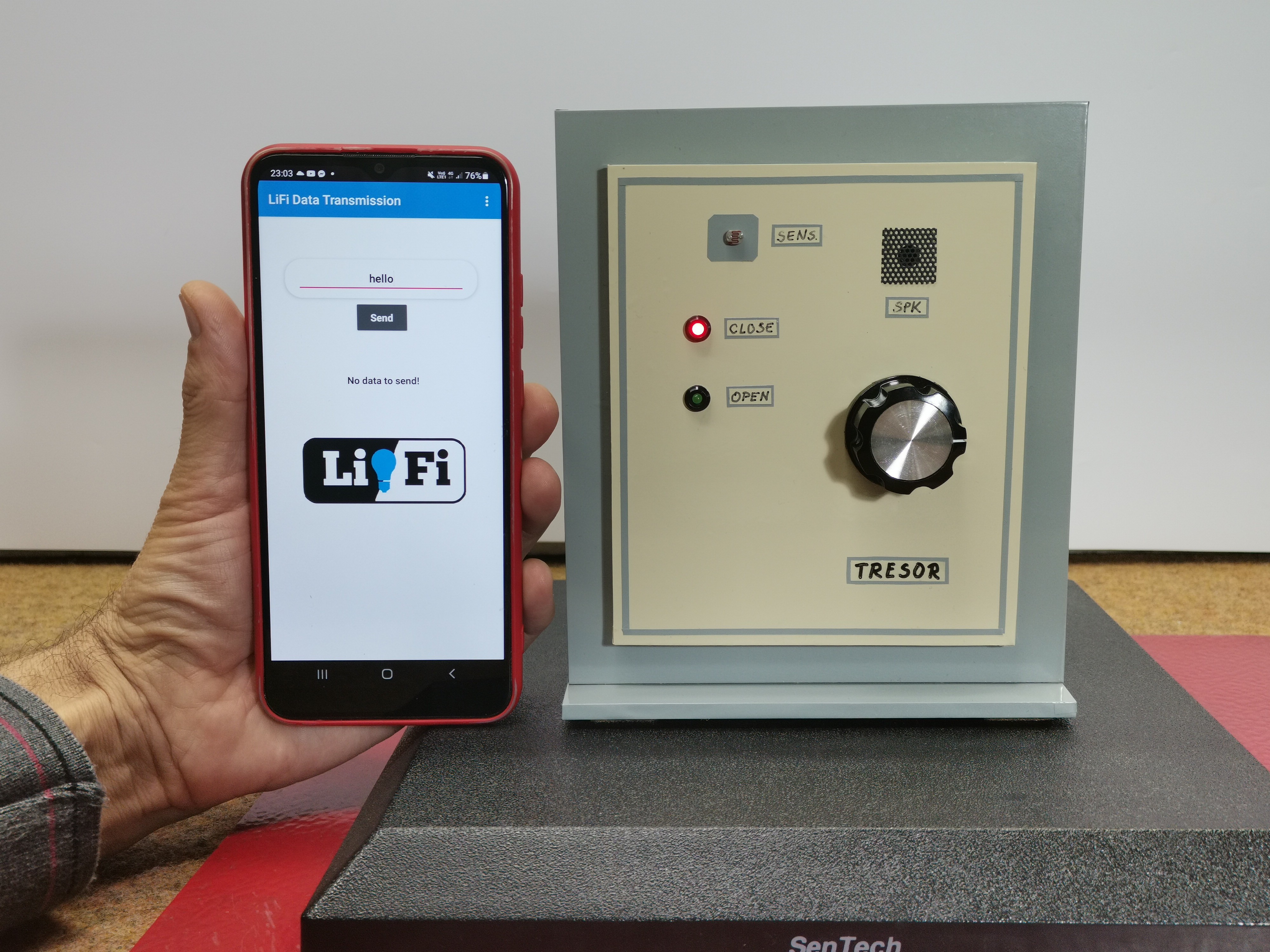
The key to unlock is actually the mobile phone on which the corresponding application is recorded.
First, let's explain how the device works. The smartphone application contains several predefined passwords, and to activate the flash we must enter one of these passwords, in my case it is "hello". Each password generates a flash activation with an exact preset time in milliseconds. On the other hand, the lock is activated only when we bring light to the LDR resistor with the exact time specified in the Arduino code, which should be identical to the time defined in the smartphone application. This time is very precisely defined, so theoretically it is almost impossible to unlock by manually turning the flashlight on and off.

Now let's see how the device works in real conditions:
When switched on, the red LED lights up, which means that the lock is in standby position and is waiting for an opening signal. First, let's try manually turning the flash on and off. As I mentioned before, it is impossible to open the lock this way. Now we will try with the Application. If we enter some random password, the flash is not activated at all. If we enter one of the previously defined passwords that is not common with the Arduino code, the flash is activated, but does not open the lock. Only if we enter the selected password, the door will open, in our case it is "hello". The green LED lights up and the relay is activated for 2 seconds, during which time we can open the door.
And finally, a short conclusion. This is actually not a real Li-Fi communication, it's just a simple light beam with a certain duration, which duration is related to a given operation performed by the arduino. This is just Proof of concept, and in a more advanced case, some useful signal should be modulated in the light, which would then be demodulated in the receiver. This will be the subject of one of my next projects.

 Jithin Sanal
 Saul
Saul