0%
0%
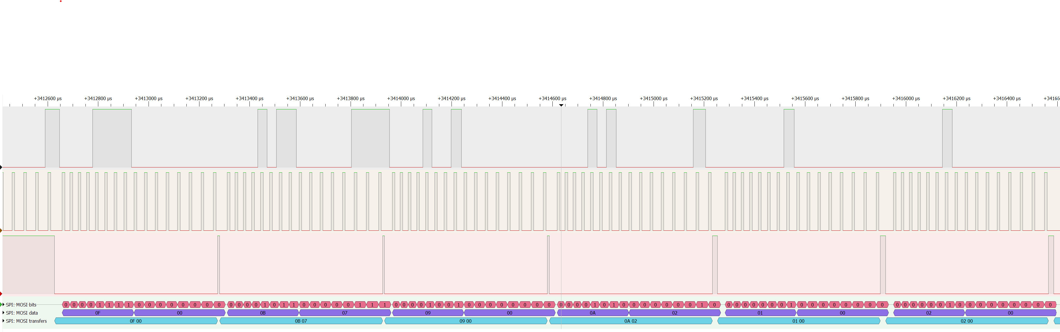
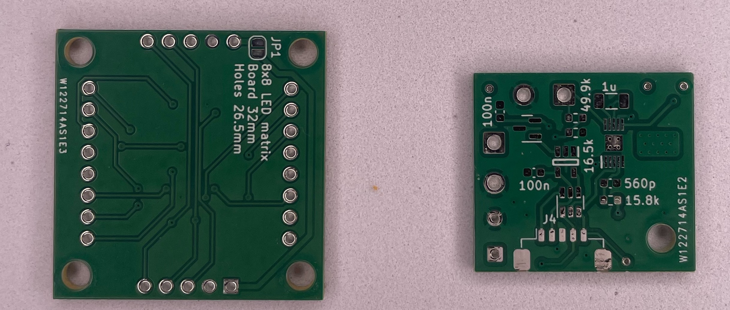
MAX7219 8x8 LED module clone
The FC-16 module is a common 8x8 LED matrix utilising the MAX7219. This project is a DIY clone.
 Stephen G
Become a Hackaday.io member
Already have an account? Log in.
Just one more thing
To make the experience fit your profile, pick a username and tell us what interests you.
Pick an awesome username
hackaday.io/
Your profile's URL: hackaday.io/username. Max 25 alphanumeric characters.
Pick a few interests
Projects that share your interests
People that share your interests


 deʃhipu
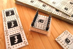
 endevor100
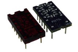
 Alex
Alex