 The Lab Guy
So, we're going to need to do some CAD, therefore we'll need some CAD software.
There are some nice free-to-use choices out there:
- tinkercad.com, easily accessible on the web and runs in your browser
- Microsoft's 3D Builder, built into Windows 10 (and maybe Windows 11 too)
- FreeCAD, a fantastic and powerful CAD tool for pretty much everything. And it is free!
We'll also need to set up our 3D printer or find an online service that will print the parts for us.
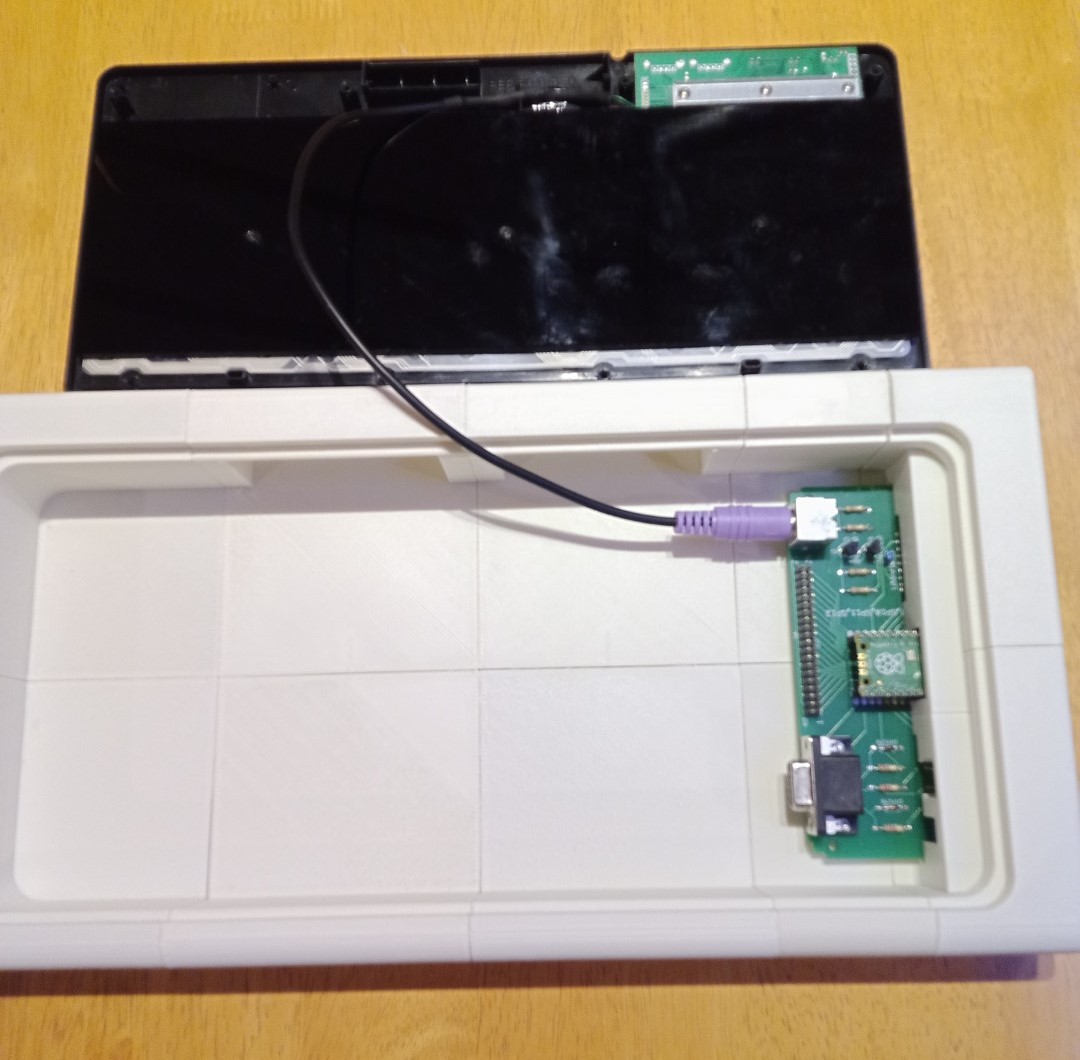
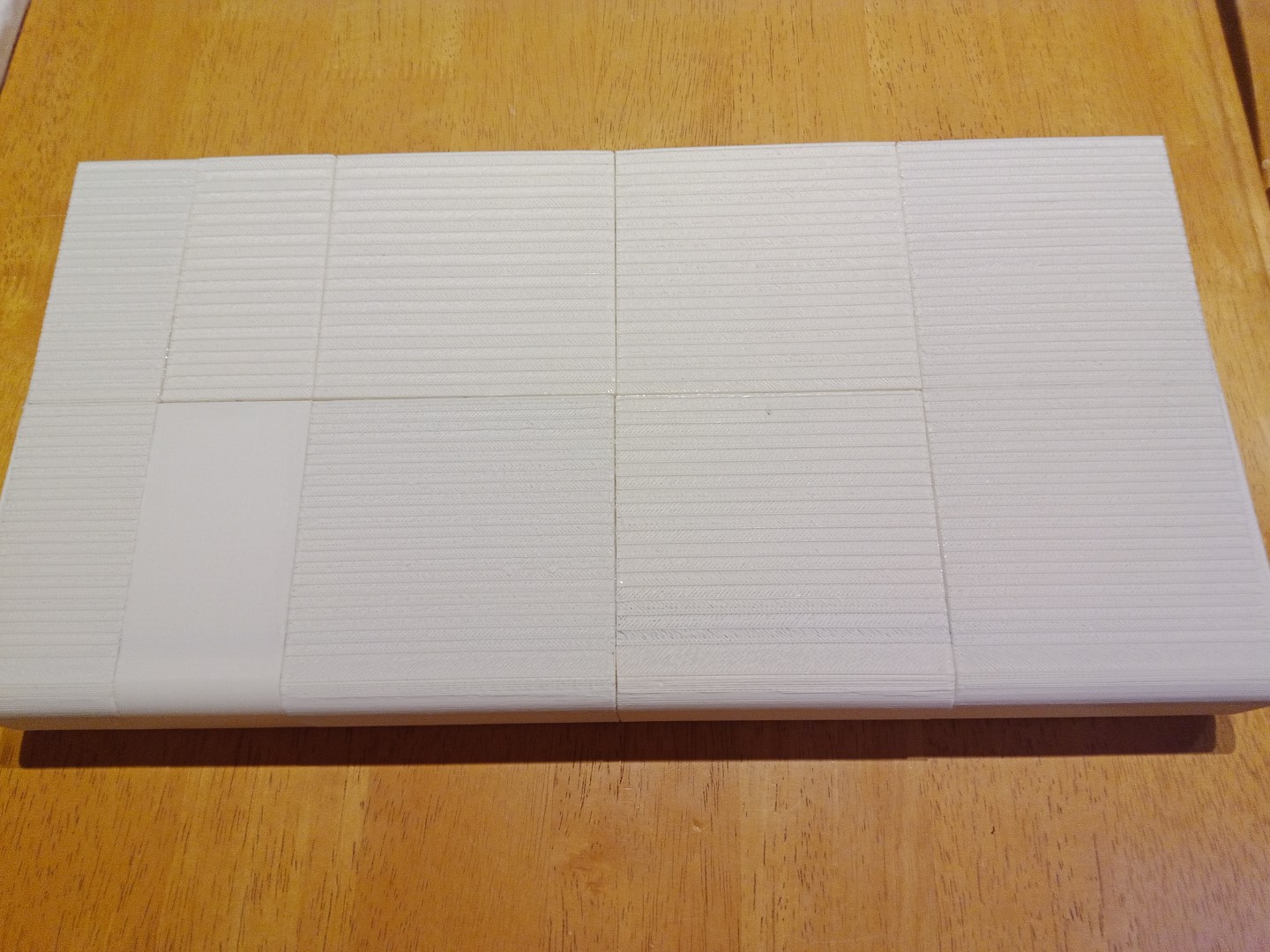
I chose to go with FreeCAD to do the design work and dig out my 10+ year old 3D printer to print it on. The Microsoft 3D Builder tool will be extremely handy to quickly view and make tweaks to the STL files, should there be any weirdness in them due to me being rubbish at CAD.
Irrespective of my choices, the final STL files which can be directly printed on most, if not all, home 3D printers will be available here: RETRO 1 - Home Computer Console


 John
John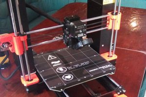
 Patrick
 Christian Lerche