 ElectroBoy
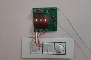
In the previous tutorial we discussed the word organization, setup and configuration of DF2301 Offline voice recognition module. Today we will make a home automation project using the same module with Solid state relay interface for small loads. But first we will try some circuit controlling lights using the voice commands and then build the hardware accordingly. This tutorial has two parts. In the first I will do some tests on the breadboard and in the second I will show the PCB that I have built for Home automation. The reason behind using the solid state relay is to reduce the overall form factor. I want to fit the module and microcontroller in a switch board to control the appliances.

DF2301 Offline voice recognition module has inbuilt commands for lights, fans and we can also record some custom controls to set up other cob lights and small loads. The solid state relay is controlled with TRIAC, which is just a bidirectional AC switch and separate controllers are available there to make them more usable. Transform your concepts into flawless PCBs with JLCPCB's advanced manufacturing expertise. Try now from here just in $2 for 5 pcs of 2layer board.
TRIAC control:
TRIAC is basically a thyristor, which is used to control the AC supply. Either it can turn on/off the load or control the load by modulating the firing angle or we can say dim the overall output. But here in the circuit the TRIAC is used as a simple switch as relay to on/off the devices. TRIAC do not need high power dissipation because it is controlled by firing pulse on gate. And for controlling the firing pulse TRAIC drive circuitry is required, which may need timing accuracy but here we are using an IC(MOC3021) as driver.
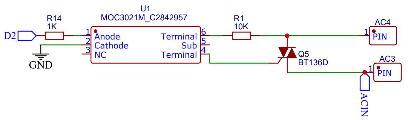
Solid State Relay (SSR) is an electronic switching device that uses semiconductor components to perform the same function as a traditional electromechanical relay. However, SSRs have certain advantages over traditional relays, including faster switching speeds, longer operational life, and the absence of moving parts. Here the switching character totally depends on the circuitry we are using, TRIAC may have different ratings which should be taken care of while designing the circuit for higher loads.
Setup of Voice recognition module Commands:
I Have posted a whole article explaining the commands, wake words and custom words. Check that tutorial from here, in this voice recognition module custom commands can be recorded in any language and then those commands can be used to control the GPIOs of the microcontroller.
The training of the ML module on new custom commands is very easy and all the steps can be found in the previous tutorial. Keep all your custom commands written on a page and train the module in one go. Because there is no option to continue from the next command once exit from the learning mode.
Circuit Diagram for breadboard testing:
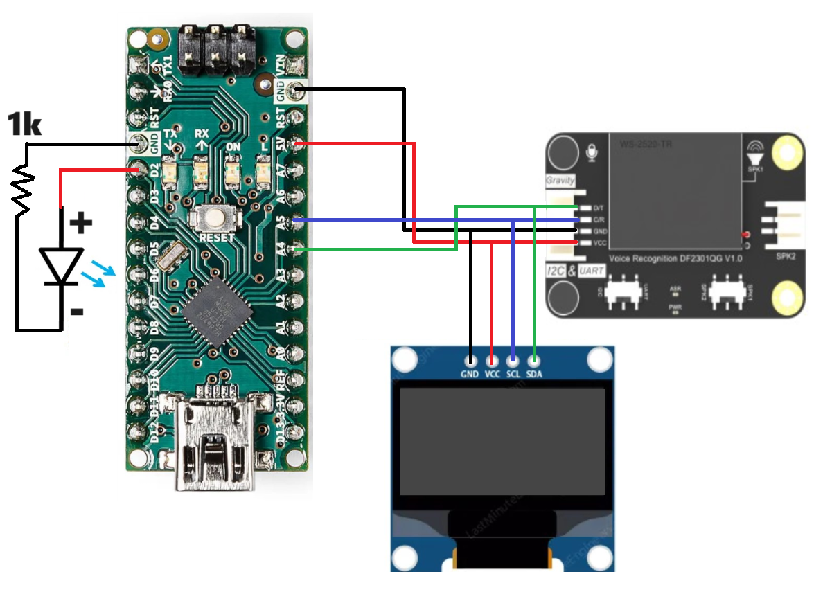
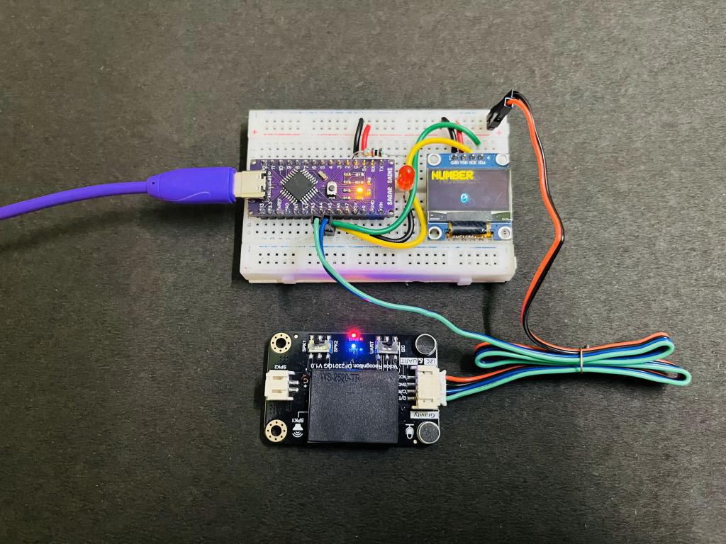
For the testing purpose we are using a breadboard setup, on which Display SSD1306 is connected via the same I2C port in which Module is connected. I2C supports up to 127 devices with different addresses. Whole the system is powered directly by the USB power from the Arduino. A LED is also connected with Digital pin 2 of Arduino Nano. The code can be programmed as per 2 devices here functions to ON/OFF the LED and display some number on SSD1306 display. GND terminal of all the peripherals remains common.
Arduino code for test:
This is the code to test the breadboard circuit only.
#include "DFRobot_DF2301Q.h"
#include <SPI.h>
#include <Wire.h>
#include <Adafruit_GFX.h>
#include <Adafruit_SSD1306.h>
#define SCREEN_WIDTH 128 // OLED display width, in pixels
#define SCREEN_HEIGHT 64 // OLED display height, in pixels
#define light 2 // relay is connected to the digital pin D4
//I2C communication
DFRobot_DF2301Q_I2C asr; // activates the I2C mode of the voice recognition module
#define OLED_RESET     -1 // Reset pin # (or -1 if sharing Arduino reset pin)
#define SCREEN_ADDRESS...
Read more »
 Sagar 001
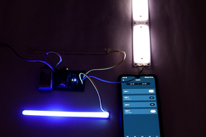
 Jithin Sanal
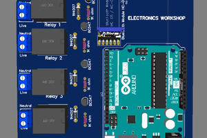
 electronicsworkshops