 tomcircuit
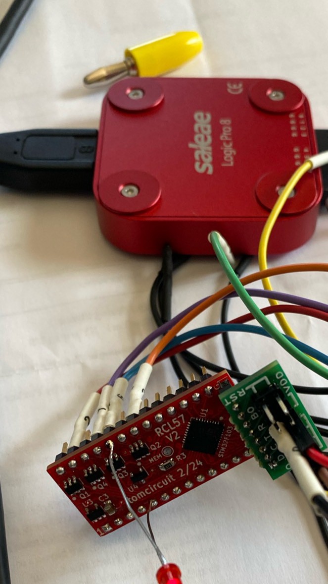
I've assembled four of the rcl57 PCB. Three actually function. The fourth wouldn't connect via SWD to get flashed. Even after replacing and reworking the VQFN36 MCU I was not able to get it to work. So, I have three boards right now, one of which I have setup for test/debug.
With the PCB populated, I can now see the effects of the few off-MCU hardware resources of the rcl57 circuit. One thing I really wanted to look into was the effect using the open-drain Pch MOSFET drivers for segment anode drivers. On the one hand, they can source a lot of current - more than 60mA or so maximum that will ever be needed. On the other hand, with just the PCB and no attached LED digits, I was able to observe that the PMOS segment driver outputs were high longer than the 700us low-going gate pulse. For example, in this screenshot, the segment output registers as "high" to my Saleae logic analyzer for about 1.1ms (top trace):
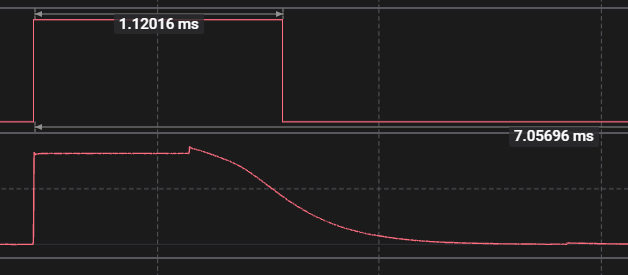
Looking into the analog domain (lower trace), it's easy to guess what is happening: the segment output is slowly discharging into the input of the logic analyzer (high Z input).
When an LED is present between a segment output and a digit sink, the digital pulse width (top trace) is right in line with the gate pulse width - the voltage rapidly falls below 1.6V
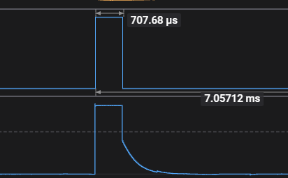
Looking at the analog voltage in this case (lower trace) it's clear what is going on - the LED discharges the drain output until the LED no longer conducts, at which point the residual charge simply leaks away. Therefore, when a segment is to be illuminated in at least one of the twelve digit positions, the segment voltage will discharge quickly through the LED(s). That's good news, and really means that nothing special needs to be done to discharge the segment outputs; the LEDs themselves will take care of this problem for us.
What about 'dark segment intervals' - segment intervals in which no LED in any of the digit positions is illuminated? Well, we're back to a slowly decaying >1ms pulse; there's no low impedance discharge path for segment drive output. This is a problem because the subsequent segment will get enabled after 800us and there will be about 300us of 'overlap' with two segments active at the same time:
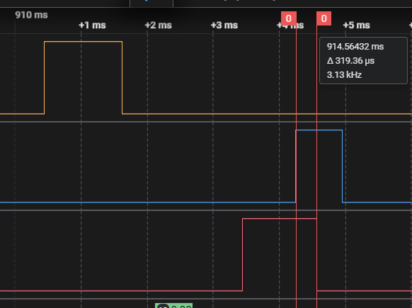
Why could this 'overlap' be a problem? Well, if a dark segment interval is followed by a non-dark segment interval, the residual charge on the 'dark' segment output will dump through the digits that are subsequently enabled. That could end up looking like "sparkle" in the display. Sure, it would be a brief flash, but here's an interesting post on stackexchange that claims that around 150ns of "on" time could be visible.
Ok, well, then why drive inactive segments at all? Why I am paying so much attention to the logic analyzer's "digital interpretation" of the decaying voltage on the segment driver outputs? The answers to both of these questions are related, and all revolve around the fact that the segment driver outputs are also used for reading the keypad. If the segment isn't driven at all, then the corresponding row of the keyboard cannot be read. If the slowly decaying voltage were to take too long to decay, it could end up being "high enough" when subsequent segment keyboard reads take place - so keys from more than one row could potentially be read simultaneously, leading to strange behavior. The logic analyzer digital interpretation of the voltage indication an idea of what the STM32F103 GPIO pin would read.
Ok, so for segment intervals in which there is no display activity, we need only to read the keyboard. So far, my plan to achieve this is the following: as the display update function (hw_display_update) loops though the 8 segment intervals, if no digits are to be activated during this segment interval, the segment output is driven for only 100us, rather than 700us. At the end of the 100us, the keyboard row lines are read, and then the segment output is disabled for the remainder of the 800us segment interval. Even with only 100us of "pumping", the unterminated segment output ends up registering high for nearly 600us:
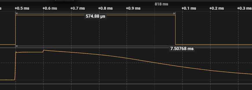
So long as this remains less than 900us wide, there's no danger of reading two rows simultaneously. Hopefully this works out. I don't really have any better solutions in mind...
Discussions
Become a Hackaday.io Member
Create an account to leave a comment. Already have an account? Log In.