 tomcircuit
At this point the display is working quite nicely - segment drivers are driving, current sinks are sinking, LED’s are emitting. Joy.
Tests with the keyboard, however, have been less successful. That slowly delaying segment driver output, and what I can only assume is a leakage path across the FETs, results in a very ugly multi-voltage waveform. No issue for the LED displays - LED's are current, not voltage, controlled beasties, so they light up when the should and stay dark otherwise. But, this leakage path voltage is a big problem for the keyboard column inputs - when a key is pressed, it is typically registering in several rows. All because the row (segment) voltages are interacting with one another; they are not ‘crisp’ CMOS levels
I spent several hours thinking about how to tame the segment voltages. An initially promising solution was adding N MOSFETs to make CMOS P-P segment drivers. Challenging from a PCB area standpoint because it would double the number of MOSFETs but ultimately not a solution for the D and DP segments, because they are shared with the current sinks for D1 and D12. Driving either of these “segments” low whilst another segment is high would illuminate that segment on D1 and D12, very brightly.
I thought about how the TI engineers must have solved this. I concluded that this melange of voltages is only a problem for reading keys. The beautiful display was confirmation of this. So, rather than trying to tame the segment voltages, I shifted my focus entirely towards reading the keyboard columns. A “simple fix” would be to make the VIH threshold much higher than the garbage on the un-driven segment outputs. Easy to do in a custom IC, but not possible with a standard MCU. Reading the column voltages with an ADC, however, is the next best thing.
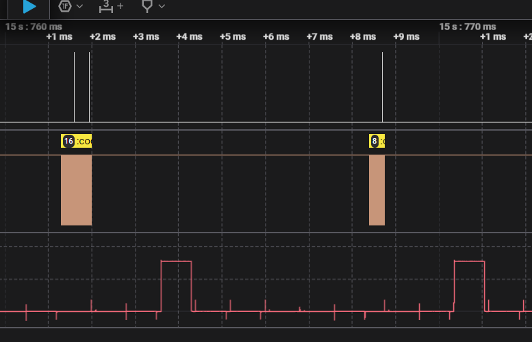
I experimented with the ADC but quickly discovered that the STM32F103 MCU doesn’t allow the GPIO internal pulldowns to be enabled when a pin is configured as an Analog Input. So I added some leaded resistor pulldowns on my test setup. Voila! My random selection of 1.8K and 5.1K pulldown resistors dissipated all the nasty voltages on 6 of the 8 segment lines when a keyswitch in those rows is closed - there's a nice, crisp 3.3V pulse for the 700us active segment interval.
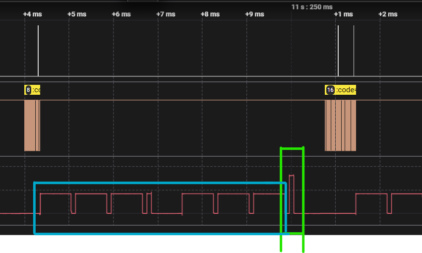
When the columns are switched to the shared lines (D+D12 and DP+D1) the voltages are still ugly - this is unavoidable because of the shared digit cathode and segment anode arrangement on those two digits. The "high" level (green box, peak around 3.3V) is the segment driver row being read through a key column. The "medium" level (blue box, peaks around 1.7V) are the segment drivers for the other rows being read via the shared segment-digit path into the key column input. For these two rows (segments D and DP, rows 7 & 8 on the keypad) even with the addition of column input pulldown resistors, I will have to use the ADC to manually threshold the signal to something above, say, 2.5V. (Note: I suppose that I could add a series diode to the segment D and DP outputs to reduce this residual voltage to something below the MCU VIH threshold, but that means even more parts on the PCB...)
Unfortunately, this means a new PCB, to add pulldowns on the K1-K5 inputs… I can prototype with the pulldown resistors tacked to the bottom of the TI PCB but I'm not super-happy with that as a long-term solution.

Discussions
Become a Hackaday.io Member
Create an account to leave a comment. Already have an account? Log In.