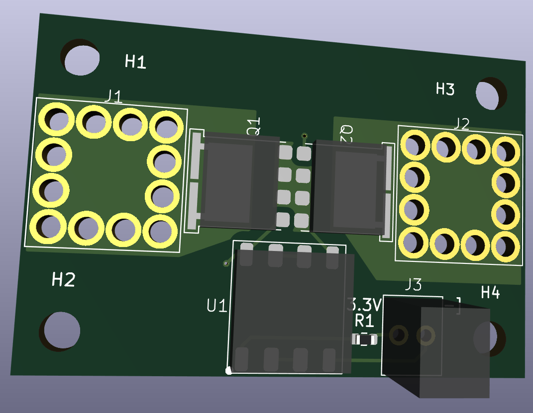
I wanted to build a high current isolated switch, and also test the footprints for the switching mosfet (Vishay SQJQ130EL, 445 amps) and the Wurth S93513 press fit screw terminal (192 amps).
It is based on a Broadcom ASSR-V621 dual channel photovoltaic MOSFET driver. You bias the LED on one side of the driver package, and on the other, the photodiodes generate ~7 V for the mosfet gate source voltage. In my circuit, I chained together the photodiodes so that you get ~14 V for Vgs, to reduce the on-state resistance.
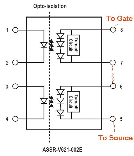
The mosfets are placed source-to-source to prevent the source-drain diodes from conducting.
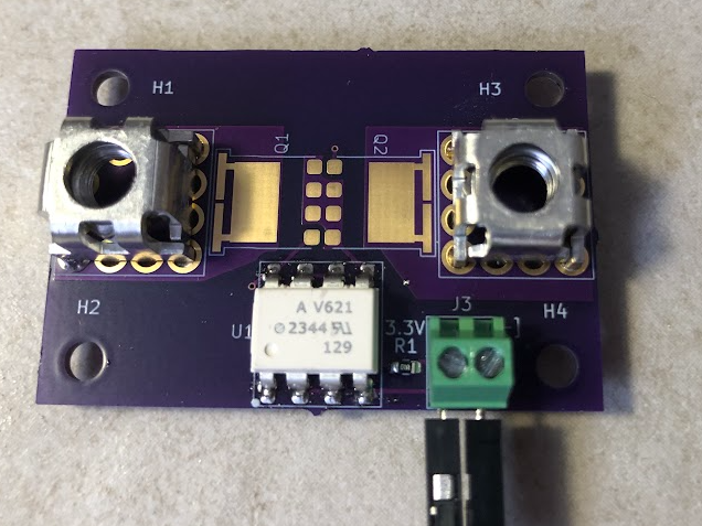
Here is a photo of the board with no mosfets (to double check the polarity of the gate voltage, and check the fit on the press terminals).
Here is the board with the mosfets populated...
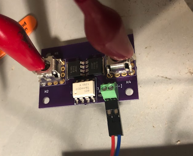
With the 3.3 V applied to the one side of the switch board, and 2 k resistor to ground, I measured the delay/rise time to turn on the fets. At about 7 ms, and an expect capacitance of 40 nF for the mosfets, this is about right.

Turn off time was about 262 us, which was a little better than expected.

Discussions
Become a Hackaday.io Member
Create an account to leave a comment. Already have an account? Log In.