 Bharbour
The IS31FL3730 driver chip has worked well for me on several projects, driving large multicolor matrix LED displays. It will support two matrices of up to 8x8 LEDs. Previous projects have used the larger LiteOn LTP2588AA displays which have a red and green LED at each dot, allowing 3 color choices per dot. On the driver chip, pins are shared between both LED matrices, with matrix 1 driving displays with their cathodes on the column pins and matrix 2 driving displays with their cathodes on the row pins. The larger displays have separate pins for the red and green arrays, but both sets have their cathodes on the column pins. By electrically rotating the second LED matrix, and connecting it's rows to the column pins on the driver chip, it appears to the chip that it's column pins are driving a common anode display. This rotation also makes the displayed characters rotate 90 degrees.
Inside the driver chip, there are two pairs of 11 8 bit registers, because the chip can support up to 11 column displays. I am only using 8 columns for both colors in the LTP2588AA displays. Each bit in each column register corresponds to a row in that column. A 1 in column register 2, bit 3 results in the LED connected to column 2, row 3 lighting up. Both matrices in the chip share the configuration, so the driver chip needs to be configured for 8 columns x 8 rows of active space.
Translation from ASCII characters to LED on/off data is done in the driver software that I wrote. An 2 dimensional array is used for this translation. One dimension is indexed by the ASCII character value and the other is the column number. The data values from the array get loaded into the column registers in the driver chip. Since matrix 2 display is rotated electrically, you need to rotate the translated LED data so the characters appear in the right orientation. It would be possible to rotate the matrix 2 data for each character on the fly in the driver, but this would slow things down quite a bit. A second array with the rotated values is a simple solution to this at the cost of an extra 768 bytes of storage space. Both of these arrays are constant values, stored in program memory space.
Shopping around for smaller matrix displays, I found the LTP757 displays which are 0.7" high characters using a 5x7 matrix. That series is available in a few different colors, but only one color per display. Instead of driving a second matrix on the same display, the new board drives 2 displays from one driver chip. The same driver trick is used to correct for the electrically rotated character in the second matrix.

The 2C address for each module is selected by populating jumper 1 through 4. There are only 4 address choices available for each driver chip. I2C bus termination can be applied by populating the resistors R1, R2 or not.
Very little modification to the driver software was needed to support two digits instead of two colors per digit. Mostly, it was removing support for the color attribute. Minor changes were needed in the initialization code so that each driver chip only got initialized once. Upon testing, the new displays were much too bright, so the PWM value got adjusted downward so the brightness range makes sense. Code that actually loads the column registers for each character now senses whether the selected character index is odd or even. Even character column data gets loaded into matrix 1 registers and odd character column data gets loaded into matrix 2 registers. Since the new displays are 5 columns x 7 rows, while the original displays are 5 columns x 8 rows, a few of the character generator array values need to be adjusted. Digits and upper case alpha characters are fine, while lower case descender characters like g, j, p, and q need to get shifted up a row to be complete.
The driver software makes all 5 of these displays appear to be a single 10 character display. The...
Read more »
 Louis Beaudoin
 zakqwy
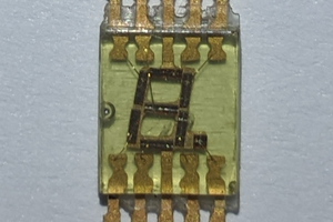
 Robert
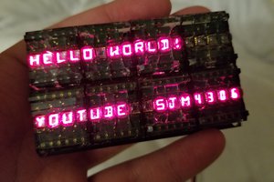
 sjm4306