So here we are two weeks later. Each module of 2 x 6 has taken me an evening to put together. (Well, 1-2 hours but each one is getting quicker and neater). As you have seen in the first part, I went for a construction that's cheap on parts but big on time, which is OK because this is very much a hobby project.
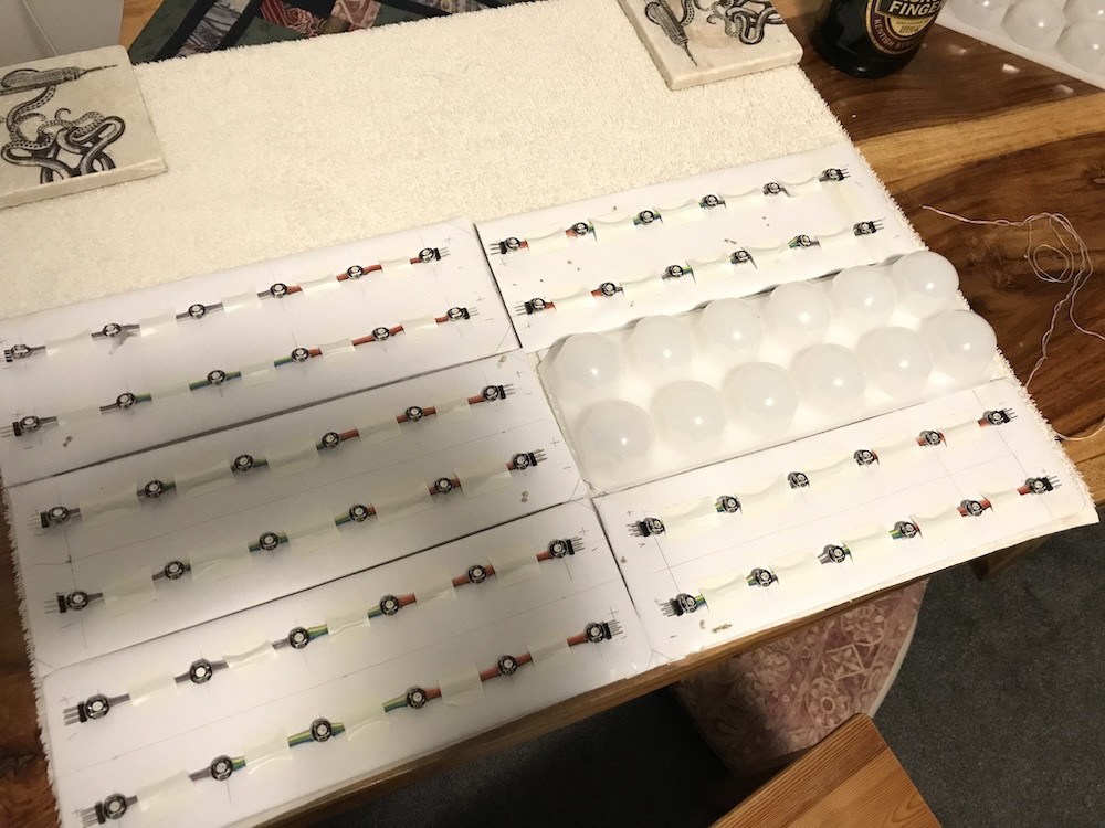
Here's the point where I had six modules done (but not wired together). I was keen to connect them and make sure they worked before going any further. This meant deciding how to fasten them together and how I wanted to mount them on the wall. I went for stitching them onto something flexible rather than something rigid like a piece of board, so that the whole thing will be lighter and roll up for storage. I didn't have a bedsheet that I wanted to sacrifice but did have plenty of old towels, so used one of those. I cut and hemmed it to the right size (21" wide) and stitched each of the modules onto it. The ice-cube tray is just placed in position in the photo
So onto the ice-cube trays. Fortunately the store still had some more (They're on offer and are not sold out yet) so I picked up another half dozen. That means I have enough to build my 12x12 display as originally planned. (I've since thought about extending this to 12x18, so I'll see whether they have another half dozen next time I visit.)
They have a rim/lip which needs trimming off to allow the trays to butt together with the bubbles at the right pitch. The little circular saw blade for the Dremel made very short work of those:

... and if any more material needed taking off, and to straighten out any unevenness, 40-grit works very quickly.

I also had to buy more pixels. When I was first inspired to do this I was thinking 8x8 and so I only bought 70.

I bought another 100 for about £30.
These pixels are amazing. For the uninitiated, each 'LED' is actually three LEDs, in this case a red, a green and a blue one, plus a little controller chip. You send it a small amount of data and the controller will manage the three LEDs to make the colour you want, and will maintain that colour as long as you keep supplying power. Each pixel has a single data line in and out and it does a very clever trick that means that you can daisy-chain as many of these as you like.
They're sometimes called 'addressable' but I don't think that's accurate. You can't just send data to a specific pixel, you have to send the data for all of the pixels up to and including the one that you want to change.
Here's a close up. Under the circular lens (which is less than 5mm diameter) you can just about see three darker shapes which I think are the LEDs. The 'squashed bug' in the middle is the controller chip. All of this is within a little square package, and I'm buying these particular ones already mounted on a small circular PCB containing some supporting passives as well as giving you some very convenient solder pads on the back. They arrive scored so that you can snap them off individually or leave them in groups.

Now onto the software side. I have a lot of ideas for things to run on this display, but I wanted a demo for testing that was a little more impressive than the chasing lights I presented in the last project log.
I spent a little time with a Pico and a compact 8x8 matrix and managed to get a 'plasma' demo running. Nice!

Today I made the final connections on my work-in-progress display and powered it on. Predictably, not all lights lit, and some were a bit intermittent. The latter problem was a whisker of wire intermittently shorting out two pads on the back of one of the pixels. The other problem (after some checking and re-checking my connections) was a software problem. Although I'd made my plasma code configurable, I'd been developing it using an 8x8 matrix and forgot to reconfigure for 6x12, and so only 64 of my lights lit. D'oh! That was easily fixed.
I'm thrilled with this. It looks great (LEDs always look better in person than on camera don't they?)
So for the next few evenings I'll be making more of my modules and expanding this to 12x12.
Power is a concern. These pixels can draw up to 60mA at full brightness (I haven't measured the particular ones I'm using). That doesn't sound much but multiply that by 144 and that's 8.6A (or by 216 for my possible future expansion to 12x18 and that's nearly 13A.)
I'll never be turning on all pixels to bright white at full brightness and for most of my ideas, not all pixels will be lit at once. So in practice the power requirement will be much lower than the figures above. But as I add to this display and get a few more demos coded, I'll be measuring current to see what we're really dealing with.
Discussions
Become a Hackaday.io Member
Create an account to leave a comment. Already have an account? Log In.