 psemportugal
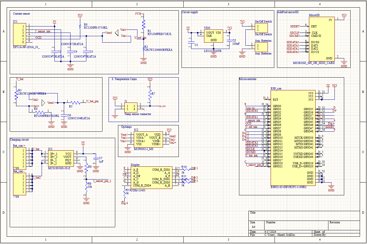
The PCB design for this project was crafted using Altium Designer, a renowned software in the field. While not free, Altium Designer stands as one of the most widely utilized PCB CAD tools among engineers and designers globally.
Additionally, a micro-SD card is integrated to consistently store data acquired from the utilized sensors.
For the microcontroller, we opted for the ESP32-S3-WROOM-1-N8R2 due to its integrated antenna and comprehensive peripheral set, catering to project requirements seamlessly.
Given that the GPIOs are rated for a maximum voltage of 3.3V, all sensor connections have been meticulously adjusted. This adjustment encompasses power supplies and voltage dividers to ensure that the output adheres to this voltage requirement.
In addition, a 4-digit display is used to show possible relevant information such as temperature data.
In the following image we see the entire PCB layout.
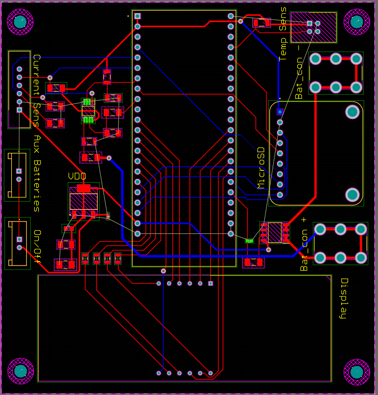
The minimum track width used was 0.3mm because of the density of connections and the current needed. For the power traces the width used was 0.5mm, except for the traces that connect to the batteries, where a width of 0.7mm was used, since a relatively large amount of current will flow from the batteries (between 20A and 25A, under nominal conditions), these traces need to be as thick as possible on the PCB.

 Pariv
Pariv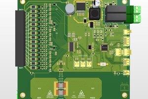
 Onur Şurgun