mircemk
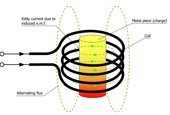
This device consists of a coil of wire through which a high-frequency alternating current (AC) is passed, and this coil generates a magnetic field around it. When a conductive material is placed within this magnetic field, it induces electric currents, known as "eddy currents," within the material. These eddy currents generate heat due to electrical resistance in the material, causing it to become hot.
These days, I received this device as a gift from a friend who is a dentist by profession, because it had been sitting in his garage for several years and he had not used it. I immediately decided to study it in more detail so that I could find some application for it. Analyzing the outside, it is immediately seen that it is most likely an induction heater, especially considering this copper coil made of a pipe with a diameter of 7mm.
But to look inside, I first have to remove these cooling fans. Now the PCB is clearly visible and so we can start the analysis. The device contains a very small number of components, including 6 power mosfets IRFP260 mounted on a heatsink, several high-quality MKP capacitors connected in combination, several fast and zener diodes, and two large chopper coils. Here you can see that the device is powered with a voltage of 48 Volts and a current of up to 50 Amps, which by simple multiplication we can calculate that it is a device with a power of 2500 watts or 2.5 kilowatts.
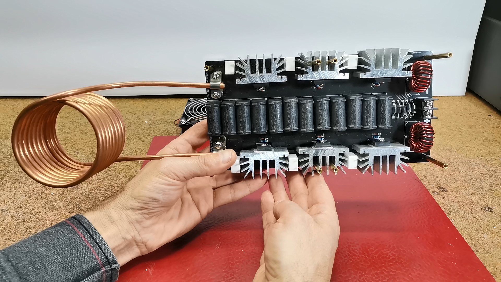
And so according to the components, it is not at all difficult to conclude that it is a standard Zero Voltage Switching (ZVS) driver that is used to drive high-frequency resonant converters, typically for applications like induction heating, power supplies, and ballast lighting. According to the size and shape of the coil, we can conclude that it is an Induction Heater with high power. The mosfets are interconnected in two groups, each of three in parallel connection, so that they can withstand a higher current.
First I will put the fans back in place and test the unit.
And as you can imagine, it is very difficult to find a power supply with these features. Nowadays switching mode power supplies are widespread, but this is a special case where extremely high currents flow. In such conditions, these power supplies often experience instability during operation, change in characteristics, and even damage to the power supply.
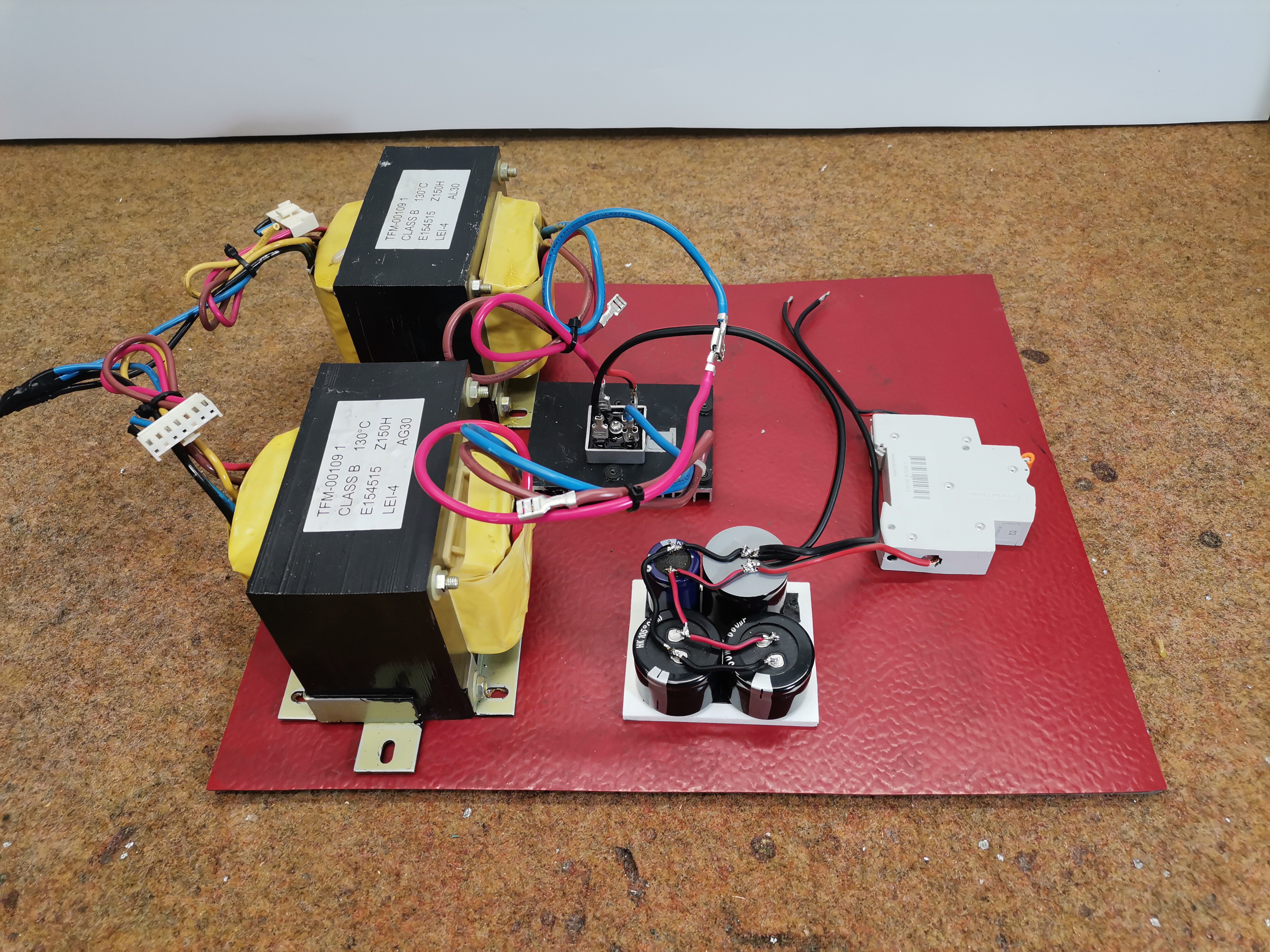
Fortunately, I had two powerful transformers with a power of 1500 watts each, and they have a secondary voltage of 17V. These are transformers taken out of an old failed UPS unit. As you can see, I connected the primaries in parallel, and the secondary windings in series, so at the output I got an AC voltage of 34 V / 3000 watts. This is exactly what I need, because after rectifying and filtering the alternating voltage, I get 45 volts DC voltage under load.

As a rectifier, I use a Gretz type KBPC 5010 designed for voltages up to 1000V and a current of 50A. Next is a filter of several electrolytic capacitors with a total value of 4000µF. For safety, I also installed an automatic fuse, initially with a value of 20 Amps
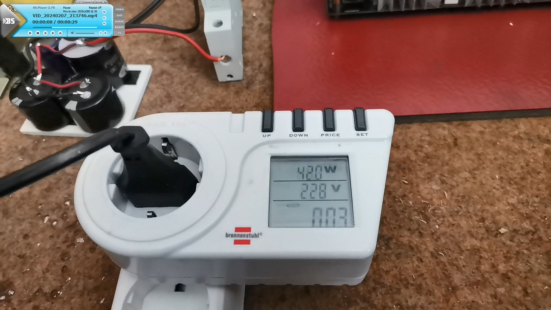
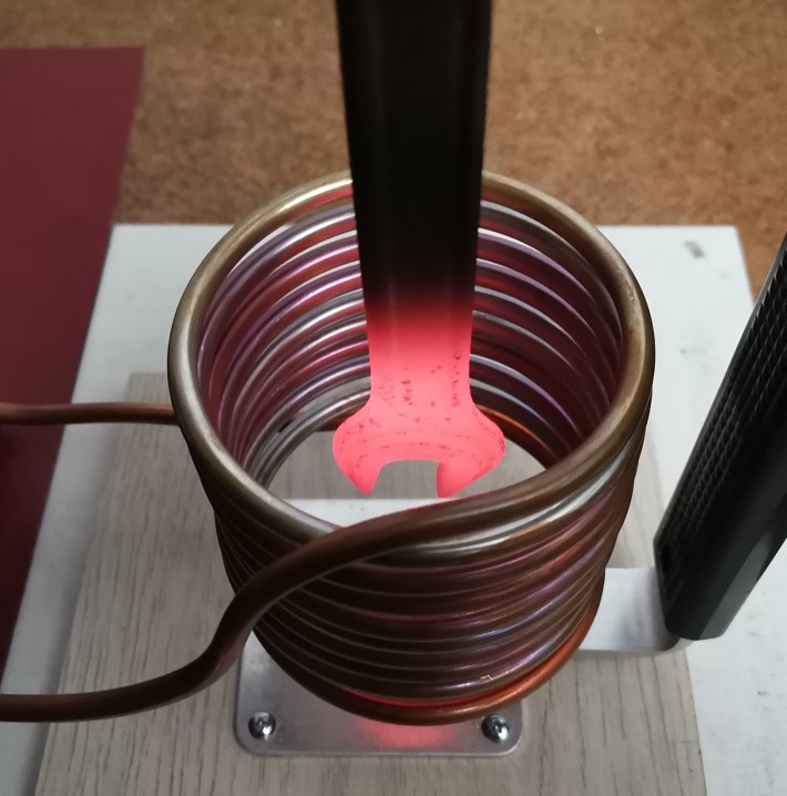
And now let's see how the device works in real conditions. During the test I will use first small and then larger objects and at the same time I will read the total consumption with Wattmeter, because at the moment I do not have an Ammeter for large currents (so-called current clamp).


And finally a short conclusion.
The device is solidly made, and for a power of up to 1.2 kilowatts, cooling fans are not needed at all. I actually didn't use the fans during testing. This device is sold online for a price of about $100 which is actually some real amount. A much bigger problem is the power supply for it, so if we don't have an alternative like in my case, the cost of the power supply would several times exceed the price of the device itself. This induction heater can be used with graphite crucible for smelting gold,...
Read more »
 Nick Sayer
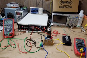
 Collin Matthews