ken.do
-
Project specific Arduino projects
02/17/2017 at 22:52 • 0 comments![]()
Most of these projects averaged about 2 hours, except for dumdum detector where each part took about an hour.
The next Arduino project series will be a little more specific to some of the other projects I want to incorporate the Arduino Nano. I will link to them here.
Thanks for checking out this project!!
-
Using an Arduino to flash ESCs
02/02/2017 at 04:20 • 0 commentsBy 'flash' I don't mean what I did here...
I am trying to flash some escs with the right firmware to make them be able to reverse the direction of the BLDC they are driving... maybe it's a myth or a pipedream, but this is my adventure...
Update:
I got my BLDCs to turn in one direction, but one direction only. Not sure if it the firmware (trying to use SimonK latest 'reverse') or my ESCs or something else...
Tools and Supplies::
KKMulticopter Flash Tool - Flashing program
ESC - I'm using a Q-Brain 4-in-1 20A, because it is what I had and it already had the SimonK Bootloader)
Arduino Nano
Some male-to-male jumper wires
So the idea here is to make my Arduino Nano into a USB-run, one-wire ESC programming tool. According to what I have been able to glean from the interweb of assorted tutorials, all you need to do is plug the ground and signal wires from the ESC into the GND and D3 pins of the Nano. I also plugged the positive VIN on the ESC into the 5V pin on the Nano. This seems a lot easier than trying to figure out the pads on the ESC, making a tool or soldering wires to the ESC to program it with a USB ASP Atmel programming tool.
1. Download KKMulticopter Flash Tool
- check!
2. Connect to Arduino
Start up KKMulticopter Flash Tool (KKMFT) without your Arduino plugged in.
Plug in Arduino via USB. KKMFT should recognize it and make the required adjustments of COM port and baud settings.
- programmer option should be 'Arduino'
- port option should be 'USB'
3. Choose your controller - should be 'atmega 8-based brushless esc' option
4. Choose the latest firmware version with the word 'reverse' in it under the 'firmware' option
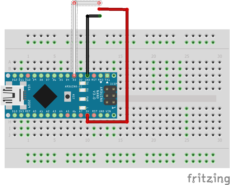
5. Hook up Arduino to ESC cable::
![]()
The white wire - from D3 to ESC signal
The red wire - from 5V to ESC positive
The black wire - from GND to ESC ground
6. Click on the green circle button to 'flash firmware from internet'
That should do it?
We will see when I get some motors hooked up tomorrow...
-
I2C shenanigans
01/31/2017 at 14:39 • 0 commentsI want to use sensors. Probably more than one. So do you.
New to I2C (Inter-Integrated Circuit) communications, the best place to start was a simple sketch that looks for I2C devices/connections. Without knowing if your device/connection is recognized, you may be failing and not understanding why. Often I think that I have done something wrong to find out (much) later that a device or component is malfunctioning. This code shows it's results in the serial monitor when run.
// --------------------------------------
// i2c_scanner
//
// Version 1
//    This program (or code that looks like it)
//    can be found in many places.
//    For example on the Arduino.cc forum.
//    The original author is not know.
// Version 2, Juni 2012, Using Arduino 1.0.1
//     Adapted to be as simple as possible by Arduino.cc user Krodal
// Version 3, Feb 26  2013
//    V3 by louarnold
// Version 4, March 3, 2013, Using Arduino 1.0.3
//    by Arduino.cc user Krodal.
//    Changes by louarnold removed.
//    Scanning addresses changed from 0...127 to 1...119,
//    according to the i2c scanner by Nick Gammon
//    http://www.gammon.com.au/forum/?id=10896
// Version 5, March 28, 2013
//    As version 4, but address scans now to 127.
//    A sensor seems to use address 120.
// Version 6, November 27, 2015.
//    Added waiting for the Leonardo serial communication.
//
//
// This sketch tests the standard 7-bit addresses
// Devices with higher bit address might not be seen properly.
//

#include <Wire.h>


void setup()
{
  Wire.begin();

  Serial.begin(9600);
  while (!Serial);             // Leonardo: wait for serial monitor
  Serial.println("\nI2C Scanner");
}


void loop()
{
  byte error, address;
  int nDevices;

  Serial.println("Scanning...");

  nDevices = 0;
  for(address = 1; address < 127; address++ )
  {
    // The i2c_scanner uses the return value of
    // the Write.endTransmisstion to see if
    // a device did acknowledge to the address.
    Wire.beginTransmission(address);
    error = Wire.endTransmission();

    if (error == 0)
    {
      Serial.print("I2C device found at address 0x");
      if (address<16)
        Serial.print("0");
      Serial.print(address,HEX);
      Serial.println("  !");

      nDevices++;
    }
    else if (error==4)
    {
      Serial.print("Unknow error at address 0x");
      if (address<16)
        Serial.print("0");
      Serial.println(address,HEX);
    }
  }
  if (nDevices == 0)
    Serial.println("No I2C devices found\n");
  else
    Serial.println("done\n");

  delay(5000);           // wait 5 seconds for next scan
}
Not only can you proceed with the sure knowledge your device is connecting, you will also know where it is connecting. The address of the device/module/connection is necessary in most sketches to make use of it.
I get a message like this:
****
Scanning...
I2C device found at address 0x68 !
done
****
One of the common issues with learning Arduino is not realizing that you need to make changes to most sketches to make them work. Read the comments, follow the tutorial exactly if there is a good one.
Sometimes it may be a good idea to make a physical list of the variables you will be using and the pins to which you want to connect. This way, when you are looking through the code, you can easily identfy potential issues.
-
I went to the Dark Side...
01/29/2017 at 16:15 • 1 commentI missed a day. I went to the dark side. They have pi there.
Raspberry Pi has a place in my heart... It is the gadget that started my journey into the world of electronics. I made me feel like I could do it without any formal education. I was looking for ways to automate a fodder sprouting system to feed my milk goats (seriously, for real). Another story, another day...
ANYWAYS, long story short, I had a show and tell and wanted to do a slide show, so I used my Pi B and this touchscreen setup to make it go. Again, tutorials that work are my favorites. This project was built using this instructable.
Finished project::
It was very straightforward:
1. Start with all the regular Pi setup stuff.
- flash an OS image (I used Raspbian Jessie)
- update to latest distro
2. Install feh
sudo apt-get install feh
3. Install screensaversudo apt-get install xscreensaver
All the screensaver configuration is done in terminal on a command line. The config I used wasfeh -Y -x -q -D 8 -B black -F -Z -z -r /media/And it should roll...
There is a manual accessible by using the 'man feh' command..
4. Configure Pi for touchscreen
I had to add a step to get my screen to work, modifying the config.txt file in the boot directory of my Pi.
cd ..
cd ..
cd boot
sudo nano config.txt
And the lines I added were:max_usb_current=1 hdmi_group=2 hdmi_mode=1 hdmi_mode=87 hdmi_cvt 1024 600 60 6 0 0 0Over all, took me about 45 minutes, most of which was spent waiting for pi update and installs...Thats ok cause I spent that time in the most constructive way possible; playing slither.io. Look for me, I'm the snake? that is eating your dots.
0r9@nD0n0r
-
Motorize
01/27/2017 at 22:26 • 0 commentsServos are cool, but they may not drive your high speed line-follower or help your cardboard box robot get around (I wish I had a video of the one I made... wifi controlled cardboard box... fun!)
Today I am going to make a couple of brushed DC motors do my bidding.
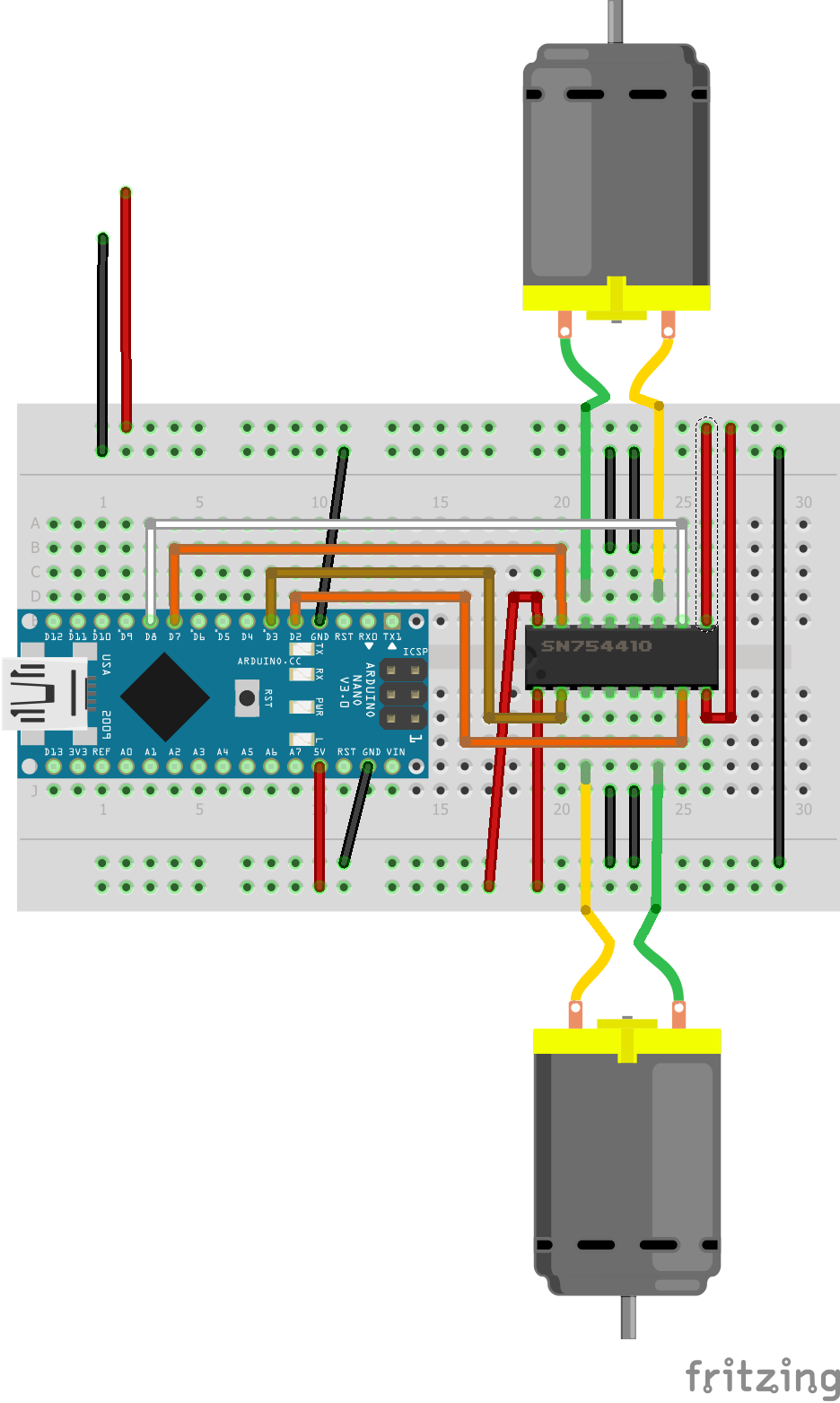
First thing to note is that if you want motors to go forwards and backwards, you need something like an H-Bridge controller. You want to know how an H-Bridge controller works? I am not going to tell you here. I have a very tenous grasp on the secret inner workings of the H-Bridge, so I am not qualified to give a lecture. BUT I will give you a diagram of how to wire one so it works...
The motors I am using are encoded Roomba motors, but I am not using any encoding here. Just the black and red leads are hooked up.
I choose to use the SN74410 chip rather than build out an h-bridge with resistors and crap. It can be done and there are lots of tutorials out there. Nice clean simple chips suit me fine.
The tutorial *Dual Motor Driver* was instrumental in this project. It is specific to the SN74420 chip (interchangable with the L293D h-bridge chip). The code I used came from that guy too.
Diagram:
You might have seen the MPU-6050 from my last project in the video. It is just hanging out, not doing anything... YET.
The black and red power leads are going to a 5V UBEC run off a 3s battery.![]()
*My fritzing diagrams do not show the best routing pathways. They are intended only to show the proper connections.*
Code:
// Use this code to test your motor with the Arduino board:

// if you need PWM, just use the PWM outputs on the Arduino
// and instead of digitalWrite, you should use the analogWrite command

// —————————————————————————  Motors
int motor_left[] = {4, 3};
int motor_right[] = {7, 8};
int ledPin =  13;    // LED connected to digital pin 13

// ————————————————————————— Setup
void setup() {
Serial.begin(9600);

// Setup motors
int i;
for(i = 0; i < 2; i++){
pinMode(motor_left[i], OUTPUT);
pinMode(motor_right[i], OUTPUT);
pinMode(ledPin, OUTPUT);
}

}

// ————————————————————————— Loop
void loop() {

drive_forward();
delay(1000);
motor_stop();
Serial.println("1");

drive_backward();
delay(1000);
motor_stop();
Serial.println("2");

turn_left();
delay(1000);
motor_stop();
Serial.println("3");

turn_right();
delay(1000);
motor_stop();
Serial.println("4");

motor_stop();
delay(1000);
motor_stop();
Serial.println("5");

digitalWrite(ledPin, HIGH);   // set the LED on
  delay(1000);                  // wait for a second
  digitalWrite(ledPin, LOW);    // set the LED off
  delay(1000);                  // wait for a second

}

// ————————————————————————— Drive

void motor_stop(){
digitalWrite(motor_left[0], LOW);
digitalWrite(motor_left[1], LOW);

digitalWrite(motor_right[0], LOW);
digitalWrite(motor_right[1], LOW);
delay(25);
}

void drive_forward(){
digitalWrite(motor_left[0], HIGH);
digitalWrite(motor_left[1], LOW);

digitalWrite(motor_right[0], HIGH);
digitalWrite(motor_right[1], LOW);
}

void drive_backward(){
digitalWrite(motor_left[0], LOW);
digitalWrite(motor_left[1], HIGH);

digitalWrite(motor_right[0], LOW);
digitalWrite(motor_right[1], HIGH);
}

void turn_left(){
digitalWrite(motor_left[0], LOW);
digitalWrite(motor_left[1], HIGH);

digitalWrite(motor_right[0], HIGH);
digitalWrite(motor_right[1], LOW);
}

void turn_right(){
digitalWrite(motor_left[0], HIGH);
digitalWrite(motor_left[1], LOW);

digitalWrite(motor_right[0], LOW);
digitalWrite(motor_right[1], HIGH);
}
I don't know about the PWM comments in the code. The motors I am using are 'supposed' to have PWM input, but work with the code as is. *shrug* -
Mit Servo
01/26/2017 at 15:26 • 0 commentsAdding a servo to any project makes it instantly cool. It's when code reaches out and touches the real world. Building on my last project, the MPU-6050, I have conneted to a servo and a change in attitude results in a change in servo position.
I noticed some jitter, haven't yet figured out how to quell it yet. I tried using a capacitor across the servo power to no avail. Will look into other options and post results here.
![]() The positive and negative wires with no connection are actually connected to an external power source (5V). When activated connected to the 5V pin, the servo killed the Arduino, probably because of excessive current draw on servo start. I am using an 3S battery running a 5V UBEC. Should be sufficient to run a number of servos.
The positive and negative wires with no connection are actually connected to an external power source (5V). When activated connected to the 5V pin, the servo killed the Arduino, probably because of excessive current draw on servo start. I am using an 3S battery running a 5V UBEC. Should be sufficient to run a number of servos.#include "Wire.h" #include "I2Cdev.h" #include "MPU6050.h" #include "Servo.h" MPU6050 mpu; int16_t ax, ay, az; int16_t gx, gy, gz; Servo myservo; int val; int prevVal; void setup() { Wire.begin(); Serial.begin(38400); Serial.println("Initialize MPU"); mpu.initialize(); Serial.println(mpu.testConnection() ? "Connected" : "Connection failed"); myservo.attach(9); } void loop() { mpu.getMotion6(&ax, &ay, &az, &gx, &gy, &gz); val = map(ay, -17000, 17000, 0, 179); if (val != prevVal) { myservo.write(val); prevVal = val; } delay(50); } -
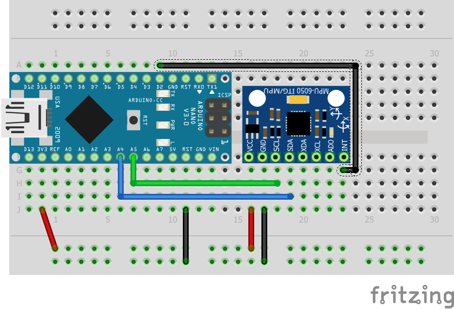
6 degrees of freedom MPU-6050
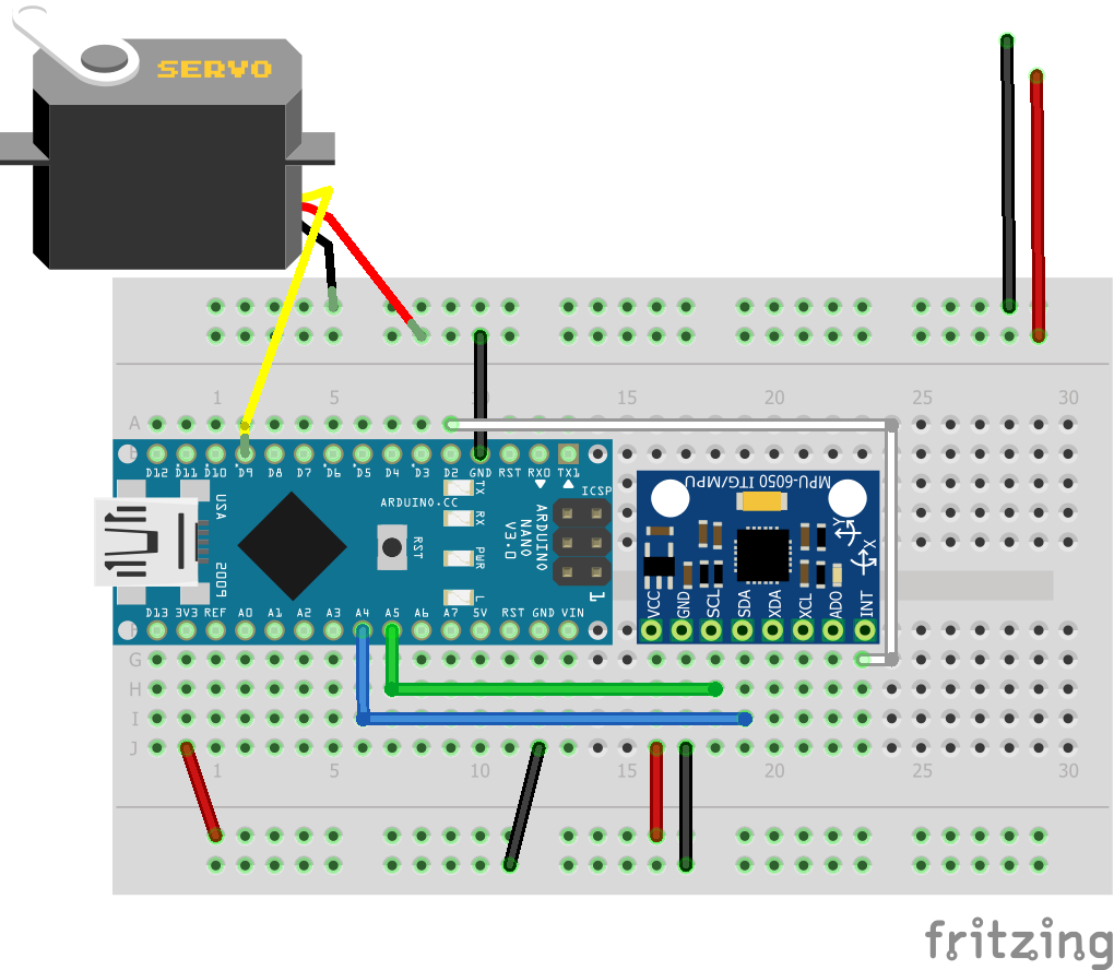
01/25/2017 at 23:23 • 0 commentsThe MPU-6050 is a gyroscope/accelerometer chip. The one I have is on a handy breakout board. It has 8 pins, 5 of which I am going to use. The 3 I will not be using can be used to accept input from another sensor board.
This chip is widely used for balance bots and quad/polycopters. It can also be used for wearable gesture analysis.
I started my journey referring to this tutorial, but not because of it's title. It was the most complete tutorial I could find.
https://diyhacking.com/arduino-mpu-6050-imu-sensor-tutorial/
Part of this tutorial has you install a program called 'Processing 3'. It is a safe program that lets you see serial output in a customizable way. In this instance, using the Teapot sketch, you can see a representation of an airplane follow along with changes in the MPU sensor. Neat.
Follwing the instructions given for the Arduino UNO, I came up with this diagram for hookup to the Nano:
![]()
Please note that I used the 3.3V pin to power the sensor. Some have used 5V, but 3.3V is what the board I have requires.
*This fritzing diagram represents the necessary connections, not necessarily the best routing*
The code by Jeff Rowberg that I used for the Arduino:#include <I2Cdev.h> // I2C device class (I2Cdev) demonstration Arduino sketch for MPU6050 class using DMP (MotionApps v2.0) // 6/21/2012 by Jeff Rowberg <jeff@rowberg.net> // Updates should (hopefully) always be available at https://github.com/jrowberg/i2cdevlib // // Changelog: // 2013-05-08 - added seamless Fastwire support // - added note about gyro calibration // 2012-06-21 - added note about Arduino 1.0.1 + Leonardo compatibility error // 2012-06-20 - improved FIFO overflow handling and simplified read process // 2012-06-19 - completely rearranged DMP initialization code and simplification // 2012-06-13 - pull gyro and accel data from FIFO packet instead of reading directly // 2012-06-09 - fix broken FIFO read sequence and change interrupt detection to RISING // 2012-06-05 - add gravity-compensated initial reference frame acceleration output // - add 3D math helper file to DMP6 example sketch // - add Euler output and Yaw/Pitch/Roll output formats // 2012-06-04 - remove accel offset clearing for better results (thanks Sungon Lee) // 2012-06-01 - fixed gyro sensitivity to be 2000 deg/sec instead of 250 // 2012-05-30 - basic DMP initialization working /* ============================================ I2Cdev device library code is placed under the MIT license Copyright (c) 2012 Jeff Rowberg Permission is hereby granted, free of charge, to any person obtaining a copy of this software and associated documentation files (the "Software"), to deal in the Software without restriction, including without limitation the rights to use, copy, modify, merge, publish, distribute, sublicense, and/or sell copies of the Software, and to permit persons to whom the Software is furnished to do so, subject to the following conditions: The above copyright notice and this permission notice shall be included in all copies or substantial portions of the Software. THE SOFTWARE IS PROVIDED "AS IS", WITHOUT WARRANTY OF ANY KIND, EXPRESS OR IMPLIED, INCLUDING BUT NOT LIMITED TO THE WARRANTIES OF MERCHANTABILITY, FITNESS FOR A PARTICULAR PURPOSE AND NONINFRINGEMENT. IN NO EVENT SHALL THE AUTHORS OR COPYRIGHT HOLDERS BE LIABLE FOR ANY CLAIM, DAMAGES OR OTHER LIABILITY, WHETHER IN AN ACTION OF CONTRACT, TORT OR OTHERWISE, ARISING FROM, OUT OF OR IN CONNECTION WITH THE SOFTWARE OR THE USE OR OTHER DEALINGS IN THE SOFTWARE. =============================================== */ // I2Cdev and MPU6050 must be installed as libraries, or else the .cpp/.h files // for both classes must be in the include path of your project #include "I2Cdev.h" #include "MPU6050_6Axis_MotionApps20.h" //#include "MPU6050.h" // not necessary if using MotionApps include file // Arduino Wire library is required if I2Cdev I2CDEV_ARDUINO_WIRE implementation // is used in I2Cdev.h #if I2CDEV_IMPLEMENTATION == I2CDEV_ARDUINO_WIRE #include "Wire.h" #endif // class default I2C address is 0x68 // specific I2C addresses may be passed as a parameter here // AD0 low = 0x68 (default for SparkFun breakout and InvenSense evaluation board) // AD0 high = 0x69 MPU6050 mpu; //MPU6050 mpu(0x69); // <-- use for AD0 high /* ========================================================================= NOTE: In addition to connection 3.3v, GND, SDA, and SCL, this sketch depends on the MPU-6050's INT pin being connected to the Arduino's external interrupt #0 pin. On the Arduino Uno and Mega 2560, this is digital I/O pin 2. * ========================================================================= */ /* ========================================================================= NOTE: Arduino v1.0.1 with the Leonardo board generates a compile error when using Serial.write(buf, len). The Teapot output uses this method. The solution requires a modification to the Arduino USBAPI.h file, which is fortunately simple, but annoying. This will be fixed in the next IDE release. For more info, see these links: http://arduino.cc/forum/index.php/topic,109987.0.html http://code.google.com/p/arduino/issues/detail?id=958 * ========================================================================= */ // uncomment "OUTPUT_READABLE_QUATERNION" if you want to see the actual // quaternion components in a [w, x, y, z] format (not best for parsing // on a remote host such as Processing or something though) //#define OUTPUT_READABLE_QUATERNION // uncomment "OUTPUT_READABLE_EULER" if you want to see Euler angles // (in degrees) calculated from the quaternions coming from the FIFO. // Note that Euler angles suffer from gimbal lock (for more info, see // http://en.wikipedia.org/wiki/Gimbal_lock) //#define OUTPUT_READABLE_EULER // uncomment "OUTPUT_READABLE_YAWPITCHROLL" if you want to see the yaw/ // pitch/roll angles (in degrees) calculated from the quaternions coming // from the FIFO. Note this also requires gravity vector calculations. // Also note that yaw/pitch/roll angles suffer from gimbal lock (for // more info, see: http://en.wikipedia.org/wiki/Gimbal_lock) //#define OUTPUT_READABLE_YAWPITCHROLL // uncomment "OUTPUT_READABLE_REALACCEL" if you want to see acceleration // components with gravity removed. This acceleration reference frame is // not compensated for orientation, so +X is always +X according to the // sensor, just without the effects of gravity. If you want acceleration // compensated for orientation, us OUTPUT_READABLE_WORLDACCEL instead. //#define OUTPUT_READABLE_REALACCEL // uncomment "OUTPUT_READABLE_WORLDACCEL" if you want to see acceleration // components with gravity removed and adjusted for the world frame of // reference (yaw is relative to initial orientation, since no magnetometer // is present in this case). Could be quite handy in some cases. //#define OUTPUT_READABLE_WORLDACCEL // uncomment "OUTPUT_TEAPOT" if you want output that matches the // format used for the InvenSense teapot demo #define OUTPUT_TEAPOT #define LED_PIN 13 // (Arduino is 13, Teensy is 11, Teensy++ is 6) bool blinkState = false; // MPU control/status vars bool dmpReady = false; // set true if DMP init was successful uint8_t mpuIntStatus; // holds actual interrupt status byte from MPU uint8_t devStatus; // return status after each device operation (0 = success, !0 = error) uint16_t packetSize; // expected DMP packet size (default is 42 bytes) uint16_t fifoCount; // count of all bytes currently in FIFO uint8_t fifoBuffer[64]; // FIFO storage buffer // orientation/motion vars Quaternion q; // [w, x, y, z] quaternion container VectorInt16 aa; // [x, y, z] accel sensor measurements VectorInt16 aaReal; // [x, y, z] gravity-free accel sensor measurements VectorInt16 aaWorld; // [x, y, z] world-frame accel sensor measurements VectorFloat gravity; // [x, y, z] gravity vector float euler[3]; // [psi, theta, phi] Euler angle container float ypr[3]; // [yaw, pitch, roll] yaw/pitch/roll container and gravity vector // packet structure for InvenSense teapot demo uint8_t teapotPacket[14] = { '$', 0x02, 0,0, 0,0, 0,0, 0,0, 0x00, 0x00, '\r', '\n' }; // ================================================================ // === INTERRUPT DETECTION ROUTINE === // ================================================================ volatile bool mpuInterrupt = false; // indicates whether MPU interrupt pin has gone high void dmpDataReady() { mpuInterrupt = true; } // ================================================================ // === INITIAL SETUP === // ================================================================ void setup() { // join I2C bus (I2Cdev library doesn't do this automatically) #if I2CDEV_IMPLEMENTATION == I2CDEV_ARDUINO_WIRE Wire.begin(); TWBR = 24; // 400kHz I2C clock (200kHz if CPU is 8MHz) #elif I2CDEV_IMPLEMENTATION == I2CDEV_BUILTIN_FASTWIRE Fastwire::setup(400, true); #endif // initialize serial communication // (115200 chosen because it is required for Teapot Demo output, but it's // really up to you depending on your project) Serial.begin(115200); while (!Serial); // wait for Leonardo enumeration, others continue immediately // NOTE: 8MHz or slower host processors, like the Teensy @ 3.3v or Ardunio // Pro Mini running at 3.3v, cannot handle this baud rate reliably due to // the baud timing being too misaligned with processor ticks. You must use // 38400 or slower in these cases, or use some kind of external separate // crystal solution for the UART timer. // initialize device Serial.println(F("Initializing I2C devices...")); mpu.initialize(); // verify connection Serial.println(F("Testing device connections...")); Serial.println(mpu.testConnection() ? F("MPU6050 connection successful") : F("MPU6050 connection failed")); // wait for ready Serial.println(F("\nSend any character to begin DMP programming and demo: ")); while (Serial.available() && Serial.read()); // empty buffer while (!Serial.available()); // wait for data while (Serial.available() && Serial.read()); // empty buffer again // load and configure the DMP Serial.println(F("Initializing DMP...")); devStatus = mpu.dmpInitialize(); // supply your own gyro offsets here, scaled for min sensitivity mpu.setXGyroOffset(220); mpu.setYGyroOffset(76); mpu.setZGyroOffset(-85); mpu.setZAccelOffset(1788); // 1688 factory default for my test chip // make sure it worked (returns 0 if so) if (devStatus == 0) { // turn on the DMP, now that it's ready Serial.println(F("Enabling DMP...")); mpu.setDMPEnabled(true); // enable Arduino interrupt detection Serial.println(F("Enabling interrupt detection (Arduino external interrupt 0)...")); attachInterrupt(0, dmpDataReady, RISING); mpuIntStatus = mpu.getIntStatus(); // set our DMP Ready flag so the main loop() function knows it's okay to use it Serial.println(F("DMP ready! Waiting for first interrupt...")); dmpReady = true; // get expected DMP packet size for later comparison packetSize = mpu.dmpGetFIFOPacketSize(); } else { // ERROR! // 1 = initial memory load failed // 2 = DMP configuration updates failed // (if it's going to break, usually the code will be 1) Serial.print(F("DMP Initialization failed (code ")); Serial.print(devStatus); Serial.println(F(")")); } // configure LED for output pinMode(LED_PIN, OUTPUT); } // ================================================================ // === MAIN PROGRAM LOOP === // ================================================================ void loop() { // if programming failed, don't try to do anything if (!dmpReady) return; // wait for MPU interrupt or extra packet(s) available while (!mpuInterrupt && fifoCount < packetSize) { // other program behavior stuff here // . // . // . // if you are really paranoid you can frequently test in between other // stuff to see if mpuInterrupt is true, and if so, "break;" from the // while() loop to immediately process the MPU data // . // . // . } // reset interrupt flag and get INT_STATUS byte mpuInterrupt = false; mpuIntStatus = mpu.getIntStatus(); // get current FIFO count fifoCount = mpu.getFIFOCount(); // check for overflow (this should never happen unless our code is too inefficient) if ((mpuIntStatus & 0x10) || fifoCount == 1024) { // reset so we can continue cleanly mpu.resetFIFO(); Serial.println(F("FIFO overflow!")); // otherwise, check for DMP data ready interrupt (this should happen frequently) } else if (mpuIntStatus & 0x02) { // wait for correct available data length, should be a VERY short wait while (fifoCount < packetSize) fifoCount = mpu.getFIFOCount(); // read a packet from FIFO mpu.getFIFOBytes(fifoBuffer, packetSize); // track FIFO count here in case there is > 1 packet available // (this lets us immediately read more without waiting for an interrupt) fifoCount -= packetSize; #ifdef OUTPUT_READABLE_QUATERNION // display quaternion values in easy matrix form: w x y z mpu.dmpGetQuaternion(&q, fifoBuffer); Serial.print("quat\t"); Serial.print(q.w); Serial.print("\t"); Serial.print(q.x); Serial.print("\t"); Serial.print(q.y); Serial.print("\t"); Serial.println(q.z); #endif #ifdef OUTPUT_READABLE_EULER // display Euler angles in degrees mpu.dmpGetQuaternion(&q, fifoBuffer); mpu.dmpGetEuler(euler, &q); Serial.print("euler\t"); Serial.print(euler[0] * 180/M_PI); Serial.print("\t"); Serial.print(euler[1] * 180/M_PI); Serial.print("\t"); Serial.println(euler[2] * 180/M_PI); #endif #ifdef OUTPUT_READABLE_YAWPITCHROLL // display Euler angles in degrees mpu.dmpGetQuaternion(&q, fifoBuffer); mpu.dmpGetGravity(&gravity, &q); mpu.dmpGetYawPitchRoll(ypr, &q, &gravity); Serial.print("ypr\t"); Serial.print(ypr[0] * 180/M_PI); Serial.print("\t"); Serial.print(ypr[1] * 180/M_PI); Serial.print("\t"); Serial.println(ypr[2] * 180/M_PI); #endif #ifdef OUTPUT_READABLE_REALACCEL // display real acceleration, adjusted to remove gravity mpu.dmpGetQuaternion(&q, fifoBuffer); mpu.dmpGetAccel(&aa, fifoBuffer); mpu.dmpGetGravity(&gravity, &q); mpu.dmpGetLinearAccel(&aaReal, &aa, &gravity); Serial.print("areal\t"); Serial.print(aaReal.x); Serial.print("\t"); Serial.print(aaReal.y); Serial.print("\t"); Serial.println(aaReal.z); #endif #ifdef OUTPUT_READABLE_WORLDACCEL // display initial world-frame acceleration, adjusted to remove gravity // and rotated based on known orientation from quaternion mpu.dmpGetQuaternion(&q, fifoBuffer); mpu.dmpGetAccel(&aa, fifoBuffer); mpu.dmpGetGravity(&gravity, &q); mpu.dmpGetLinearAccel(&aaReal, &aa, &gravity); mpu.dmpGetLinearAccelInWorld(&aaWorld, &aaReal, &q); Serial.print("aworld\t"); Serial.print(aaWorld.x); Serial.print("\t"); Serial.print(aaWorld.y); Serial.print("\t"); Serial.println(aaWorld.z); #endif #ifdef OUTPUT_TEAPOT // display quaternion values in InvenSense Teapot demo format: teapotPacket[2] = fifoBuffer[0]; teapotPacket[3] = fifoBuffer[1]; teapotPacket[4] = fifoBuffer[4]; teapotPacket[5] = fifoBuffer[5]; teapotPacket[6] = fifoBuffer[8]; teapotPacket[7] = fifoBuffer[9]; teapotPacket[8] = fifoBuffer[12]; teapotPacket[9] = fifoBuffer[13]; Serial.write(teapotPacket, 14); teapotPacket[11]++; // packetCount, loops at 0xFF on purpose #endif // blink LED to indicate activity blinkState = !blinkState; digitalWrite(LED_PIN, blinkState); } }I know it seems like a lot, but thats why cut&paste was invented, am I right?
Now to try to figure out how to run servos based on this board for auto levelling...
-
Rangefinding
01/25/2017 at 17:49 • 0 commentsI am gong to redirect here to my stand-alone project 'DumDum Detector' because I have already put work into writing up that project.
http://bit.ly/dumdumdetector