Tron9000
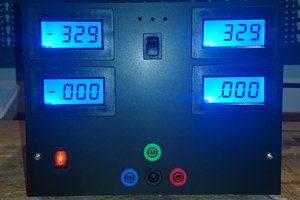
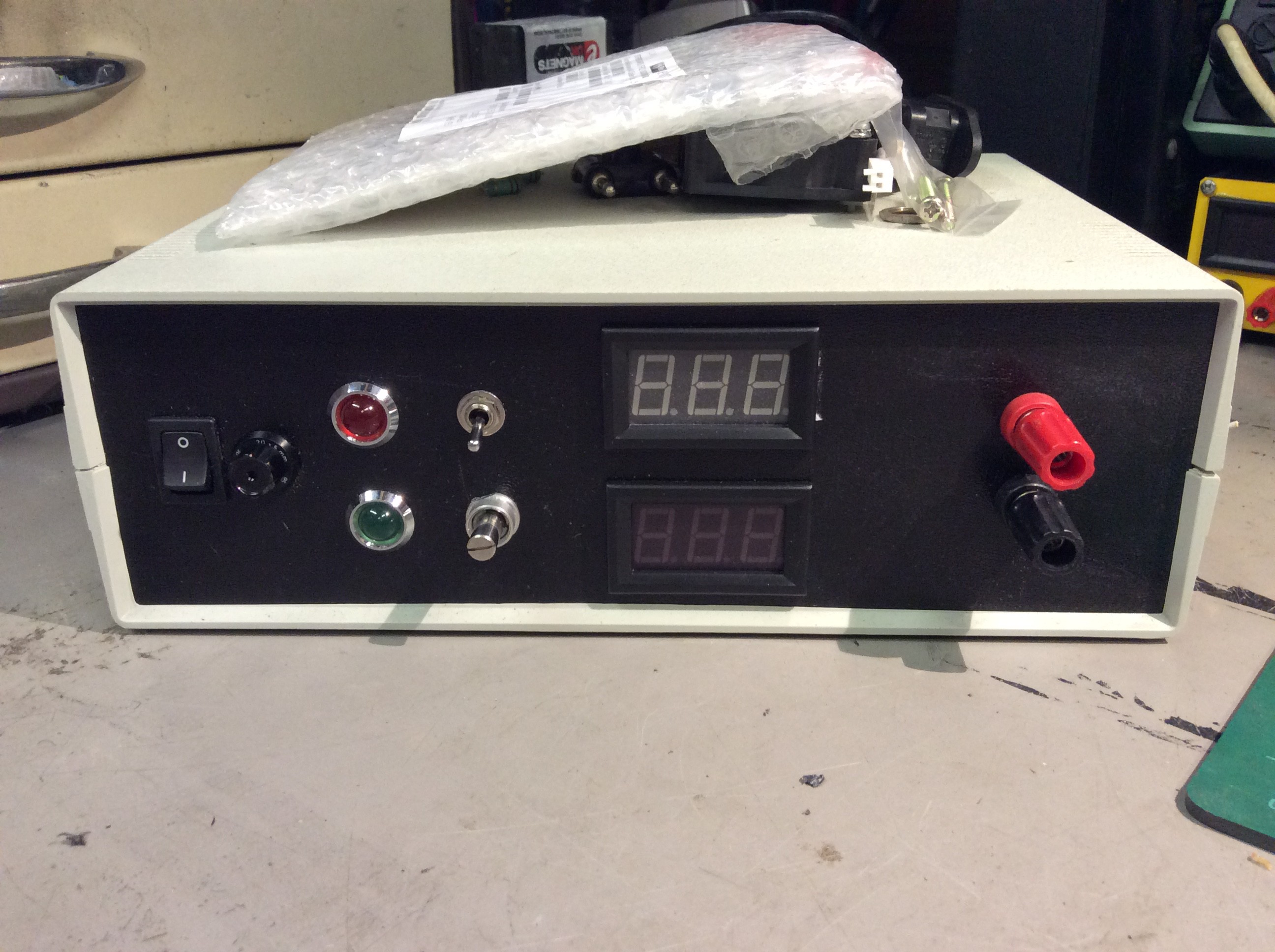
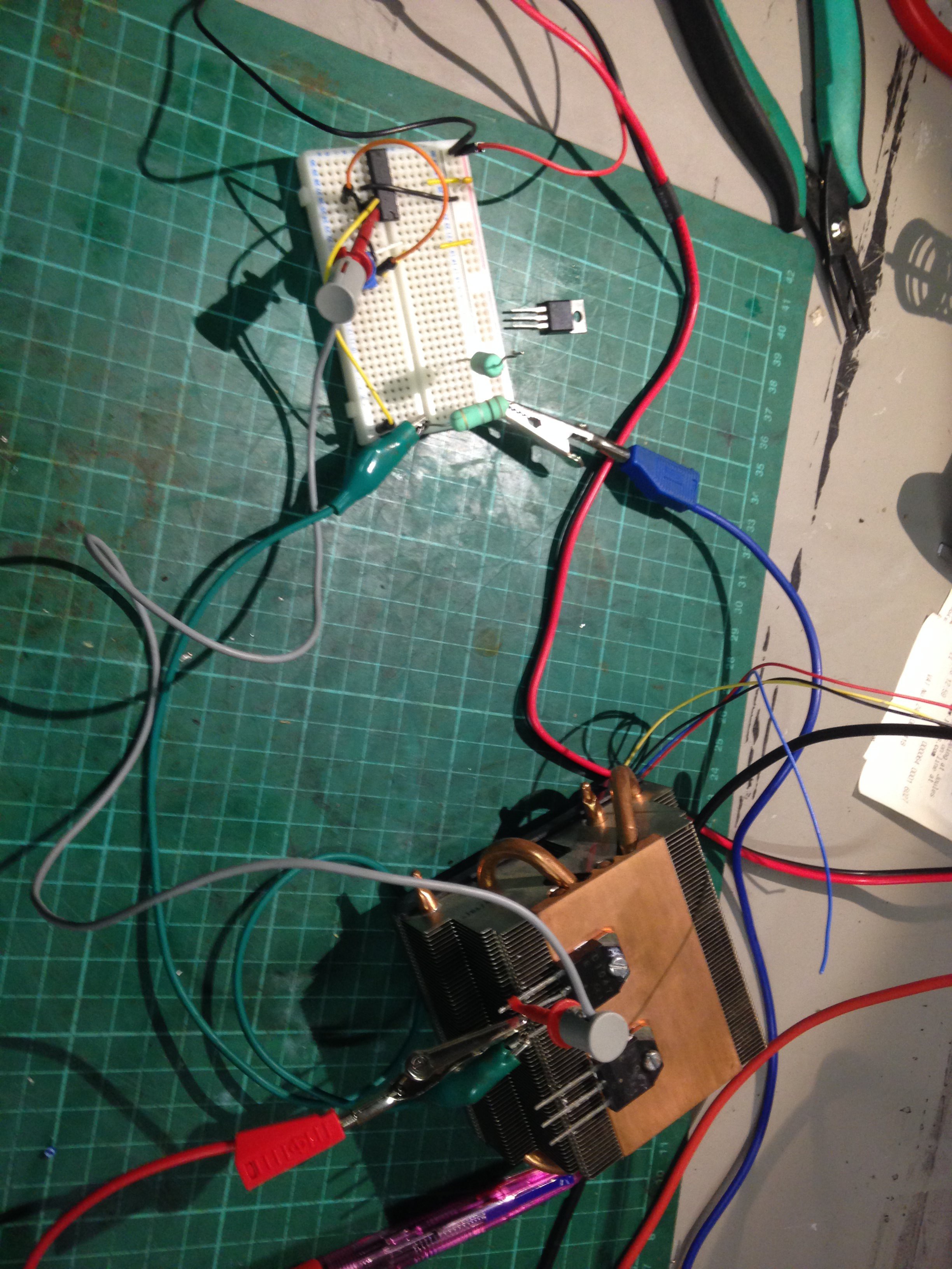
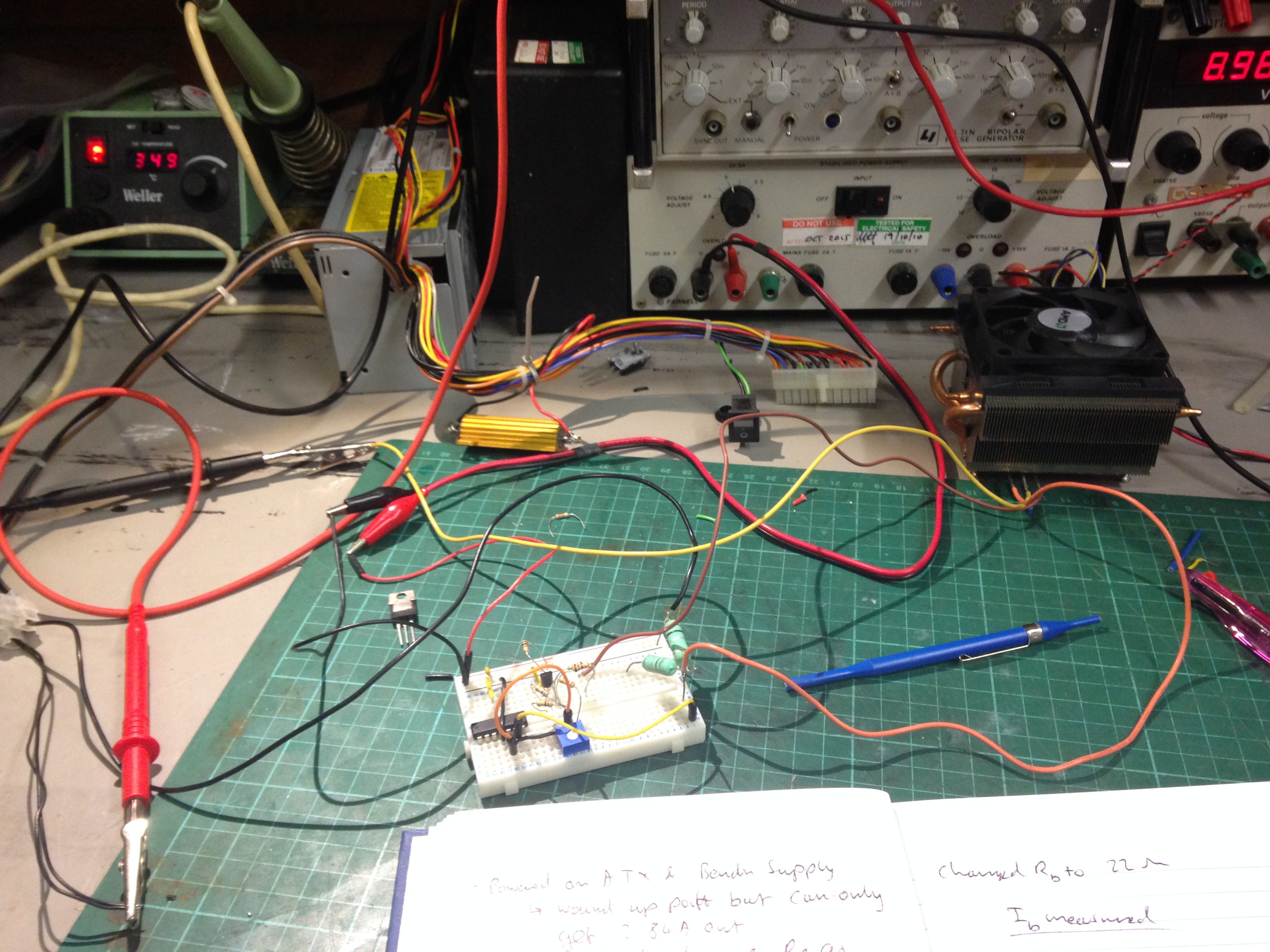
As mentioned the aim is to build a active load out of salvaged parts and the like. But this has also got a purpose to serve. I have some 18650 cells that need testing and in order to know what capacity they are I'm going to charge them up and load test them to verify their capacity.
This is also a learning experience. I believe that the only way for things to stick in any engineering discipline is to design, test, fail, fix, build, test, fail, fix, finish and fix for the rest of your life!
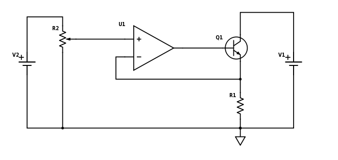
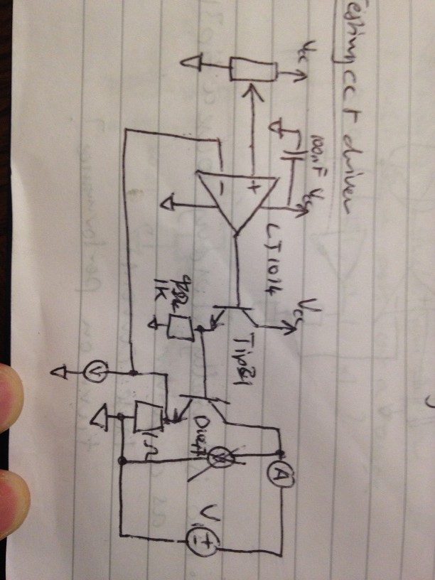
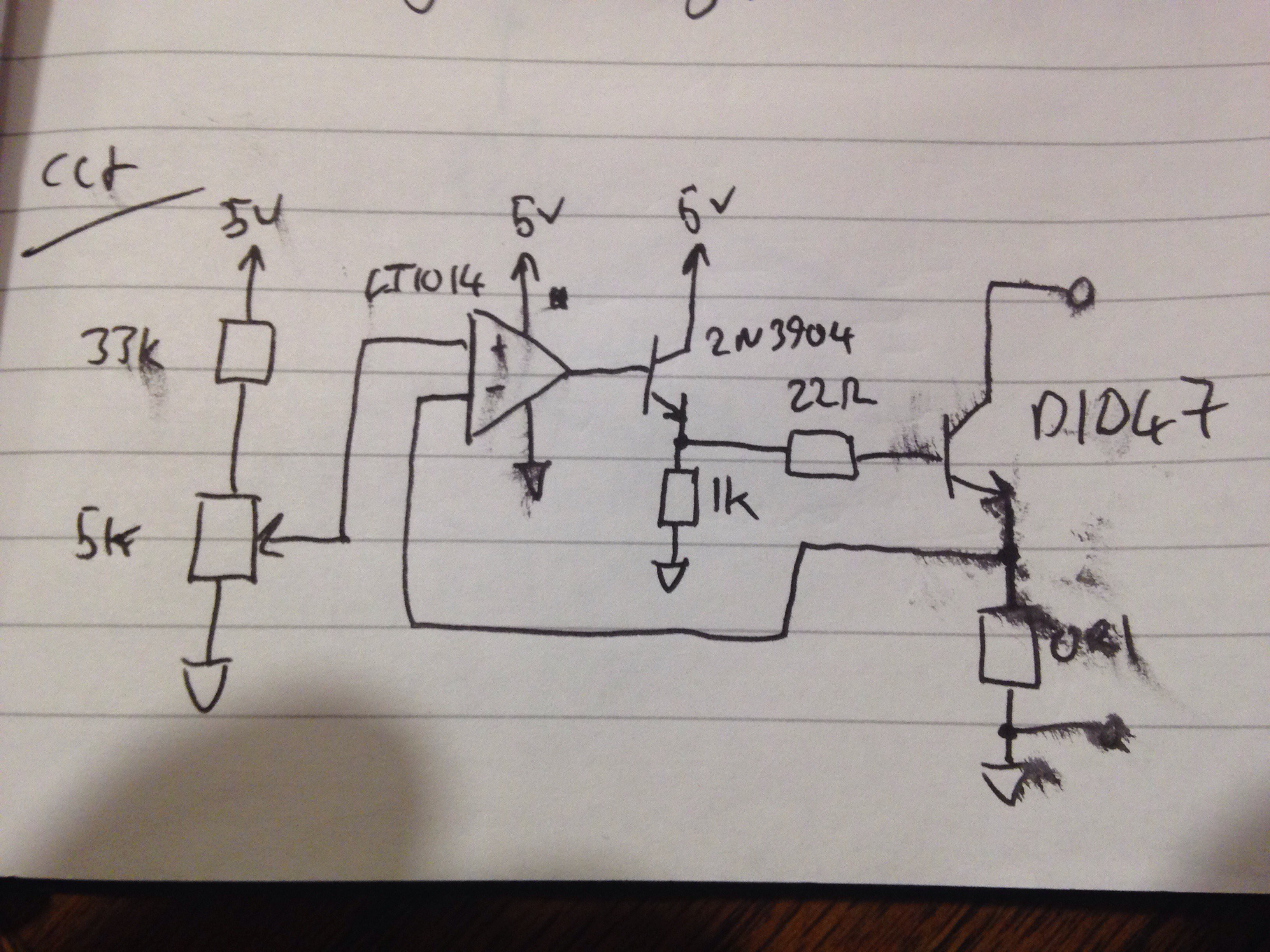
Basically I've known the modus-operandi of this circuit since first looking at it and have always wanted to build one and now I have collected enough parts to do it, its time to knuckle down!
Some Specifications - here's is what I know I want, these will be subject to change depending on resources.
Electrical/Instrument specifications
| Criteria | Max | Typ. | Min. |
| Load Instrumentation | |||
| input load voltage (V DC) | 32 | 30 | |
| Load Max Current (A) - depending on resources | 5A | 3A | |
| Load Max Power (W) - depending on resources | 120 | 60 | |
| Current resolution (A)- depending on resources | 0.001 | 0.01 | |
| Current Accuracy - depending on resources | 1% | 2.5% | 5% |
| Display resolution | 4-digit | 3-digit | |
| Display Accuracy | 1% | 5% | |
| Load Current overshoot | 5% | ||
| Load current Settling time (ms) | 1 | ||
| Load current rise time (ms) | 0.5 | ||
| Power supply | |||
| Circuitry Supply voltage (V DC) | 15 | 12 | |
| Supply Input Voltage (V AC) | 240 | 110 | |
| Main supply Power(W) | 10 | ||
| Electronics supply current (A) | 2 | 0.5 | |
| Safety | |||
| Safety Class | 2 | ||
| Mains side input fuse | Fitted |
Features
| Criteria | Must Have | Will have | Nice to Have | Resource dependant |
| Power on indicator | Y | |||
| Load active indicator | Y | |||
| Mains input protection | Y | |||
| load input OV indication/protection | Y | Y | ||
| Max load power indication/protection | Y | Y | ||
| Front panel mains switch | Y | |||
| Voltage/Current display | Y | |||
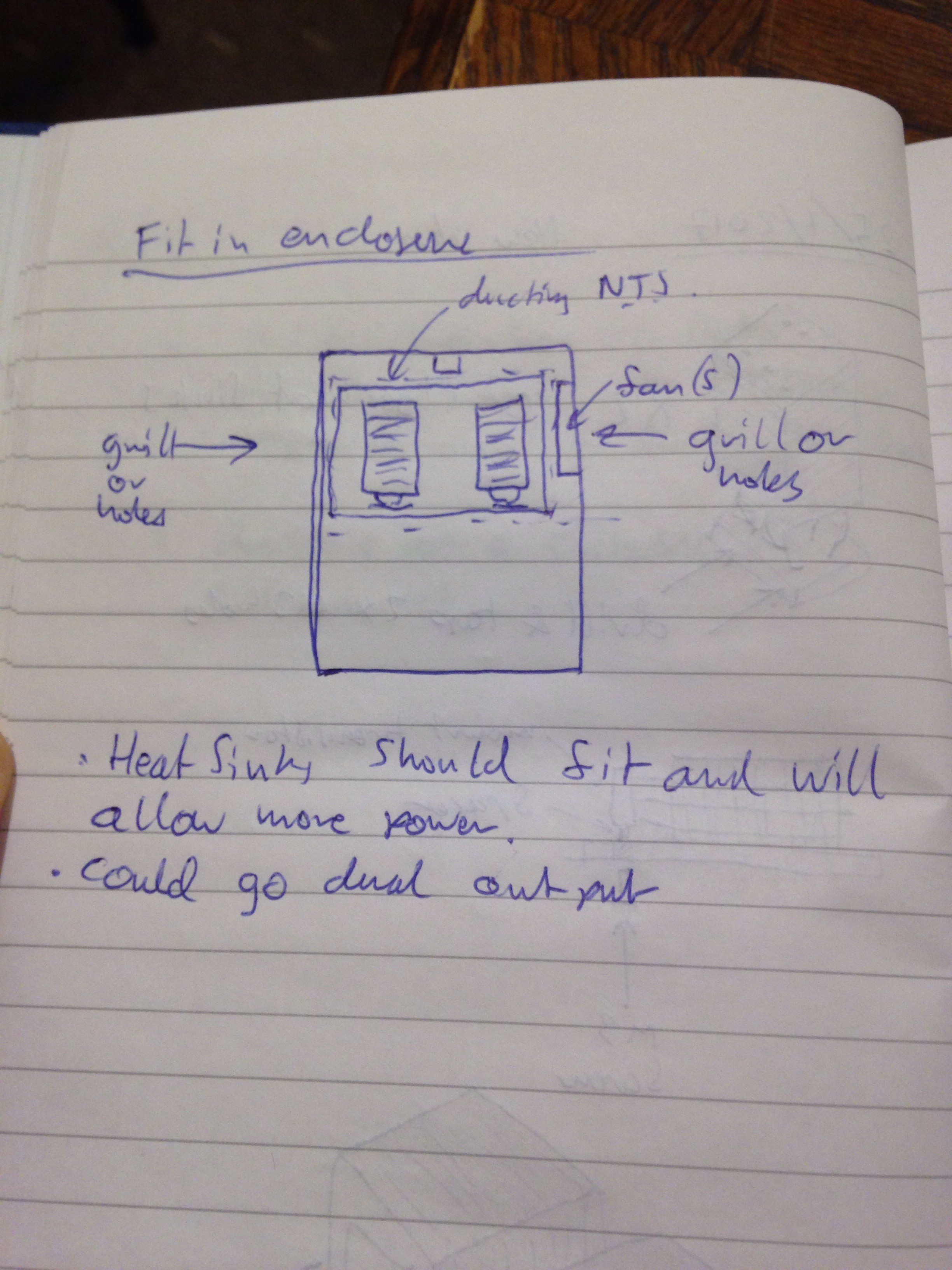
| Dual Channel Capability | Y | Y | ||
| multi-turn adjustment pot | Y | |||
| Load output on/off switch | Y | |||
| Complete Load Isolation when load off | Y | |||
| IEC inlet for ease of portability and installation | Y | |||
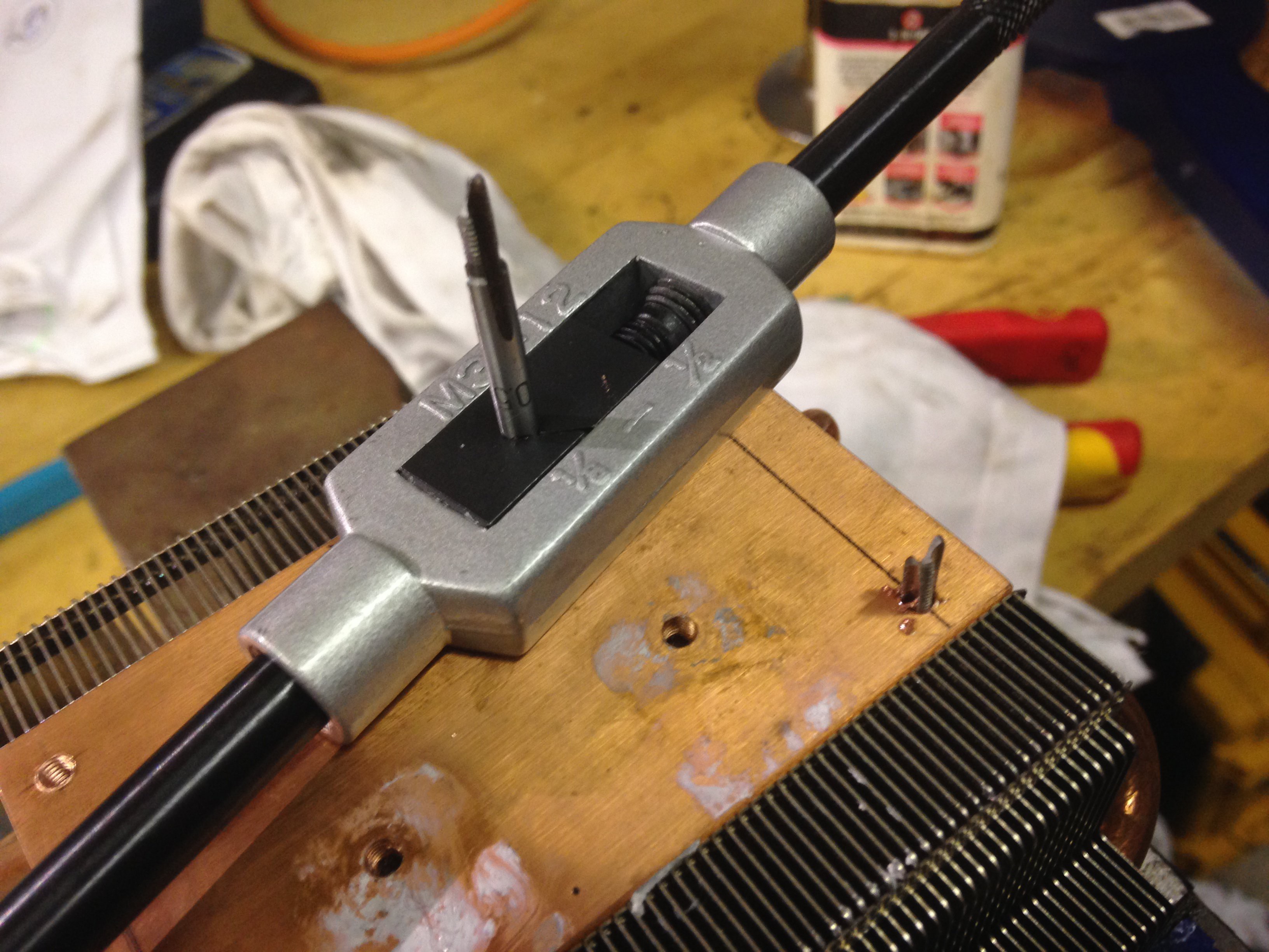
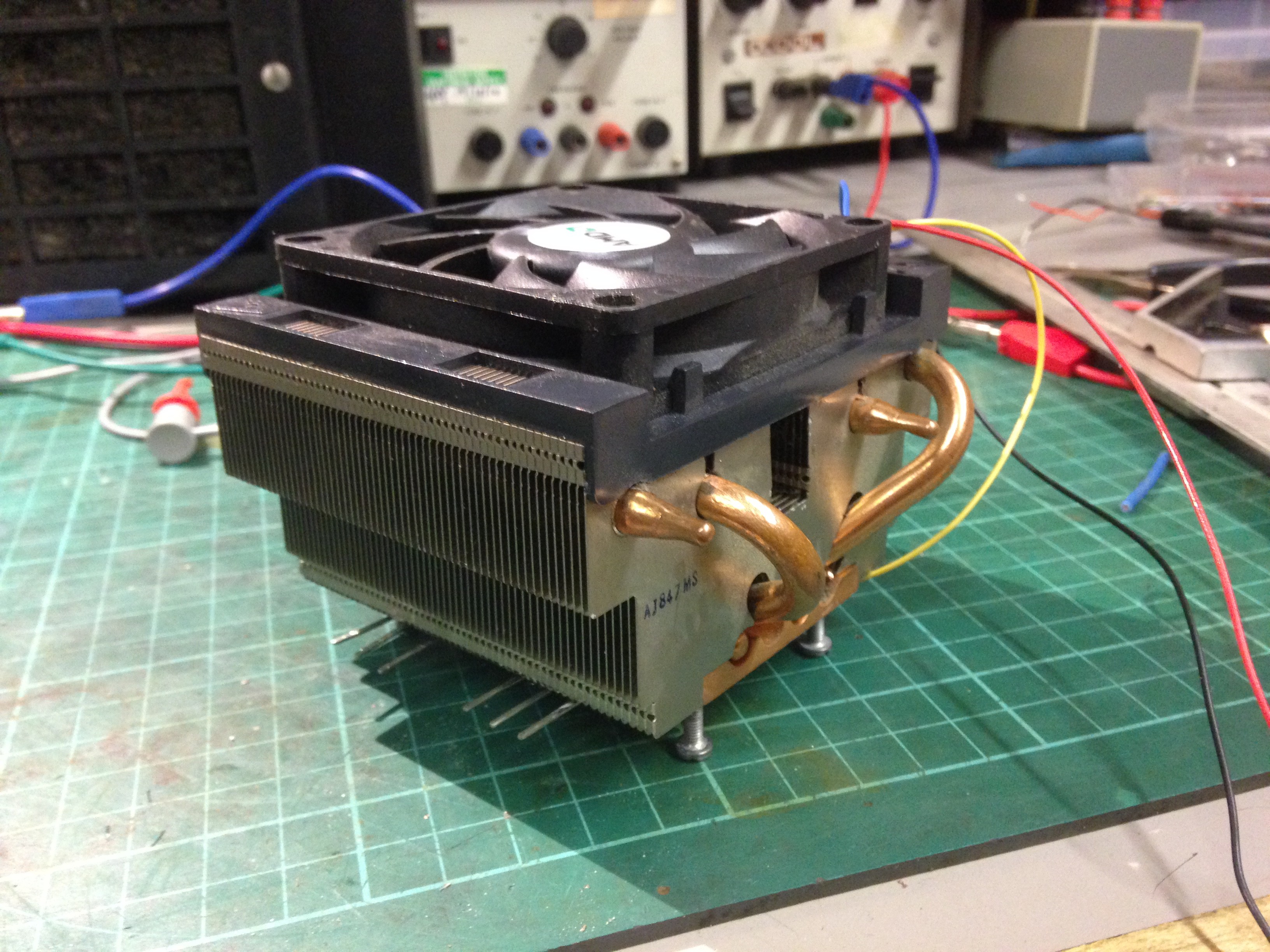
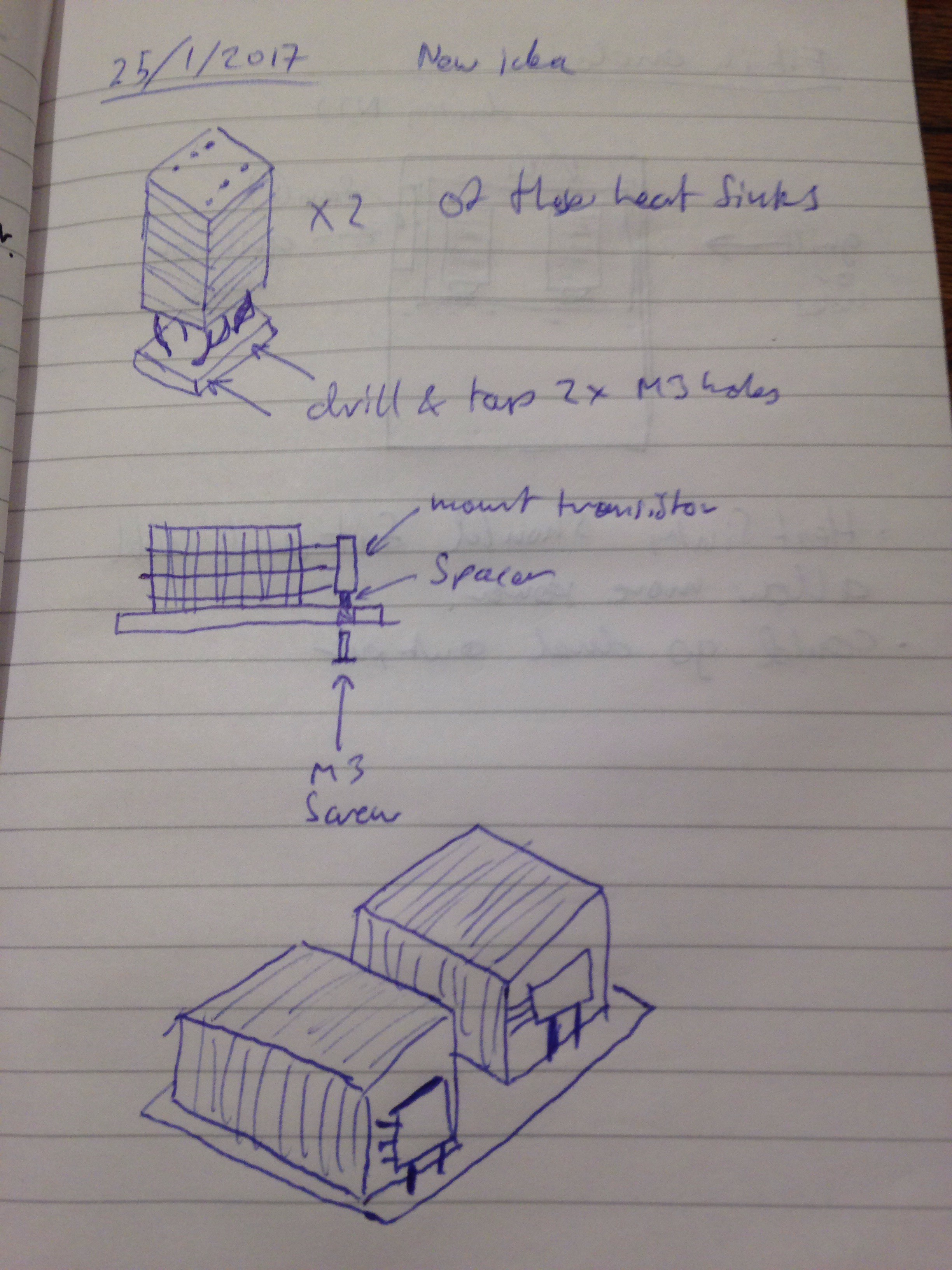
| Active cooling for Load | Y | |||
| Temperature controlled active cooling | Y | Y | ||
| standard 3/4" spacing of 4mm binding posts | Y | |||
| USB Load port | Y | |||
| External control signal input | Y | Y | ||
| Capacity Reading/Display | Y | |||
| Silent active cooling | Y |
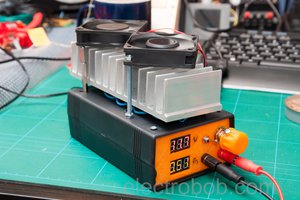
 electrobob
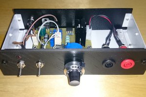
 SUF
SUF
 Jakob Wulfkind